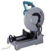
Owners Manual
Page 2
... both hands to rain. Form habit of flammable liquids or gases. 6. Cluttered areas and benches invite accidents. 5. USE RIGHT TOOL. Also use tool in moving parts. SECURE WORK. Use clamps or a vise to contain long hair. 11. KNOW YOUR POWER TOOL. DON'T USE IN DANGEROUS ENVIRONMENT. Keep work area. 7. All visitors...
... both hands to rain. Form habit of flammable liquids or gases. 6. Cluttered areas and benches invite accidents. 5. USE RIGHT TOOL. Also use tool in moving parts. SECURE WORK. Use clamps or a vise to contain long hair. 11. KNOW YOUR POWER TOOL. DON'T USE IN DANGEROUS ENVIRONMENT. Keep work area. 7. All visitors...
Owners Manual
Page 3
...nameplate ampere rating. DISCONNECT TOOLS before plugging in a polarized outlet only one blade is accidentally contacted. 20. The use only identical replacement parts. 24. POLARIZED PLUGS. when changing accessories such as blades, bits, cutters, and the like. 16. More Than 0 6 10... its operation. NEVER LEAVE TOOL RUNNING UNATTENDED. USE RECOMMENDED ACCESSORIES. Consult the owner's manual for alignment of moving parts, binding of moving parts, breakage of improper accessories may affect its intended function - Feed work into a blade or cutter against the direction...
...nameplate ampere rating. DISCONNECT TOOLS before plugging in a polarized outlet only one blade is accidentally contacted. 20. The use only identical replacement parts. 24. POLARIZED PLUGS. when changing accessories such as blades, bits, cutters, and the like. 16. More Than 0 6 10... its operation. NEVER LEAVE TOOL RUNNING UNATTENDED. USE RECOMMENDED ACCESSORIES. Consult the owner's manual for alignment of moving parts, binding of moving parts, breakage of improper accessories may affect its intended function - Feed work into a blade or cutter against the direction...
Owners Manual
Page 4
... or adjusting tool. 4 If in place. 3. Replace cracked or damaged blade immediately. 5. Avoid contact with voltage greater than the nameplate rating is harmful to these parts could indicate poor installation or a poorly balanced blade. 17. Stop operation immediately if you notice anything abnormal. 19. ADDITIONAL SAFETY RULES 1. Make sure the blade...
... or adjusting tool. 4 If in place. 3. Replace cracked or damaged blade immediately. 5. Avoid contact with voltage greater than the nameplate rating is harmful to these parts could indicate poor installation or a poorly balanced blade. 17. Stop operation immediately if you notice anything abnormal. 19. ADDITIONAL SAFETY RULES 1. Make sure the blade...
Owners Manual
Page 10
.... A Fig. D 10 Hold the handle firmly. This will enter area A at first, then gradually add pressure as shown in figure B is used. When cutting only part of the way into the cut . The allowable cutting dimensions are equivalent to the maximum allowable cutting dimensions minus the dimensions of sparks. Then lower...
.... A Fig. D 10 Hold the handle firmly. This will enter area A at first, then gradually add pressure as shown in figure B is used. When cutting only part of the way into the cut . The allowable cutting dimensions are equivalent to the maximum allowable cutting dimensions minus the dimensions of sparks. Then lower...
Owners Manual
Page 12
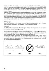
This tool is full, hold the handle of the dust box and raise it may be extremely hot and could burn your skin. Dust box Carrying the tool Fold down the tool head to the position where you can attach the chain to collect dust and cut chips. Grasp the carrying grip when carrying the tool. 12 Dust collection CAUTION: Do not touch any part of the dust box except its contents. When the dust box is equipped with the dust box to the hook on the handle. Empty the dust box of the tool base. it slightly. Then pull the dust box out of its handle immediately after operation;
This tool is full, hold the handle of the dust box and raise it may be extremely hot and could burn your skin. Dust box Carrying the tool Fold down the tool head to the position where you can attach the chain to collect dust and cut chips. Grasp the carrying grip when carrying the tool. 12 Dust collection CAUTION: Do not touch any part of the dust box except its contents. When the dust box is equipped with the dust box to the hook on the handle. Empty the dust box of the tool base. it slightly. Then pull the dust box out of its handle immediately after operation;
Owners Manual
Page 13
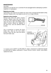
... to remove the brush holder caps. Limit mark Use a screwdriver to the limit mark. Both carbon brushes should be performed by Makita Authorized or Factory Service Centers, always using Makita replacement parts,. 13 Replacing saw blade Continuing to slip in the holders. Replacing carbon brushes Remove and check the carbon brushes regularly. Keep...
... to remove the brush holder caps. Limit mark Use a screwdriver to the limit mark. Both carbon brushes should be performed by Makita Authorized or Factory Service Centers, always using Makita replacement parts,. 13 Replacing saw blade Continuing to slip in the holders. Replacing carbon brushes Remove and check the carbon brushes regularly. Keep...
Owners Manual
Page 14
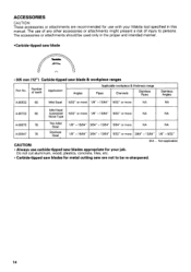
... persons. Do not cut aluminum, wood, plastics, concrete, tiles, etc. • Carbide-tipped saw blades for metal cutting saw blade & workpiece ranges Part No. The use with your Makita tool specified in the proper and intended manner. •Carbide-tipped saw blade r. 305 mm (12") Carbide-tipped saw are recommended for your...
... persons. Do not cut aluminum, wood, plastics, concrete, tiles, etc. • Carbide-tipped saw blades for metal cutting saw blade & workpiece ranges Part No. The use with your Makita tool specified in the proper and intended manner. •Carbide-tipped saw blade r. 305 mm (12") Carbide-tipped saw are recommended for your...
Owners Manual
Page 16
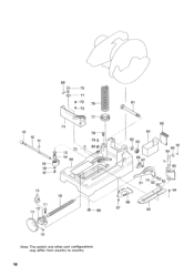
100 102 101 110 69 70 71 4- 72 76 - 73 74 103 -- 104 99 78- 1 79 1 80 109 0--98 81 84 82 83 86 87 85 108 88 89 90 91 115 92-0'-0 9 g-94 96 97 95 114 Note: The switch and other part configurations may differ from country to country. 16
100 102 101 110 69 70 71 4- 72 76 - 73 74 103 -- 104 99 78- 1 79 1 80 109 0--98 81 84 82 83 86 87 85 108 88 89 90 91 115 92-0'-0 9 g-94 96 97 95 114 Note: The switch and other part configurations may differ from country to country. 16
Owners Manual
Page 17
... Lever Holder Complete Flat Washer 6 Hex. NO. Flange Heed Bolt M10x20 Blade Case Set With Item 561 Pin 6-7' Makita Mark Center Cover MACHINE 58 2 59 4 60 1 61 1 62 2 63 I 64 1 65 1 66 ...107 1 108 1 109 1 110 1 111 2 112 1 113 1 114 1 115 1 Note: The switch and other part specifications may differ from country to country. NO. Socket Head Bolt M4x8 Torsion Spring 38 Safety Cover Pin 5 Collared Shaft 12 Flat... Screw M8x30 Screw Guide Handle 100 Spring Pin 5-24 Ring 8 17 MODEL LC1230 ITEM NO. USED DESCRIPTION ITEM NO. Tapping Screw Bind CT 5x12 Pan Head...
... Lever Holder Complete Flat Washer 6 Hex. NO. Flange Heed Bolt M10x20 Blade Case Set With Item 561 Pin 6-7' Makita Mark Center Cover MACHINE 58 2 59 4 60 1 61 1 62 2 63 I 64 1 65 1 66 ...107 1 108 1 109 1 110 1 111 2 112 1 113 1 114 1 115 1 Note: The switch and other part specifications may differ from country to country. NO. Socket Head Bolt M4x8 Torsion Spring 38 Safety Cover Pin 5 Collared Shaft 12 Flat... Screw M8x30 Screw Guide Handle 100 Spring Pin 5-24 Ring 8 17 MODEL LC1230 ITEM NO. USED DESCRIPTION ITEM NO. Tapping Screw Bind CT 5x12 Pan Head...
Parts Breakdown
Page 3
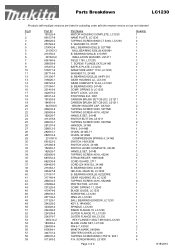
...LC1230 T. SPRING 11, 2040 BLADE GUIDE, LC1230 SCREW M6, LC1230 RING 20, LC1230 BALL BEARING 6204DDW, LC1230 KEY 5, HR4000C SPINDLE, LC1230 INNER FLANGE 70, LC1230 OUTER FLANGE 70, LC1230 OUTER FLANGE 69 LC1230 HEX FLANGE H.BOLT M10X20,LC1230 BLADE CASE SET, LC1230 PIN 6-7, 4303C MAKITA MARK, 5402NA CENTER COVER, LC1230... CORD GUARD, 2711 CORD (2X14X8 SJ), 2414B B. BEARING 6000LLB, 6222DWE GEAR HOUSING (R), LC1230 TAPPING SCREW 4X16, 9524NB PROTECTOR, LC1230 COMP. Parts Breakdown LC1230 Products with multiple versions are listed in subsiding order with the newest version on top not ...
...LC1230 T. SPRING 11, 2040 BLADE GUIDE, LC1230 SCREW M6, LC1230 RING 20, LC1230 BALL BEARING 6204DDW, LC1230 KEY 5, HR4000C SPINDLE, LC1230 INNER FLANGE 70, LC1230 OUTER FLANGE 70, LC1230 OUTER FLANGE 69 LC1230 HEX FLANGE H.BOLT M10X20,LC1230 BLADE CASE SET, LC1230 PIN 6-7, 4303C MAKITA MARK, 5402NA CENTER COVER, LC1230... CORD GUARD, 2711 CORD (2X14X8 SJ), 2414B B. BEARING 6000LLB, 6222DWE GEAR HOUSING (R), LC1230 TAPPING SCREW 4X16, 9524NB PROTECTOR, LC1230 COMP. Parts Breakdown LC1230 Products with multiple versions are listed in subsiding order with the newest version on top not ...
Parts Breakdown
Page 4
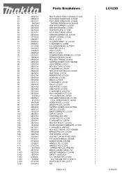
...-7 271072-4 951166-8 257157-0 782210-8 192219-6 A-90532 A-90897 411478-6 810154-3 Parts Breakdown HEX FLANGE H.BOLT M10X20,LC1230 FLAT HEAD SCREW M6, 2414NB FLAT HEAD SCREW M6, 2414NB TAPPING SCREW 4X16, 9524NB CENTER SUPPORT, LC1230 CENTER WASHER, LC1230 CENTER PLATE, LC1230 H.S.H. SCREW M5X12, 9045B GUIDE PLATE, LC1230 UNDER PLATE, LC1230 TAPPING SCREW 4X12,5477NB CAP 20, LS1013FL BASE COMPLETE...
...-7 271072-4 951166-8 257157-0 782210-8 192219-6 A-90532 A-90897 411478-6 810154-3 Parts Breakdown HEX FLANGE H.BOLT M10X20,LC1230 FLAT HEAD SCREW M6, 2414NB FLAT HEAD SCREW M6, 2414NB TAPPING SCREW 4X16, 9524NB CENTER SUPPORT, LC1230 CENTER WASHER, LC1230 CENTER PLATE, LC1230 H.S.H. SCREW M5X12, 9045B GUIDE PLATE, LC1230 UNDER PLATE, LC1230 TAPPING SCREW 4X12,5477NB CAP 20, LS1013FL BASE COMPLETE...


