
Technical Reference
Page 1
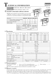
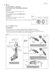
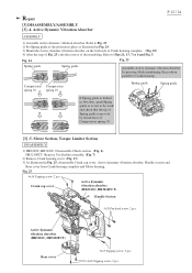
...bulb, Grease vessel (containing 30g of HR3000C, featuring low vibration level and lightweight design. Length (L) Width (W) Height (H) Dimensions: mm (") HR3200C HR3210C HR3210FCT 398 (15-5/8) 424 (16-3/4) 108 (4-1/4) 114 (4-1/2) 239 (9-3/8) Specification Voltage (V) 110 120 220 230 240 Current (A) 8.6 8.2 4.4 4.4 4.4... 50/60 50/60 Continuous Rating (W) Input Output 850 300 --- 300 850 300 850 300 850 300 HR3210FCT Max. HR3200C, HR3210C, HR3210FCT Description Rotary Hammer 32mm (1-1/4") CONCEPT AND MAIN APPLICATIONS PRODUCT P 1/ 24 L H HR3200C series models have been...
...bulb, Grease vessel (containing 30g of HR3000C, featuring low vibration level and lightweight design. Length (L) Width (W) Height (H) Dimensions: mm (") HR3200C HR3210C HR3210FCT 398 (15-5/8) 424 (16-3/4) 108 (4-1/4) 114 (4-1/2) 239 (9-3/8) Specification Voltage (V) 110 120 220 230 240 Current (A) 8.6 8.2 4.4 4.4 4.4... 50/60 50/60 Continuous Rating (W) Input Output 850 300 --- 300 850 300 850 300 850 300 HR3210FCT Max. HR3200C, HR3210C, HR3210FCT Description Rotary Hammer 32mm (1-1/4") CONCEPT AND MAIN APPLICATIONS PRODUCT P 1/ 24 L H HR3200C series models have been...
Technical Reference
Page 3
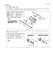
... 57 58 61 Apply a little bit amount of Makita grease R. Item No. Description Portion to lubricate 2 Tool holder cap Lip portion 6 Steel ball 7 Whole portion 10 Steel ball 6 Whole portion Fig. 3 HR3210FCT 2 6 10 HR3200C, HR3210C 2 6 Tool holder Tool holder Repair P 3 / 24 [2] LUBRICATION (Cont.) Regarding HR3210C and HR3210FCT, apply a little bit amount of Makita grease N. Item No.
... 57 58 61 Apply a little bit amount of Makita grease R. Item No. Description Portion to lubricate 2 Tool holder cap Lip portion 6 Steel ball 7 Whole portion 10 Steel ball 6 Whole portion Fig. 3 HR3210FCT 2 6 10 HR3200C, HR3210C 2 6 Tool holder Tool holder Repair P 3 / 24 [2] LUBRICATION (Cont.) Regarding HR3210C and HR3210FCT, apply a little bit amount of Makita grease N. Item No.
Technical Reference
Page 5
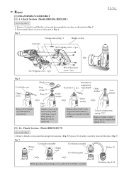
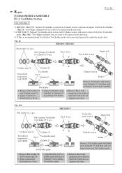
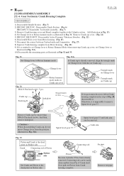
...Steel ball 7: 2 pcs. M5x20 Pan head screw: 2 pcs. with 1R288 Guide washer Remove Steel ball 7 with Slotted screwdriver. Chuck Section (Model HR3210FCT) DISASSEMBLY 1) Remove Handle section and then upright the machine. (Fig. 5) Separate Tool holder assembly from the Machine. (Fig. 7) Fig. 7 ...4x18 Tapping screw: 2 pcs. And then, remove Ring spring 19. Ring 21 can be removed. Chuck Section (Model HR3200, HR3210C) DISASSEMBLY 1) Remove Controller and Handle section and then upright the machine as illustrated in Fig. 5. 2) Disassemble Chuck section as illustrated in Fig. 6....
...Steel ball 7: 2 pcs. M5x20 Pan head screw: 2 pcs. with 1R288 Guide washer Remove Steel ball 7 with Slotted screwdriver. Chuck Section (Model HR3210FCT) DISASSEMBLY 1) Remove Handle section and then upright the machine. (Fig. 5) Separate Tool holder assembly from the Machine. (Fig. 7) Fig. 7 ...4x18 Tapping screw: 2 pcs. And then, remove Ring spring 19. Ring 21 can be removed. Chuck Section (Model HR3200, HR3210C) DISASSEMBLY 1) Remove Controller and Handle section and then upright the machine as illustrated in Fig. 5. 2) Disassemble Chuck section as illustrated in Fig. 6....
Technical Reference
Page 6
... 1. Chuck cover Ring spring 19 Ring 21 Steel ball 7 Guide washer Tool holder Chuck cover can be removed by Compression spring 42. 2. Chuck Section (Model HR3210FCT) DISASSEMBLY 2) The construction of Change ring. 4. And disassemble the front Parts as illustrated in Fig. 11. Fig. 8 Disassemble as illustrated in Figs. 9 and 10. Ring...
... 1. Chuck cover Ring spring 19 Ring 21 Steel ball 7 Guide washer Tool holder Chuck cover can be removed by Compression spring 42. 2. Chuck Section (Model HR3210FCT) DISASSEMBLY 2) The construction of Change ring. 4. And disassemble the front Parts as illustrated in Fig. 11. Fig. 8 Disassemble as illustrated in Figs. 9 and 10. Ring...
Technical Reference
Page 7
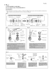
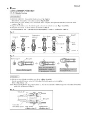
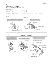
... section as illustrated in Figs. 5 and 6. (Model HR3200C, HR3210C) 1A) Separate Tool holder assembly from Barrel complete as illustrated in Figs 5 and 7. (HR3210FCT) 2) Disassemble Tool holder section (HR3210FCT: Tool holder guide section) together with Cylinder section by striking Tool...Oil seal can be removed from the Machine as illustrated above. Disassemble Crank housing cover and Barrel complete. HR3200C HR3210C Barrel complete Barrel complete Cylinder section Disassemble Tool holder section together with Cylinder section. Refer to Figs. 6 and 5. [3] -1A...
... section as illustrated in Figs. 5 and 6. (Model HR3200C, HR3210C) 1A) Separate Tool holder assembly from Barrel complete as illustrated in Figs 5 and 7. (HR3210FCT) 2) Disassemble Tool holder section (HR3210FCT: Tool holder guide section) together with Cylinder section by striking Tool...Oil seal can be removed from the Machine as illustrated above. Disassemble Crank housing cover and Barrel complete. HR3200C HR3210C Barrel complete Barrel complete Cylinder section Disassemble Tool holder section together with Cylinder section. Refer to Figs. 6 and 5. [3] -1A...
Technical Reference
Page 8
...Holder Section P 8 / 24 DISASSEMBLY 3) HR3200C, HR3210C: Separate Tool holder section from Cylinder section, and remove Impact bolt from Tool holder. (Fig. 14) Now Rings on Impact bolt are ready to be replaced in the next step. 3A) HR3210FCT: Separate Tool holder guide section from Cylinder section, and...be replaced in the next step. 4) If Dust is recognized inside Tool holder (Tool holder guide) after removing Impact bolt, make the inside clean. HR3210FCT Pin 6: 4 pcs. Pin 6 joining Tool holder to Pin 6, 3. And then, pull out Impact bolt from Cylinder 25. Remove Flat washer ...
...Holder Section P 8 / 24 DISASSEMBLY 3) HR3200C, HR3210C: Separate Tool holder section from Cylinder section, and remove Impact bolt from Tool holder. (Fig. 14) Now Rings on Impact bolt are ready to be replaced in the next step. 3A) HR3210FCT: Separate Tool holder guide section from Cylinder section, and...be replaced in the next step. 4) If Dust is recognized inside Tool holder (Tool holder guide) after removing Impact bolt, make the inside clean. HR3210FCT Pin 6: 4 pcs. Pin 6 joining Tool holder to Pin 6, 3. And then, pull out Impact bolt from Cylinder 25. Remove Flat washer ...
Technical Reference
Page 10
... guide) Steel portion of Rubber ring 13 Rubber portion of the disassembling steps. Repair [3] DISASSEMBLY/ASSEMBLY [3] -3. Cylinder Section P 10 / 24 DISASSEMBLY 1) HR3200C, HR3210C: Disassemble Chuck section. (Figs. 5 and 6) HR3210FCT: Disassemble Tool holder assembly. (Figs. 5 and 7) 2) After removing Crank housing cover, disassemble Barrel complete, and separate Tool holder section from Barrel complete. (Fig...
... guide) Steel portion of Rubber ring 13 Rubber portion of the disassembling steps. Repair [3] DISASSEMBLY/ASSEMBLY [3] -3. Cylinder Section P 10 / 24 DISASSEMBLY 1) HR3200C, HR3210C: Disassemble Chuck section. (Figs. 5 and 6) HR3210FCT: Disassemble Tool holder assembly. (Figs. 5 and 7) 2) After removing Crank housing cover, disassemble Barrel complete, and separate Tool holder section from Barrel complete. (Fig...
Technical Reference
Page 11
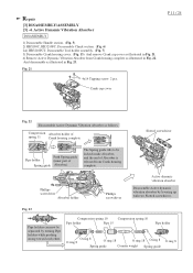
Repair [3] DISASSEMBLY/ASSEMBLY [3] -4. Active Dynamic Vibration Absorber DISASSEMBLY 1) Disassemble Handle section. (Fig. 5) 2) HR3200C, HR3210FC: Disassemble Chuck section. (Fig. 6) 2A) HR3210FCT: Disassemble Tool holder assembly. (Fig. 7) 3) Disassemble Crank housing cover. (Fig. 13) And remove Crank cap cover as illustrated in Fig. 22. Crank cap cover P 11 / ...
Repair [3] DISASSEMBLY/ASSEMBLY [3] -4. Active Dynamic Vibration Absorber DISASSEMBLY 1) Disassemble Handle section. (Fig. 5) 2) HR3200C, HR3210FC: Disassemble Chuck section. (Fig. 6) 2A) HR3210FCT: Disassemble Tool holder assembly. (Fig. 7) 3) Disassemble Crank housing cover. (Fig. 13) And remove Crank cap cover as illustrated in Fig. 22. Crank cap cover P 11 / ...
Technical Reference
Page 12
... 5x25 Tapping screw: 2 pcs. 4x18 Tapping screw: 2 pcs. Motor Section, Torque Limiter Section DISASSEMBLY 1) HR3200C, HR3210C: Disassemble Chuck section. (Fig. 6). Refer to Crank housing. HR3210FCT: Remove Tool holder assembly. (Fig. 7) 2) Remove Crank housing cover. (Fig. 13) 3) As illustrated in Fig...Active Dynamic Vibration Absorber P 12 / 24 ASSEMBLY 1) Assemble Active dynamic vibration absorber. Crank cap cover Active dymamic vibration absorber (HR3210C, HR3210FCT) Handle Section 5x20 Pan head screw: 2 pcs. Refer to Fig. 23. 2) Set Spring guide to the position in ...
... 5x25 Tapping screw: 2 pcs. 4x18 Tapping screw: 2 pcs. Motor Section, Torque Limiter Section DISASSEMBLY 1) HR3200C, HR3210C: Disassemble Chuck section. (Fig. 6). Refer to Crank housing. HR3210FCT: Remove Tool holder assembly. (Fig. 7) 2) Remove Crank housing cover. (Fig. 13) 3) As illustrated in Fig...Active Dynamic Vibration Absorber P 12 / 24 ASSEMBLY 1) Assemble Active dynamic vibration absorber. Crank cap cover Active dymamic vibration absorber (HR3210C, HR3210FCT) Handle Section 5x20 Pan head screw: 2 pcs. Refer to Fig. 23. 2) Set Spring guide to the position in ...
Technical Reference
Page 15
...it is left illustration in Crank Housing Complete P 15 / 24 DISASSEMBLY 1) Disassemble Handle Section (Fig. 5) 2) HR3200C, HR3210C: Disassemble Chuck Section (Fig. 6) HR3210FCT: Disassemble Tool holder assembly. (Fig. 7) 3) Remove Crank housing cover and Barrel complete together with that on Striker side Crank...31. Spiral bevel gear 37 Spiral bevel gear 37 and Link arm can be removed. Remove Crank cap cover. (Fig. 21) 5) HR3210C, HR3210FCT: Disassemble Active Dynamic Vibration Absorber. (Fig. 22) 6) Disassemble Rear cover from Motor housing. (Fig. 25) 7) Disconnect the contact ...
...it is left illustration in Crank Housing Complete P 15 / 24 DISASSEMBLY 1) Disassemble Handle Section (Fig. 5) 2) HR3200C, HR3210C: Disassemble Chuck Section (Fig. 6) HR3210FCT: Disassemble Tool holder assembly. (Fig. 7) 3) Remove Crank housing cover and Barrel complete together with that on Striker side Crank...31. Spiral bevel gear 37 Spiral bevel gear 37 and Link arm can be removed. Remove Crank cap cover. (Fig. 21) 5) HR3210C, HR3210FCT: Disassemble Active Dynamic Vibration Absorber. (Fig. 22) 6) Disassemble Rear cover from Motor housing. (Fig. 25) 7) Disconnect the contact ...
Technical Reference
Page 19
...4x18 Tapping screw : 1 pc. Compression spring 11 Dust cover support Dust cover Lead unit ON-OFF Switch Handle base 5x25 Tapping screw: 2 pcs. HR3210C HR3210FCT Replace ON-OFF Switch etc. Switch holder Switch lever complete 5x40 Tapping Screw: 2 pcs. ON-OFF Switch can be replaced as illustrated in Fig. ...pcs. Flat washer 5: 2 pcs. Replace ON-OFF Switch etc. Handle Section and Electrical Parts DISASSEMBLY 1) Disassemble Handle section as illustrated in Fig. 41. 3A) HR3210C or HR3210FCT: After removing ON-OFF Switch, Handle section can be disassembled as illustrated below.
...4x18 Tapping screw : 1 pc. Compression spring 11 Dust cover support Dust cover Lead unit ON-OFF Switch Handle base 5x25 Tapping screw: 2 pcs. HR3210C HR3210FCT Replace ON-OFF Switch etc. Switch holder Switch lever complete 5x40 Tapping Screw: 2 pcs. ON-OFF Switch can be replaced as illustrated in Fig. ...pcs. Flat washer 5: 2 pcs. Replace ON-OFF Switch etc. Handle Section and Electrical Parts DISASSEMBLY 1) Disassemble Handle section as illustrated in Fig. 41. 3A) HR3210C or HR3210FCT: After removing ON-OFF Switch, Handle section can be disassembled as illustrated below.
Technical Reference
Page 20
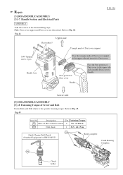
.... Description Q'ty Fastening Torque 18 M6 x 25 Hex socket head bolt 4 7.8 - 11.8 N.m 400 Drill chuck 1 34.3 - 44.1 N.m 18 Quick Change Drill Chuck (Standard Equipment for HR3210FCT) Barrel complete Crank Housing Complete 400 Chuck holder Lower side [3] DISASSEMBLY/ASSEMBLY [3] -8. Handle Section and Electrical Parts ASSEMBLY Take the reverse of Dust cover support...
.... Description Q'ty Fastening Torque 18 M6 x 25 Hex socket head bolt 4 7.8 - 11.8 N.m 400 Drill chuck 1 34.3 - 44.1 N.m 18 Quick Change Drill Chuck (Standard Equipment for HR3210FCT) Barrel complete Crank Housing Complete 400 Chuck holder Lower side [3] DISASSEMBLY/ASSEMBLY [3] -8. Handle Section and Electrical Parts ASSEMBLY Take the reverse of Dust cover support...
Technical Reference
Page 21
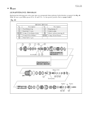
...portions. Tool holder Chuck assembly for HR3210FCT Chuck Section for Piston) Steel ball 6: 3 pcs. See Fig. 44. Repair P 21 / 24 [4] MAINTENANCE PROGRAM Replacing the following parts at the same time is recommended when replacing Carbon brushes is required. Note: Be sure to put Makita grease R No. 00 and N... No. 2 to pages 2 and 3. Description Tool Holder Cap 3 Ring Spring 19 Steel ball 7: 2 pcs. 7 Guide washer O ring 15 (for Impact bolt) 28 Fluoro carbon resin ring 20 O ring 18 (for Striker) 42 46 O ring 18 (for HR3200C, HR3210C Impact bolt...
...portions. Tool holder Chuck assembly for HR3210FCT Chuck Section for Piston) Steel ball 6: 3 pcs. See Fig. 44. Repair P 21 / 24 [4] MAINTENANCE PROGRAM Replacing the following parts at the same time is recommended when replacing Carbon brushes is required. Note: Be sure to put Makita grease R No. 00 and N... No. 2 to pages 2 and 3. Description Tool Holder Cap 3 Ring Spring 19 Steel ball 7: 2 pcs. 7 Guide washer O ring 15 (for Impact bolt) 28 Fluoro carbon resin ring 20 O ring 18 (for Striker) 42 46 O ring 18 (for HR3200C, HR3210C Impact bolt...

Technical Reference
Page 23
Do not put Lead wire of Light circuit on left. Circuit diagram HR3210FCT Fig. Fix it between LED curcuit and Lead wire holder. P 23 / 24 Handle with Lead wire holder. LED Circuit Motor Housing (Rear View) Motor Housing (...
Do not put Lead wire of Light circuit on left. Circuit diagram HR3210FCT Fig. Fix it between LED curcuit and Lead wire holder. P 23 / 24 Handle with Lead wire holder. LED Circuit Motor Housing (Rear View) Motor Housing (...

Technical Reference
Page 24
D-5 Controller Motor housing P 24 / 24 Do not slack the lead wires in this area. Lead unit Route the lead wires of Lead unit through the opening of Power supply cord on the Ribs (A) and (B). Wiring diagram HR3210FCT Fig. Switch Handle Lead wire holder (A) Rib for Controller Dial (B) Rib of Motor housing Lead wire of Power supply cord Power supply cord Handle base Rib Cord guard Connector of Lead unit Do not put the lead wires of Handle base and Handle. Fix them with Lead wire holders and Ribs.
D-5 Controller Motor housing P 24 / 24 Do not slack the lead wires in this area. Lead unit Route the lead wires of Lead unit through the opening of Power supply cord on the Ribs (A) and (B). Wiring diagram HR3210FCT Fig. Switch Handle Lead wire holder (A) Rib for Controller Dial (B) Rib of Motor housing Lead wire of Power supply cord Power supply cord Handle base Rib Cord guard Connector of Lead unit Do not put the lead wires of Handle base and Handle. Fix them with Lead wire holders and Ribs.