
Parts Breakdown
Page 2
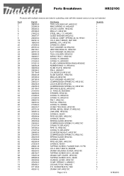
BOLT M6X25, HM1100C BARREL CPL. Parts Breakdown HR3210C Products with multiple versions are listed in subsiding order with the newest version on top not indented Fig # 2 3 4 5 6 7 8 18 19 20 21 22...-9 265995-6 450249-6 233436-0 450250-1 911128-8 450241-2 Part Name TOOL HOLDER CAP, HR3210C RING SPRING 19, HR2450F CHUCK COVER, HR3210C RING 21, HR3210C STEEL BALL 7.0, HR2400 GUIDE WASHER,HR3210C CONICAL COMP. HR3210C O RING 53, AN451 FLAT WASHER 34,HR3210C URETHAN RING 34, HR3210C FLAT WASHER 34,HR3210C TOOL HOLDER, HR3210C IMPACT BOLT, HR3210C O RING 15, HR3000C O RING 15, HR3000C FLURO...
BOLT M6X25, HM1100C BARREL CPL. Parts Breakdown HR3210C Products with multiple versions are listed in subsiding order with the newest version on top not indented Fig # 2 3 4 5 6 7 8 18 19 20 21 22...-9 265995-6 450249-6 233436-0 450250-1 911128-8 450241-2 Part Name TOOL HOLDER CAP, HR3210C RING SPRING 19, HR2450F CHUCK COVER, HR3210C RING 21, HR3210C STEEL BALL 7.0, HR2400 GUIDE WASHER,HR3210C CONICAL COMP. HR3210C O RING 53, AN451 FLAT WASHER 34,HR3210C URETHAN RING 34, HR3210C FLAT WASHER 34,HR3210C TOOL HOLDER, HR3210C IMPACT BOLT, HR3210C O RING 15, HR3000C O RING 15, HR3000C FLURO...
Parts Breakdown
Page 3
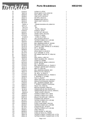
...-6 CARBON BRUSH SET CB-350, HR4001C 1 123 450253-5 REAR COVER. Parts Breakdown HR3210C 75 213223-3 O RING 16, AF502 1 76 158437-6 SPUR GEAR 33 CPL,HR3210C 1 77 424064-4 SEAL RING B, HR3210C 1 78 345868-0 LINK PLATE, HR3210C 1 79 450247-0 AIR PIPE, HR3210C 1 80 263005-3 RUBBER PIN 6,LS1013 2 81 450242-0 GEAR SHAFT,HR3210C 1 81 452126-8 N/A 1 82 158531-4 CRANK HOUSING CPL...
...-6 CARBON BRUSH SET CB-350, HR4001C 1 123 450253-5 REAR COVER. Parts Breakdown HR3210C 75 213223-3 O RING 16, AF502 1 76 158437-6 SPUR GEAR 33 CPL,HR3210C 1 77 424064-4 SEAL RING B, HR3210C 1 78 345868-0 LINK PLATE, HR3210C 1 79 450247-0 AIR PIPE, HR3210C 1 80 263005-3 RUBBER PIN 6,LS1013 2 81 450242-0 GEAR SHAFT,HR3210C 1 81 452126-8 N/A 1 82 158531-4 CRANK HOUSING CPL...
Parts Breakdown
Page 4
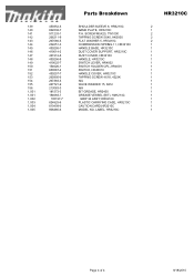
...-7 265995-6 267383-3 267721-9 213083-3 181573-3 194683-7 135197-7 824825-6 810409-6 806480-6 Parts Breakdown SHOULDER SLEEVE 6, HR3210C NAME PLATE, HR3210C P.H. LABEL, HR3210C HR3210C 2 1 2 2 2 1 1 1 1 1 1 1 1 1 1 1 1 1 1 1 1 1 1 1 Page 4 of 4 8/18/2010 SCREW M5X20, TW1000 TAPPING SCREW 5X40, HK0500 FLAT WASHER 5, HR3210C COMPRESSION SPRING 11, HR3210C HANDLE BASE, HR3210C DUST COVER SUPPORT, HR3210C DUST COVER, HR3210C HANDLE, HR3210C SWITCH LEVER, HR4002 SWITCH HOLDER CPL.,HR4001 SWITCH, HR4001C HANDLE...
...-7 265995-6 267383-3 267721-9 213083-3 181573-3 194683-7 135197-7 824825-6 810409-6 806480-6 Parts Breakdown SHOULDER SLEEVE 6, HR3210C NAME PLATE, HR3210C P.H. LABEL, HR3210C HR3210C 2 1 2 2 2 1 1 1 1 1 1 1 1 1 1 1 1 1 1 1 1 1 1 1 Page 4 of 4 8/18/2010 SCREW M5X20, TW1000 TAPPING SCREW 5X40, HK0500 FLAT WASHER 5, HR3210C COMPRESSION SPRING 11, HR3210C HANDLE BASE, HR3210C DUST COVER SUPPORT, HR3210C DUST COVER, HR3210C HANDLE, HR3210C SWITCH LEVER, HR4002 SWITCH HOLDER CPL.,HR4001 SWITCH, HR4001C HANDLE...

Technical Reference
Page 2
...shank bit for M6 Removing Hex socket head bolt M6x25 for tightening Barrel complete 1R259 Taper sleeve Fitting Fluoride ring to protect parts and product from Gear housing 1R346 Center attachment for 1R045 1R212 Tip for Retaining ring pliers Tip for safety before repair/ ...Outer surface Between Striker and Piston in accordance with the black triangle to Impact bolt 1R269 Bearing extractor Removing Ball bearings [2] LUBRICATION Apply Makita grease R. Repair P 2 /24 CAUTION: Unplug the tool and remove the bit for Retaining ring pliers 1R288 Screwdriver magnetizer Magnetizing ...
...shank bit for M6 Removing Hex socket head bolt M6x25 for tightening Barrel complete 1R259 Taper sleeve Fitting Fluoride ring to protect parts and product from Gear housing 1R346 Center attachment for 1R045 1R212 Tip for Retaining ring pliers Tip for safety before repair/ ...Outer surface Between Striker and Piston in accordance with the black triangle to Impact bolt 1R269 Bearing extractor Removing Ball bearings [2] LUBRICATION Apply Makita grease R. Repair P 2 /24 CAUTION: Unplug the tool and remove the bit for Retaining ring pliers 1R288 Screwdriver magnetizer Magnetizing ...
Technical Reference
Page 3
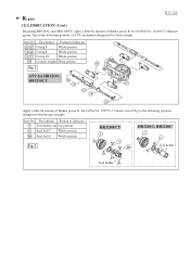
.../ 24 [2] LUBRICATION (Cont.) Regarding HR3210C and HR3210FCT, apply a little bit amount of Makita grease N. Description Portion to the following portions of AVT mechanism designated by black triangle. Description Portion to the following portions designated with the gray triangle. No.2 (Part No. 181573-3: Grease vessel 93g)...ring 18 Whole portion 58 Counter weight Drum portion 50 Fig. 2 AVT for HR3210C, HR3210CT 52 55 63 57 58 61 Apply a little bit amount of Makita grease R. Item No. No.00 (Part No. 181490-7: Hammer grease 30g) to lubricate 2 Tool holder cap Lip ...
.../ 24 [2] LUBRICATION (Cont.) Regarding HR3210C and HR3210FCT, apply a little bit amount of Makita grease N. Description Portion to the following portions of AVT mechanism designated by black triangle. Description Portion to the following portions designated with the gray triangle. No.2 (Part No. 181573-3: Grease vessel 93g)...ring 18 Whole portion 58 Counter weight Drum portion 50 Fig. 2 AVT for HR3210C, HR3210CT 52 55 63 57 58 61 Apply a little bit amount of Makita grease R. Item No. No.00 (Part No. 181490-7: Hammer grease 30g) to lubricate 2 Tool holder cap Lip ...
Technical Reference
Page 6
... assembly is removed so as not to press Washer 28 until it is as illustrated in Fig. 11. Repair P 6 /24 [3] DISASSEMBLY/ASSEMBLY [3] -1A. The rear parts can be removed. And disassemble the front Parts as illustrated in Figs. 9 and 10. Fig. 8 Disassemble as illustrated in Figs. 9 and 10.
... assembly is removed so as not to press Washer 28 until it is as illustrated in Fig. 11. Repair P 6 /24 [3] DISASSEMBLY/ASSEMBLY [3] -1A. The rear parts can be removed. And disassemble the front Parts as illustrated in Figs. 9 and 10. Fig. 8 Disassemble as illustrated in Figs. 9 and 10.
Technical Reference
Page 10
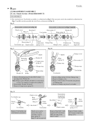
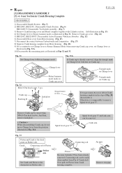
... Flat washer 40 Slide sleeve Fig. 19 Rubber ring 13 Slide plate Cylinder 25 Remove Rubber ring 13. Cylinder Section P 10 / 24 DISASSEMBLY 1) HR3200C, HR3210C: Disassemble Chuck section. (Figs. 5 and 6) HR3210FCT: Disassemble Tool holder assembly. (Figs. 5 and 7) 2) After removing Crank housing cover, disassemble Barrel complete...complete. (Fig. 13) 3) Separate Tool holder section (Tool holder guide section) from Cylinder section. (Figs. 14 and 14A) 4) The parts on Cylinder 25 can be removed as illustrated in Fig. 18. 5) Disassemble Rubber ring 13 and Slide plate from Cylinder 25.
... Flat washer 40 Slide sleeve Fig. 19 Rubber ring 13 Slide plate Cylinder 25 Remove Rubber ring 13. Cylinder Section P 10 / 24 DISASSEMBLY 1) HR3200C, HR3210C: Disassemble Chuck section. (Figs. 5 and 6) HR3210FCT: Disassemble Tool holder assembly. (Figs. 5 and 7) 2) After removing Crank housing cover, disassemble Barrel complete...complete. (Fig. 13) 3) Separate Tool holder section (Tool holder guide section) from Cylinder section. (Figs. 14 and 14A) 4) The parts on Cylinder 25 can be removed as illustrated in Fig. 18. 5) Disassemble Rubber ring 13 and Slide plate from Cylinder 25.
Technical Reference
Page 11
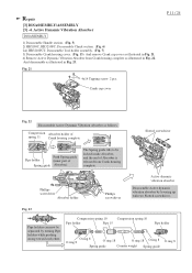
... Pipe holders while pushing strong toward each other. Compression Absorber holder of spring 11 Crank housing complete Slotted screwdriver Pipe holder Push Spring guide (inner part of Absorber is released from Crank housing complete as illustrated in Fig. 23. Active Dynamic Vibration Absorber DISASSEMBLY 1) Disassemble Handle section. (Fig. 5) 2) HR3200C, HR3210FC: Disassemble...
... Pipe holders while pushing strong toward each other. Compression Absorber holder of spring 11 Crank housing complete Slotted screwdriver Pipe holder Push Spring guide (inner part of Absorber is released from Crank housing complete as illustrated in Fig. 23. Active Dynamic Vibration Absorber DISASSEMBLY 1) Disassemble Handle section. (Fig. 5) 2) HR3200C, HR3210FC: Disassemble...
Technical Reference
Page 15
... Change lever to Rotary Hammer Mode when removing Crank cap cover, set Change lever as illustrated in Fig. 31A. 10) Disassemble the remaining parts as illustrated in Fig. 31A. Now pull out Piston from Motor housing. (Fig. 28) 9) If it . Fig. 31A If Crank... cap by unscrewing M4x16 Pan head screws. Gear Section in Crank Housing Complete P 15 / 24 DISASSEMBLY 1) Disassemble Handle Section (Fig. 5) 2) HR3200C, HR3210C: Disassemble Chuck Section (Fig. 6) HR3210FCT: Disassemble Tool holder assembly. (Fig. 7) 3) Remove Crank housing cover and Barrel complete together with that on Crank...
... Change lever to Rotary Hammer Mode when removing Crank cap cover, set Change lever as illustrated in Fig. 31A. 10) Disassemble the remaining parts as illustrated in Fig. 31A. Now pull out Piston from Motor housing. (Fig. 28) 9) If it . Fig. 31A If Crank... cap by unscrewing M4x16 Pan head screws. Gear Section in Crank Housing Complete P 15 / 24 DISASSEMBLY 1) Disassemble Handle Section (Fig. 5) 2) HR3200C, HR3210C: Disassemble Chuck Section (Fig. 6) HR3210FCT: Disassemble Tool holder assembly. (Fig. 7) 3) Remove Crank housing cover and Barrel complete together with that on Crank...
Technical Reference
Page 18
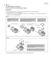
... the reverse of Link arm. Spiral bevel gear 37 Notches of The notches of Link arm Link arm come into this hole. 6) Assemble the remaining parts by fitting its bosses to designate the mark of Link arm come into Crank housing complete until the notches of Rotary hammer mode on Change...
... the reverse of Link arm. Spiral bevel gear 37 Notches of The notches of Link arm Link arm come into this hole. 6) Assemble the remaining parts by fitting its bosses to designate the mark of Link arm come into Crank housing complete until the notches of Rotary hammer mode on Change...
Technical Reference
Page 19
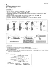
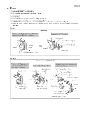
...HR3210C HR3210FCT Replace ON-OFF Switch etc. Handle Section can be disassembled as illustrated in Fig. 41A. Switch lever Switch holder complete Handle Handle cover 4x18 Tapping screw : 1 pc. Handle cover 4x18 Tapping screw: 1 pc. Fig. 41 HR3200C Unscrew 4x18 Tapping screw. Handle Section and Electrical Parts ...Fig. 41A Unscrew 4x18 Tapping screw. Shoulder sleeve 6: 2 pcs. ON-OFF Switch can be replaced as illustrated in Fig. 41. 3A) HR3210C or HR3210FCT: After removing ON-OFF Switch, Handle section can be disassembled as illustrated in Fig. 25 and 26. 2) Controller and Power ...
...HR3210C HR3210FCT Replace ON-OFF Switch etc. Handle Section can be disassembled as illustrated in Fig. 41A. Switch lever Switch holder complete Handle Handle cover 4x18 Tapping screw : 1 pc. Handle cover 4x18 Tapping screw: 1 pc. Fig. 41 HR3200C Unscrew 4x18 Tapping screw. Handle Section and Electrical Parts ...Fig. 41A Unscrew 4x18 Tapping screw. Shoulder sleeve 6: 2 pcs. ON-OFF Switch can be replaced as illustrated in Fig. 41. 3A) HR3210C or HR3210FCT: After removing ON-OFF Switch, Handle section can be disassembled as illustrated in Fig. 25 and 26. 2) Controller and Power ...
Technical Reference
Page 20
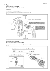
....1 N.m 18 Quick Change Drill Chuck (Standard Equipment for HR3210FCT) Barrel complete Crank Housing Complete 400 Chuck holder Refer to Fig. 42. Handle Section and Electrical Parts ASSEMBLY Take the reverse of Dust cover to the upper side and assemble Dust cover to Handle. Lower side [3] DISASSEMBLY/ASSEMBLY [3] -8. Bow portion of Dust...
....1 N.m 18 Quick Change Drill Chuck (Standard Equipment for HR3210FCT) Barrel complete Crank Housing Complete 400 Chuck holder Refer to Fig. 42. Handle Section and Electrical Parts ASSEMBLY Take the reverse of Dust cover to the upper side and assemble Dust cover to Handle. Lower side [3] DISASSEMBLY/ASSEMBLY [3] -8. Bow portion of Dust...
Technical Reference
Page 21
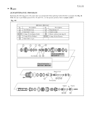
... / 24 [4] MAINTENANCE PROGRAM Replacing the following parts at the same time is recommended when replacing Carbon brushes is required. See Fig. 44. Tool holder Chuck assembly for HR3210FCT Chuck Section for Piston) Steel ball 6: 3 pcs. Fig. 44 No. 2 6 26 27 41 10 HR3200C, HR3210C Description No. Description Tool Holder Cap 3 Ring...2 pcs. 7 Guide washer O ring 15 (for Impact bolt) 28 Fluoro carbon resin ring 20 O ring 18 (for Striker) 42 46 O ring 18 (for HR3200C, HR3210C Impact bolt Tool holder Striker Piston Refer to the specific portions. Note: Be sure to put...
... / 24 [4] MAINTENANCE PROGRAM Replacing the following parts at the same time is recommended when replacing Carbon brushes is required. See Fig. 44. Tool holder Chuck assembly for HR3210FCT Chuck Section for Piston) Steel ball 6: 3 pcs. Fig. 44 No. 2 6 26 27 41 10 HR3200C, HR3210C Description No. Description Tool Holder Cap 3 Ring...2 pcs. 7 Guide washer O ring 15 (for Impact bolt) 28 Fluoro carbon resin ring 20 O ring 18 (for Striker) 42 46 O ring 18 (for HR3200C, HR3210C Impact bolt Tool holder Striker Piston Refer to the specific portions. Note: Be sure to put...


