
Technical Reference
Page 1
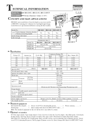
...speed control Double insulation Power supply cord (m: ft) Net weight: kg (lbs) HR3200C HR3210C HR3210FCT 315 - 630 1,650 - 3,300 SDS-plus 32 (1-1/4) 90 (3-1/2) 13 (1/2) 32 (1-1/4) 3 modes (Rotation only/ Rotation with Hammering/ Hammering only) Yes Yes Yes Yes Yes Europe: 4.0 (13.1), Brazil: 2.0 (6.6), Other ...chuck (for HR3210FCT only) ..... 1 Note: The standard equipment for HR3210FCT only) HR3200C, HR3210C, HR3210FCT Description Rotary Hammer 32mm (1-1/4") CONCEPT AND MAIN APPLICATIONS PRODUCT P 1/ 24 L H HR3200C series models have been developed as successor models of...
...speed control Double insulation Power supply cord (m: ft) Net weight: kg (lbs) HR3200C HR3210C HR3210FCT 315 - 630 1,650 - 3,300 SDS-plus 32 (1-1/4) 90 (3-1/2) 13 (1/2) 32 (1-1/4) 3 modes (Rotation only/ Rotation with Hammering/ Hammering only) Yes Yes Yes Yes Yes Europe: 4.0 (13.1), Brazil: 2.0 (6.6), Other ...chuck (for HR3210FCT only) ..... 1 Note: The standard equipment for HR3210FCT only) HR3200C, HR3210C, HR3210FCT Description Rotary Hammer 32mm (1-1/4") CONCEPT AND MAIN APPLICATIONS PRODUCT P 1/ 24 L H HR3200C series models have been developed as successor models of...
Technical Reference
Page 15
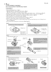
... Crank Connecting rod of Piston Striker side Set Crank and Piston to Rotary hammer mode. And then, remove Link plate. < Caution > When disassembling Crank cap, do not move Change lever from Crank housing complete. Remove Crank cap cover. (Fig. 21) 5) HR3210C, HR3210FCT: Disassemble Active Dynamic Vibration Absorber. (Fig. 22) 6) Disassemble Rear cover from...
... Crank Connecting rod of Piston Striker side Set Crank and Piston to Rotary hammer mode. And then, remove Link plate. < Caution > When disassembling Crank cap, do not move Change lever from Crank housing complete. Remove Crank cap cover. (Fig. 21) 5) HR3210C, HR3210FCT: Disassemble Active Dynamic Vibration Absorber. (Fig. 22) 6) Disassemble Rear cover from...
Technical Reference
Page 17
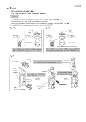
Gear Section in Fig. 37. And then, mount the Crank section to assemble the Gear unit in Rotary hammer mode exactly. Note: When assembling Retaining ring WR-10 to Crank shaft, assemble it is removed easily. Fig. 37 Crank gear Gear shaft These notches ...
Gear Section in Fig. 37. And then, mount the Crank section to assemble the Gear unit in Rotary hammer mode exactly. Note: When assembling Retaining ring WR-10 to Crank shaft, assemble it is removed easily. Fig. 37 Crank gear Gear shaft These notches ...
Technical Reference
Page 18
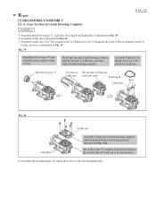
... Fig. 40. 5) Assemble Crank cap cover. Seal ring B Boss Link plate Fig. 40 Crank cap Link plate Assemble Crank cap to designate the mark of Rotary hammer mode on Change lever has to Crank housing complete while keeping Change lever in the position illustrated in Fig. 31. Assemble Link plate by taking...
... Fig. 40. 5) Assemble Crank cap cover. Seal ring B Boss Link plate Fig. 40 Crank cap Link plate Assemble Crank cap to designate the mark of Rotary hammer mode on Change lever has to Crank housing complete while keeping Change lever in the position illustrated in Fig. 31. Assemble Link plate by taking...

