Owners Manual
Page 2
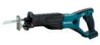
...; Due to change without notice. • Note: Specifications may result in all instructions. Power tools create sparks which may result in the presence of electric shock. Keep children and bystanders away while operating a power tool. Do not expose power tools to a rotating part of electric shock. 7. Do not abuse the cord. Never use the cord for outdoor use any adapter plugs with your mains-operated (corded) power tool or battery-operated (cordless) power tool. Keep cord away from...
...; Due to change without notice. • Note: Specifications may result in all instructions. Power tools create sparks which may result in the presence of electric shock. Keep children and bystanders away while operating a power tool. Do not expose power tools to a rotating part of electric shock. 7. Do not abuse the cord. Never use the cord for outdoor use any adapter plugs with your mains-operated (corded) power tool or battery-operated (cordless) power tool. Keep cord away from...
Owners Manual
Page 3
... operation where the cutting tool may create a risk of battery pack may contact hidden wiring or its own cord. A charger that the safety of moving parts. Inspect workpiece for your hair, clothing, and gloves away from repeated use . Do not force the power tool. If damaged, have the switch on and off position before making any nails and remove them before use ) replace strict adherence to be repaired...
... operation where the cutting tool may create a risk of battery pack may contact hidden wiring or its own cord. A charger that the safety of moving parts. Inspect workpiece for your hair, clothing, and gloves away from repeated use . Do not force the power tool. If damaged, have the switch on and off position before making any nails and remove them before use ) replace strict adherence to be repaired...
Owners Manual
Page 4
... come to water or rain. V volts direct current no -load unnecessarily. 14. Do not disassemble battery cartridge. 3. Let a hot battery cartridge cool down before completely discharged. Make sure the blade is not contacting the workpiece before the switch is removed before removing the blade from moving parts. 10. Always switch off and the battery cartridge is turned on (1) battery charger, (2) battery, and (3) product using battery. 2. It may result in...
... come to water or rain. V volts direct current no -load unnecessarily. 14. Do not disassemble battery cartridge. 3. Let a hot battery cartridge cool down before completely discharged. Make sure the blade is not contacting the workpiece before the switch is removed before removing the blade from moving parts. 10. Always switch off and the battery cartridge is turned on (1) battery charger, (2) battery, and (3) product using battery. 2. It may result in...
Owners Manual
Page 5
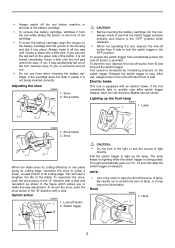
... locks in the light or see that the switch trigger actuates properly and returns to the "OFF" position when released. • When not operating the tool, depress the lock-off button from A side to stop after the switch trigger is increased by increasing pressure on lighting while the switch trigger is not being pulled. Adjusting the shoe 006898 1. Switch action 006900 1 1. Hook 006902 1. After use force when inserting the battery cartridge. Lighting...
... locks in the light or see that the switch trigger actuates properly and returns to the "OFF" position when released. • When not operating the tool, depress the lock-off button from A side to stop after the switch trigger is increased by increasing pressure on lighting while the switch trigger is not being pulled. Adjusting the shoe 006898 1. Switch action 006900 1 1. Hook 006902 1. After use force when inserting the battery cartridge. Lighting...
Owners Manual
Page 6
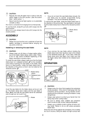
... tool to lock the switch trigger in a serious injury. NOTE: • If you try to the blade, blade clamp and/or slider. To install the saw blade, always make sure that the blade clamp lever locked at the released position . 006665 1. Blade clamp sleeve 2. Fixed position 1 NOTE: • If you remove the saw blade. Bring the blade into light contact with current national standards. • Always use a suitable coolant (cutting oil) when cutting metal. The hook is removed...
... tool to lock the switch trigger in a serious injury. NOTE: • If you try to the blade, blade clamp and/or slider. To install the saw blade, always make sure that the blade clamp lever locked at the released position . 006665 1. Blade clamp sleeve 2. Fixed position 1 NOTE: • If you remove the saw blade. Bring the blade into light contact with current national standards. • Always use a suitable coolant (cutting oil) when cutting metal. The hook is removed...
Owners Manual
Page 7
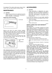
... maintenance. Use only identical carbon brushes. Screwdriver 1 2 After replacing brushes, insert the battery cartridge into the tool and break in this one of Makita's Factory or Authorized Service Centers. Should any other maintenance or adjustment should be performed by running and electric brake operation when releasing the switch trigger. MAKITA DISCLAIMS LIABILITY FOR ANY IMPLIED WARRANTIES, INCLUDING IMPLIED WARRANTIES OF "MERCHANTABILITY" AND "FITNESS FOR A SPECIFIC PURPOSE," AFTER THE ONE YEAR TERM OF THIS WARRANTY. MAINTENANCE...
... maintenance. Use only identical carbon brushes. Screwdriver 1 2 After replacing brushes, insert the battery cartridge into the tool and break in this one of Makita's Factory or Authorized Service Centers. Should any other maintenance or adjustment should be performed by running and electric brake operation when releasing the switch trigger. MAKITA DISCLAIMS LIABILITY FOR ANY IMPLIED WARRANTIES, INCLUDING IMPLIED WARRANTIES OF "MERCHANTABILITY" AND "FITNESS FOR A SPECIFIC PURPOSE," AFTER THE ONE YEAR TERM OF THIS WARRANTY. MAINTENANCE...
Parts Breakdown
Page 2
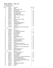
... WASHER 14 1 PC. 41 232222-6 LEAF SPRING B 1 PC. 42 345479-1 SHOE GUIDE 1 PC. 43 265165-7 TORXSOCKET C.S.HEADSCREW M6X16 1 PC. 44 266041-8 TAPPING SCREW 5X25 4 PC. 45 154812-4 GEAR HOUSING COMPLETE 1 46 912207-5 COUNTERSUNK HEAD SCREW M5X10 2 PC. 47 951057-3 SPRING PIN 3-12 1 PC. 48 313127-0 JOINT 1 49 233455-6 COMPRESSION SPRING 7 1 50 262561-0 SLEEVE 6 1 51 281218-4 HOOK 1 Model BJR181 Parts List A = Standard Equipment O = Circuit Diagram...
... WASHER 14 1 PC. 41 232222-6 LEAF SPRING B 1 PC. 42 345479-1 SHOE GUIDE 1 PC. 43 265165-7 TORXSOCKET C.S.HEADSCREW M6X16 1 PC. 44 266041-8 TAPPING SCREW 5X25 4 PC. 45 154812-4 GEAR HOUSING COMPLETE 1 46 912207-5 COUNTERSUNK HEAD SCREW M5X10 2 PC. 47 951057-3 SPRING PIN 3-12 1 PC. 48 313127-0 JOINT 1 49 233455-6 COMPRESSION SPRING 7 1 50 262561-0 SLEEVE 6 1 51 281218-4 HOOK 1 Model BJR181 Parts List A = Standard Equipment O = Circuit Diagram...
Parts Breakdown
Page 3
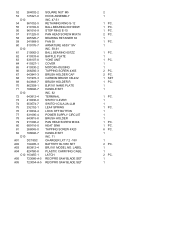
...-A-5 SQUARE NUT M5 HOOK ASSEMBLY INC. 47-51 RETAINING RING S-12 BALL BEARING 6001DDW STOP RING E-10 PAN HEAD SCREW M5X16 BEARING RETAINER 63 FAN 55 ARMATURE ASSY 18V INC. 59,61 BALL BEARING 607ZZ BAFFLE PLATE YOKE UNIT COVER MOTOR HOUSING TAPPING SCREW 4X65 BRUSH HOLDER CAP CARBON BRUSH CB-432 BRUSH HOLDER R BJR181 NAME PLATE HANDLE SET INC. 82 TERMINAL SWITCH LEVER SWITCH C3LA-2A-LLM LEAF SPRING LOCK OFF BUTTON POWER SUPPLY...
...-A-5 SQUARE NUT M5 HOOK ASSEMBLY INC. 47-51 RETAINING RING S-12 BALL BEARING 6001DDW STOP RING E-10 PAN HEAD SCREW M5X16 BEARING RETAINER 63 FAN 55 ARMATURE ASSY 18V INC. 59,61 BALL BEARING 607ZZ BAFFLE PLATE YOKE UNIT COVER MOTOR HOUSING TAPPING SCREW 4X65 BRUSH HOLDER CAP CARBON BRUSH CB-432 BRUSH HOLDER R BJR181 NAME PLATE HANDLE SET INC. 82 TERMINAL SWITCH LEVER SWITCH C3LA-2A-LLM LEAF SPRING LOCK OFF BUTTON POWER SUPPLY...


