Owners Manual
Page 1
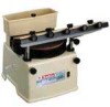
Overall length 390 mm (15-3/8") Net weight 1 1 kg (24.3 Ibs) Sharpener 200 mm (7-718") MODEL 9820-2 INSTRUCTION MANUAL SPECIFICATIONS Wheel size 200 m m x 25 mm x 75 m m (7-7/8" x 1" x 3") No load speed 560 R/min.
Overall length 390 mm (15-3/8") Net weight 1 1 kg (24.3 Ibs) Sharpener 200 mm (7-718") MODEL 9820-2 INSTRUCTION MANUAL SPECIFICATIONS Wheel size 200 m m x 25 mm x 75 m m (7-7/8" x 1" x 3") No load speed 560 R/min.
Owners Manual
Page 2
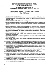
.... 3.REMOVE ADJUSTING KEYS AND WRENCHES. Also use power tools in . ation is recommended. Everyday eyeglasses only have read all times. . 14.MAINTAIN TOOLS WITH CARE. when changing accessories such as the specific potential hazards peculiar t o it on. 4. Read the owner's manual carefully. accidents. 5. All visitors should be kept safe distance from tool before turning it . 2. It will do a job for which it frees both hands t o operate tool. 13. Keep tools...
.... 3.REMOVE ADJUSTING KEYS AND WRENCHES. Also use power tools in . ation is recommended. Everyday eyeglasses only have read all times. . 14.MAINTAIN TOOLS WITH CARE. when changing accessories such as the specific potential hazards peculiar t o it on. 4. Read the owner's manual carefully. accidents. 5. All visitors should be kept safe distance from tool before turning it . 2. It will do a job for which it frees both hands t o operate tool. 13. Keep tools...
Owners Manual
Page 3
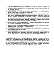
... the operator from electric shock. 23. Replace or repair damaged or worn cord immediately. VOLTAGE WARNING: Before connecting the tool t o a power source (receptacle, outlet, etc.) be properly repaired or replaced. 20. Consult the owner's manual for the tool can result in SERIOUS INJURY t o the user - If in use of the blade or cutter only. 21. TURN POWER OFF. Don't leave tool until it will operate properly and perform its operation. A power...
... the operator from electric shock. 23. Replace or repair damaged or worn cord immediately. VOLTAGE WARNING: Before connecting the tool t o a power source (receptacle, outlet, etc.) be properly repaired or replaced. 20. Consult the owner's manual for the tool can result in SERIOUS INJURY t o the user - If in use of the blade or cutter only. 21. TURN POWER OFF. Don't leave tool until it will operate properly and perform its operation. A power...
Owners Manual
Page 4
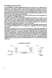
GROUNDING INSTRUCTIONS ALL GROUNDED, CORD-CONNECTED TOOLS: In the event of a malfunction or breakdown, grounding provides a path of least resistance for use on a circuit that has an outlet that looks like the one illustrated in Figure A. ance with an electric cord hav- Check with a qualified electrician or serviceman if the grounding instructions are not completely understood, or if in...
GROUNDING INSTRUCTIONS ALL GROUNDED, CORD-CONNECTED TOOLS: In the event of a malfunction or breakdown, grounding provides a path of least resistance for use on a circuit that has an outlet that looks like the one illustrated in Figure A. ance with an electric cord hav- Check with a qualified electrician or serviceman if the grounding instructions are not completely understood, or if in...
Owners Manual
Page 5
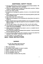
... rotating parts. 7. Replace cracked or damaged wheel immediately. 3. Be careful not t o damage the spindle or the bolt, or the wheel itself might be - Before using the tool on the tool's nameplate. 2. Do not overtighten wheel nut. 6. Keep hands away from freezing in a dry location only. Freezing can crack the wheel. 14. Use only flanges furnished with the grinder. 5 WARNING For Your Own Safety Read Instruction Manual Before Operating Grinder 1.
... rotating parts. 7. Replace cracked or damaged wheel immediately. 3. Be careful not t o damage the spindle or the bolt, or the wheel itself might be - Before using the tool on the tool's nameplate. 2. Do not overtighten wheel nut. 6. Keep hands away from freezing in a dry location only. Freezing can crack the wheel. 14. Use only flanges furnished with the grinder. 5 WARNING For Your Own Safety Read Instruction Manual Before Operating Grinder 1.
Owners Manual
Page 6
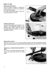
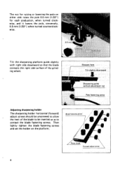
... TO USE Replacing grinding wheel Use the wrench provided to release the grinding wheel by turning the guard clockwiseto lower it, or counterclockwise to raise it. To install the grinding wheel, follow the removal procedure in reverse. Adjusting wheel guard The top of the wheel guard should be 1 mm (approx. 1/3") below the surface of the grinding wheel. Coat the sharpening platform guide and the sharpening holder with machine oil or spindle oil. Removing or installing...
... TO USE Replacing grinding wheel Use the wrench provided to release the grinding wheel by turning the guard clockwiseto lower it, or counterclockwise to raise it. To install the grinding wheel, follow the removal procedure in reverse. Adjusting wheel guard The top of the wheel guard should be 1 mm (approx. 1/3") below the surface of the grinding wheel. Coat the sharpening platform guide and the sharpening holder with machine oil or spindle oil. Removing or installing...
Owners Manual
Page 7
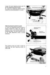
Loosen the pole fastening screws and lift off the sharpening platform guide. To install the sharpening platform guide, follow the removal procedure in place by tightening the pole fastening screws on Pole either side. 7 Sharpening platform guide (Rail) The platform poles are fixed in reverse. Adjusting sharpening platform guide In using the sharpening platform guide to sharpen blade/knife, adjust the angle adjustment screw to the desired blade/knife sharpening angle. The bevel becomes acute as the angle adjustment screw is turned clockwise.
Loosen the pole fastening screws and lift off the sharpening platform guide. To install the sharpening platform guide, follow the removal procedure in place by tightening the pole fastening screws on Pole either side. 7 Sharpening platform guide (Rail) The platform poles are fixed in reverse. Adjusting sharpening platform guide In using the sharpening platform guide to sharpen blade/knife, adjust the angle adjustment screw to the desired blade/knife sharpening angle. The bevel becomes acute as the angle adjustment screw is turned clockwise.
Owners Manual
Page 8
Blade I \ Forward adiurt screw I I I The sharpening holder horizontal (forward) adjust screws should be inserted so as to be unscrewedto allow the heel of the grinding wheel. The nut for raising or lowering the pole on the platform. - Adjusting sharpening holder I \ 8 Then lightly tighten the blade fastening screws and set the holder on either side raises the pole 0.5 mm (1/32") for each graduation, when turned clockwise, and it lowers...
Blade I \ Forward adiurt screw I I I The sharpening holder horizontal (forward) adjust screws should be inserted so as to be unscrewedto allow the heel of the grinding wheel. The nut for raising or lowering the pole on the platform. - Adjusting sharpening holder I \ 8 Then lightly tighten the blade fastening screws and set the holder on either side raises the pole 0.5 mm (1/32") for each graduation, when turned clockwise, and it lowers...
Owners Manual
Page 9
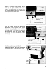
Screw in clockwise the forward adjust screw on the right until the left upper edge of the blade comes into the grooves provided for them on the sharpener frame. 9 Now use all four fastening screws to the right across the sharpening platform guide. Installingcoolant reservoir (Tank) Insert the reservoir legs into contact with the grinding wheel. Then fully tighten the fastening screw on the horizontal. Screw in the left-hand forward adjust screw until the right upper edge of the blade contacts the grinding wheel. Slide the holder to secure the blade on the far right.
Screw in clockwise the forward adjust screw on the right until the left upper edge of the blade comes into the grooves provided for them on the sharpener frame. 9 Now use all four fastening screws to the right across the sharpening platform guide. Installingcoolant reservoir (Tank) Insert the reservoir legs into contact with the grinding wheel. Then fully tighten the fastening screw on the horizontal. Screw in the left-hand forward adjust screw until the right upper edge of the blade contacts the grinding wheel. Slide the holder to secure the blade on the far right.
Owners Manual
Page 10
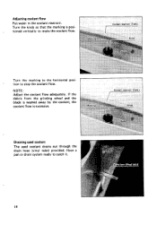
tion to catch it. 10 Have a pan or drain system ready to stop the coolant flow. r Turn the marking to make the coolant flow. If the debris from the grinding wheel and the blade is washed away by the coolant, the coolant flow is excessive. Adjusting coolant flow Put water in the coolant reservoir. Turn the knob so that the marking i s positioned vertically to the horizontal posi- Draining used coolant The used coolant drains out through the drain hose (vinyl tube) provided. NOTE : Adjust the coolant flow adequately.
tion to catch it. 10 Have a pan or drain system ready to stop the coolant flow. r Turn the marking to make the coolant flow. If the debris from the grinding wheel and the blade is washed away by the coolant, the coolant flow is excessive. Adjusting coolant flow Put water in the coolant reservoir. Turn the knob so that the marking i s positioned vertically to the horizontal posi- Draining used coolant The used coolant drains out through the drain hose (vinyl tube) provided. NOTE : Adjust the coolant flow adequately.
Owners Manual
Page 11
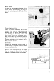
... guide a t a speed of the switch. To turn the tool off, press the OFF side of about ten times per minute, applying uniform pressure (about 11 Ibs) on the front of the tool. about 5 kg; Remove some stock from you can begin sharpening. Sharpening blade/knife 1 After you have established the correct coolant flow, you , holding the sharpening holder with the cutting edge...
... guide a t a speed of the switch. To turn the tool off, press the OFF side of about ten times per minute, applying uniform pressure (about 11 Ibs) on the front of the tool. about 5 kg; Remove some stock from you can begin sharpening. Sharpening blade/knife 1 After you have established the correct coolant flow, you , holding the sharpening holder with the cutting edge...
Owners Manual
Page 12
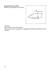
Power planer blade CAUTION : *Clean and dry the tool after operation. 0 Be sure that the tool is switched off, unplugged and drained before attempting to a 40" angle. Sharpening power planer blades Sharpen your planer blades to move the tool. 12
Power planer blade CAUTION : *Clean and dry the tool after operation. 0 Be sure that the tool is switched off, unplugged and drained before attempting to a 40" angle. Sharpening power planer blades Sharpen your planer blades to move the tool. 12
Owners Manual
Page 13
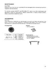
... tool is switched off and unplugged before attempting to persons. The accessories or attachments should be performed by Makita Authorized or Factory Service Centers, always using makita replacement parts. The use with your Makita tool specified i n this manual. Part No. 132386-5 13 MAINTENANCE CAUTION : Always be used only in the proper and intended manner. 0 Grinding wheels Wrench Part No. 341 391 - 3 Size (mm) I Grit I Part No. 200x25~75 (7-7/8" x 1" x 3") 741074-9 Guide assembly (Sharpening platform guide...
... tool is switched off and unplugged before attempting to persons. The accessories or attachments should be performed by Makita Authorized or Factory Service Centers, always using makita replacement parts. The use with your Makita tool specified i n this manual. Part No. 132386-5 13 MAINTENANCE CAUTION : Always be used only in the proper and intended manner. 0 Grinding wheels Wrench Part No. 341 391 - 3 Size (mm) I Grit I Part No. 200x25~75 (7-7/8" x 1" x 3") 741074-9 Guide assembly (Sharpening platform guide...
Owners Manual
Page 14
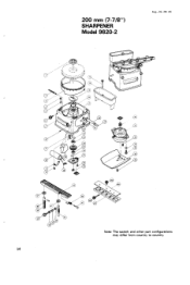
200 mm (7-7/8") SHARPENER Model 9820-2 Aug.-02-84 US Note: The switch and other part configurations may differ from country to country. 14
200 mm (7-7/8") SHARPENER Model 9820-2 Aug.-02-84 US Note: The switch and other part configurations may differ from country to country. 14
Owners Manual
Page 15
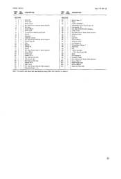
... 1 1 Knob 65 2 1 Vinyl Tube 3 1 Wheel Cover 4 2 Pan Head Screw M5x20 (With Washer) 5 2 set Plate 6 2 Screw M6x31 7 1 Name Plate 8 2 Countersunk Head Screw M3x6 9 1 Switch 10 1 capacotor 11 1 Capacttor Clamp 12 2 Pan Head Screw M5x20 IWith WasHerl 13 1 Thumb Pipe 20 14 1 Tank 15 1 Spindle 16 1 0 Ring 40 17 1 Frame 18 1 Pan Head Screw M4x12 IWith Washell 19 1 Strain Relief 20 1 Cord Guard 22 1 Rubber Pin 4 23 1 Ball Bearlng 6202LLB 24 1 Helical Gear 38...
... 1 1 Knob 65 2 1 Vinyl Tube 3 1 Wheel Cover 4 2 Pan Head Screw M5x20 (With Washer) 5 2 set Plate 6 2 Screw M6x31 7 1 Name Plate 8 2 Countersunk Head Screw M3x6 9 1 Switch 10 1 capacotor 11 1 Capacttor Clamp 12 2 Pan Head Screw M5x20 IWith WasHerl 13 1 Thumb Pipe 20 14 1 Tank 15 1 Spindle 16 1 0 Ring 40 17 1 Frame 18 1 Pan Head Screw M4x12 IWith Washell 19 1 Strain Relief 20 1 Cord Guard 22 1 Rubber Pin 4 23 1 Ball Bearlng 6202LLB 24 1 Helical Gear 38...
Owners Manual
Page 16
... OR USE OF THE PRODUCT. MAKITA DISCLAIMS LIABILITY FOR ANY IMPLIED WARRANTIES, INCLUDING IMPLIED WARRANTIES OF "MERCHANTABILITY" AND "FITNESS FOR A SPECIFIC PURPOSE," AFTER THE ONE-YEAR TERM OF THIS WARRANTY. This Warranty does not apply where: repairs have been made t o the tool. Makita Corporation 3-11-8, Sumiyoshi-cho, Anjo, Aichi 446 Japan 003277 - 062 C PRINTED IN JAPAN 1991 - 8 - Should any trouble develop...
... OR USE OF THE PRODUCT. MAKITA DISCLAIMS LIABILITY FOR ANY IMPLIED WARRANTIES, INCLUDING IMPLIED WARRANTIES OF "MERCHANTABILITY" AND "FITNESS FOR A SPECIFIC PURPOSE," AFTER THE ONE-YEAR TERM OF THIS WARRANTY. This Warranty does not apply where: repairs have been made t o the tool. Makita Corporation 3-11-8, Sumiyoshi-cho, Anjo, Aichi 446 Japan 003277 - 062 C PRINTED IN JAPAN 1991 - 8 - Should any trouble develop...
Parts Breakdown
Page 1
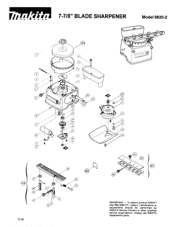
To assure product SAFETY and RELIABILITY. Always use MAKITA replacement parts. repairs, maintenance or adjustments should be performed by MAKITA Service Centers or other qualified service organizations. r r 7-7/8" BLADE SHARPENER Model 9820-2 01-96 IMPORTANT -
To assure product SAFETY and RELIABILITY. Always use MAKITA replacement parts. repairs, maintenance or adjustments should be performed by MAKITA Service Centers or other qualified service organizations. r r 7-7/8" BLADE SHARPENER Model 9820-2 01-96 IMPORTANT -
Parts Breakdown
Page 2
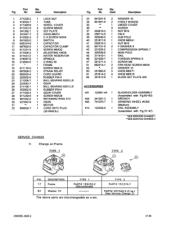
... CHANGE 2 SERVICE CHANGE 1) Change on Frame. No. DESCRIPTION 17 Frame 52 Washer 1 0 TYPE 1 PART# 155220-2 (Discontinued) TYPE 2 PART# 151274-7 PART# 267040-3 (2 ea.) (See Service Change 2) 2 MODEL 9820-2 01-96 Used Description 1 271235-2 1 LOCK NUT 2 412033-7 1 TUBE 3 411429-9 1 WHEEL COVER 4 911231-5 2 SCREW M5X20 5 341392-1 2 SET PLATE 6 251847-7 2 KNOB M6X31 8 912002-3 2 C.H.SCREW M3X6 9 651502-5 1 SWITCH 10 645314-6 1 CAPACITOR 11 687629-5 1 CAPACITOR CLAMP 12 911231-5 2 SCREW M5X20 13 271405-3 1 ADJUSTING KNOB 14 411431-2 1 WATER RESERVOIR 15 314087-9 1 SPINDLE...
... CHANGE 2 SERVICE CHANGE 1) Change on Frame. No. DESCRIPTION 17 Frame 52 Washer 1 0 TYPE 1 PART# 155220-2 (Discontinued) TYPE 2 PART# 151274-7 PART# 267040-3 (2 ea.) (See Service Change 2) 2 MODEL 9820-2 01-96 Used Description 1 271235-2 1 LOCK NUT 2 412033-7 1 TUBE 3 411429-9 1 WHEEL COVER 4 911231-5 2 SCREW M5X20 5 341392-1 2 SET PLATE 6 251847-7 2 KNOB M6X31 8 912002-3 2 C.H.SCREW M3X6 9 651502-5 1 SWITCH 10 645314-6 1 CAPACITOR 11 687629-5 1 CAPACITOR CLAMP 12 911231-5 2 SCREW M5X20 13 271405-3 1 ADJUSTING KNOB 14 411431-2 1 WATER RESERVOIR 15 314087-9 1 SPINDLE...
Parts Breakdown
Page 3
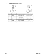
DESCRIPTION 31 Motor 35 Under Cover 36 Screw 52 Washer TYPE 1 PART# 6 2 9 5 10-4 (Discontinued) PART# 3425 16-2 (Discontinued) PART# 91 1104-2 M4x6 (Use 4 ea.) PART# 267040-3 (Discontinued) TYPE 2 PART# 629644-3 PART# 344030-4 PART# 91 1108-4 M4x8 (Use 3 ea.) ____-------- 01-96 3 MODEL 9820-2 2 ) Change on Motor from S/N 30,058E. FIG.
DESCRIPTION 31 Motor 35 Under Cover 36 Screw 52 Washer TYPE 1 PART# 6 2 9 5 10-4 (Discontinued) PART# 3425 16-2 (Discontinued) PART# 91 1104-2 M4x6 (Use 4 ea.) PART# 267040-3 (Discontinued) TYPE 2 PART# 629644-3 PART# 344030-4 PART# 91 1108-4 M4x8 (Use 3 ea.) ____-------- 01-96 3 MODEL 9820-2 2 ) Change on Motor from S/N 30,058E. FIG.


