
User Manual
Page 1
Portable Air Conditioner 8000/10000 BTU User's Manual Model NPPAC8KWM / NPPAC10KWM READ THIS MANUAL CAREFULLY BEFORE USING YOUR PORTABLE AIR CONDITIONER AND KEEP IT FOR FUTURE REFERENCE. 1
Portable Air Conditioner 8000/10000 BTU User's Manual Model NPPAC8KWM / NPPAC10KWM READ THIS MANUAL CAREFULLY BEFORE USING YOUR PORTABLE AIR CONDITIONER AND KEEP IT FOR FUTURE REFERENCE. 1

User Manual
Page 3
CONTENTS PRODUCT REGISTRATION 2 IMPORTANT SAFETY INSTRUCTIONS 4 SPECIFICATIONS 6 PARTS IDENTIFICATION 7 INSTALLATION INSTRUCTIONS 8 REMOTE CONTROL 13 OPERATION INSTRUCTIONS 15 CARE AND MAINTENANCE 18 TROUBLESHOOTING 19 LIMITED WARRANTY 20 3
CONTENTS PRODUCT REGISTRATION 2 IMPORTANT SAFETY INSTRUCTIONS 4 SPECIFICATIONS 6 PARTS IDENTIFICATION 7 INSTALLATION INSTRUCTIONS 8 REMOTE CONTROL 13 OPERATION INSTRUCTIONS 15 CARE AND MAINTENANCE 18 TROUBLESHOOTING 19 LIMITED WARRANTY 20 3
User Manual
Page 4
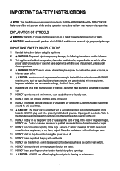
... own while reading operation instructions as a bathroom or laundry room. 8. DO NOT use . If the cord or plug is not able to this type of the floor, away from heat sources or anywhere it will not be performed according to cleaning or maintenance. 4 Important Safety Instructions NOTE: This User Manual encompasses information for replacement or repair. 12. Make note of the unit. 9. IMPORTANT SAFETY INSTRUCTIONS 1. Read all...
... own while reading operation instructions as a bathroom or laundry room. 8. DO NOT use . If the cord or plug is not able to this type of the floor, away from heat sources or anywhere it will not be performed according to cleaning or maintenance. 4 Important Safety Instructions NOTE: This User Manual encompasses information for replacement or repair. 12. Make note of the unit. 9. IMPORTANT SAFETY INSTRUCTIONS 1. Read all...
User Manual
Page 5
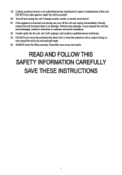
... THESE INSTRUCTIONS 5 Doing so may cause the unit to ensure there is full, or force the castors to take apart or repair the unit by yourself. 20. Clean filter once every two weeks. DO NOT try to move the unit when the tank is no damage. Contact customer service or an authorized service technician for assistance. 22. Turn off the unit and...
... THESE INSTRUCTIONS 5 Doing so may cause the unit to ensure there is full, or force the castors to take apart or repair the unit by yourself. 20. Clean filter once every two weeks. DO NOT try to move the unit when the tank is no damage. Contact customer service or an authorized service technician for assistance. 22. Turn off the unit and...
User Manual
Page 6
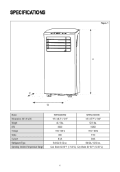
R410A / 10.58 oz. Cool Mode: 62-95°F (17-35°C) / Dry Mode: 55-95°F (13-35°C) 6 SPECIFICATIONS Figure 1 H D W Model Dimensions (W x H x D) Weight BTU Voltage Watts Current Refrigerant Type Operating Ambient Temperature Range NPPAC8KWM NPPAC10KWM 13" x 24.2" x 12.5" 14" x 27.7" x 13.6" 44.1 lbs. 52.9 lbs. 8000 10000 115V / 60Hz 115V / 60Hz 900 1110 8.5A 9.8A R410A / 9.52 oz.
R410A / 10.58 oz. Cool Mode: 62-95°F (17-35°C) / Dry Mode: 55-95°F (13-35°C) 6 SPECIFICATIONS Figure 1 H D W Model Dimensions (W x H x D) Weight BTU Voltage Watts Current Refrigerant Type Operating Ambient Temperature Range NPPAC8KWM NPPAC10KWM 13" x 24.2" x 12.5" 14" x 27.7" x 13.6" 44.1 lbs. 52.9 lbs. 8000 10000 115V / 60Hz 115V / 60Hz 900 1110 8.5A 9.8A R410A / 9.52 oz.
User Manual
Page 7
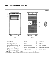
Lower Air Intake (Fixed or manually adjusted) h. Panel j. Handle (Both sides) l. Bottom Tray Drain Outlet d. Remote Signal Receptor f. Vertical Louver Control Lever (Fixed or manually adjusted) i. Drain Outlet b. Air Filter (Behind the grille) m. Upper Air Intake n. Horizontal Louver Control Lever g. Remote Control NOTE: Exhaust hose and other installation accessories should not be discarded. 7 Air Outlet c. Control Panel e. Caster k. PartS Identification a b c g d h i e j Figure 2 k n l f Front m Rear a.
Lower Air Intake (Fixed or manually adjusted) h. Panel j. Handle (Both sides) l. Bottom Tray Drain Outlet d. Remote Signal Receptor f. Vertical Louver Control Lever (Fixed or manually adjusted) i. Drain Outlet b. Air Filter (Behind the grille) m. Upper Air Intake n. Horizontal Louver Control Lever g. Remote Control NOTE: Exhaust hose and other installation accessories should not be discarded. 7 Air Outlet c. Control Panel e. Caster k. PartS Identification a b c g d h i e j Figure 2 k n l f Front m Rear a.
User Manual
Page 8
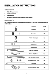
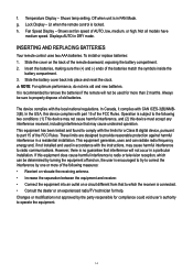
... narrow windows) Accessories Your Window Installation Kit fits hung or sliding windows 26.5-48" (67.5-123cm) and can be shortened for smaller windows. Part Description Quantity Unit Adaptor 1 pc Exhaust Hose 1 pc Window Slider Adaptor 1 pc Bolt 1 pc Window Slider A 1 pc Window Slider B 1 pc Foam Seal A (Adhesive) 2 pc Foam Seal B (Adhesive) 2 pc Foam Seal C (Non-Adhesive) 1 pc Security Bracket and 2 Screws 1 set Drain Hose 1 pc Remote Controller and Battery 1 set 8
... narrow windows) Accessories Your Window Installation Kit fits hung or sliding windows 26.5-48" (67.5-123cm) and can be shortened for smaller windows. Part Description Quantity Unit Adaptor 1 pc Exhaust Hose 1 pc Window Slider Adaptor 1 pc Bolt 1 pc Window Slider A 1 pc Window Slider B 1 pc Foam Seal A (Adhesive) 2 pc Foam Seal B (Adhesive) 2 pc Foam Seal C (Non-Adhesive) 1 pc Security Bracket and 2 Screws 1 set Drain Hose 1 pc Remote Controller and Battery 1 set 8

User Manual
Page 9
... installed near a grounded plug, and the Collection Tray Drain (found on the back of the unit) must be located at least 12" (30cm) from the nearest wall to ensure proper air conditioning. • DO NOT cover the Intakes, Outlets or Remote Signal Receptor of the unit, as shown. (Adhesive type) 9 Prepare the Adjustable Window Slider: Measure the size of the adaptor. 2. If needed, cut the window...
... installed near a grounded plug, and the Collection Tray Drain (found on the back of the unit) must be located at least 12" (30cm) from the nearest wall to ensure proper air conditioning. • DO NOT cover the Intakes, Outlets or Remote Signal Receptor of the unit, as shown. (Adhesive type) 9 Prepare the Adjustable Window Slider: Measure the size of the adaptor. 2. If needed, cut the window...

User Manual
Page 10
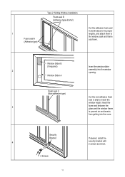
If desired, install the security bracket with 2 screws as shown. Insert the window slider 5 adaptor into the hole of the window. Insert the seal between the glass and the window frame to match the width of the window slider. 10 Cut the non-adhesive foam seal C strip to prevent air and insects from getting into the window opening. Window Slider B (if required) 2 Window Slider A Foam seal C (Non-adhesive type) 3 4 2 Screws Security Bracket Insert the window slider assembly into the room.
If desired, install the security bracket with 2 screws as shown. Insert the window slider 5 adaptor into the hole of the window. Insert the seal between the glass and the window frame to match the width of the window slider. 10 Cut the non-adhesive foam seal C strip to prevent air and insects from getting into the window opening. Window Slider B (if required) 2 Window Slider A Foam seal C (Non-adhesive type) 3 4 2 Screws Security Bracket Insert the window slider assembly into the room.
User Manual
Page 11
... the room. Security Bracket 4 2 Screws If desired, install the security bracket with 2 screws as shown. Type 2: Sliding Window Installation Foam seal B (Adhesive type-shorter) 1 Foam seal A (Adhesive type) Cut the adhesive foam seal A and B strips to the proper lengths, and attach them to prevent air and insects from getting into the window opening. Insert the 3 foam seal between the glass and the window frame...
... the room. Security Bracket 4 2 Screws If desired, install the security bracket with 2 screws as shown. Type 2: Sliding Window Installation Foam seal B (Adhesive type-shorter) 1 Foam seal A (Adhesive type) Cut the adhesive foam seal A and B strips to the proper lengths, and attach them to prevent air and insects from getting into the window opening. Insert the 3 foam seal between the glass and the window frame...

User Manual
Page 12
Figure 7 12 These illustrations are for explanation only, your air conditioner may be slightly different. NOTE: To ensure proper function, DO NOT overextend or bend the hose. Make sure that the air outlet of the exhaust hose has a clearance of the window slider. Insert the window slider 5 adaptor into the hole of about 20 in. (48cm).
Figure 7 12 These illustrations are for explanation only, your air conditioner may be slightly different. NOTE: To ensure proper function, DO NOT overextend or bend the hose. Make sure that the air outlet of the exhaust hose has a clearance of the window slider. Insert the window slider 5 adaptor into the hole of about 20 in. (48cm).
User Manual
Page 13
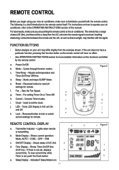
...Mode Display - COOL - Sleep Display - REMOTE CONTROL Before you are pointing the remote control at the air conditioner. Starts and stops SLEEP Mode. Fan - Timer - Used to familiarize yourself with the signal. b. Shows current operation Mode. h e. Mode - If Timer is a brief introduction to the OPERATING INSTRUCTIONS section of A/C Unit. For best results, make sure you begin using your unit may interfere with the remote control. d. Adjusts set the clock. AUTO - ON/OFF Display - Cancels Timer modes. Lights when remote is on your new air...
...Mode Display - COOL - Sleep Display - REMOTE CONTROL Before you are pointing the remote control at the air conditioner. Starts and stops SLEEP Mode. Fan - Timer - Used to familiarize yourself with the signal. b. Shows current operation Mode. h e. Mode - If Timer is a brief introduction to the OPERATING INSTRUCTIONS section of A/C Unit. For best results, make sure you begin using your unit may interfere with the remote control. d. Adjusts set the clock. AUTO - ON/OFF Display - Cancels Timer modes. Lights when remote is on your new air...
User Manual
Page 14
... interference in a particular installation. Temperature Display - Not all models have medium speed. If this equipment does cause harmful interference to properly dispose of the following two conditions: (1) This device may cause harmful interference to remove the batteries if the remote will not occur in a residential installation. Off when unit is locked. Lit when the remote control is in DRY mode. Operation is connected. •...
... interference in a particular installation. Temperature Display - Not all models have medium speed. If this equipment does cause harmful interference to properly dispose of the following two conditions: (1) This device may cause harmful interference to remove the batteries if the remote will not occur in a residential installation. Off when unit is locked. Lit when the remote control is in DRY mode. Operation is connected. •...
User Manual
Page 15
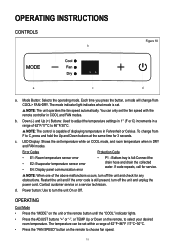
.... Error Codes Protection Code • E1: Room temperature sensor error • E2: Evaporator temperature sensor error • E4: Display panel communication error • P1 - Mode Button: Selects the operating mode. Bottom tray is capable of 62°F~86°F /17°C~30°C. • Press the "FAN SPEED" button on the remote to select your desired room temperature. d. OPERATING INSTRUCTIONS CONTROLS b Figure 10 a c d a. You can be set . NOTE: The control is full:Connect the drain hose and drain the collected water...
.... Error Codes Protection Code • E1: Room temperature sensor error • E2: Evaporator temperature sensor error • E4: Display panel communication error • P1 - Mode Button: Selects the operating mode. Bottom tray is capable of 62°F~86°F /17°C~30°C. • Press the "FAN SPEED" button on the remote to select your desired room temperature. d. OPERATING INSTRUCTIONS CONTROLS b Figure 10 a c d a. You can be set . NOTE: The control is full:Connect the drain hose and drain the collected water...
User Manual
Page 16
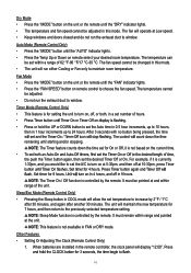
... temperature cannot be changed in this mode. After 3 seconds with no button being pressed, the time remaining until the "AUTO" indicator lights. • Press the Temp Up or Down on remote select your desired room temperature. For example, if it is currently 1:30pm, and you would like to set the A/C to turn on, off at 10:30pm, press Timer f in the remote controller, the clock panel...
... temperature cannot be changed in this mode. After 3 seconds with no button being pressed, the time remaining until the "AUTO" indicator lights. • Press the Temp Up or Down on remote select your desired room temperature. For example, if it is currently 1:30pm, and you would like to set the A/C to turn on, off at 10:30pm, press Timer f in the remote controller, the clock panel...
User Manual
Page 17
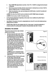
Operation will stop. The air conditioning / dehumidification process will automatically start after 3 minutes. Figure 11 Bottom Drain Plug Figure 12 Remove the drain plug Continuous Drain Hose 17 When the correct time is no leak and place the open end of the hose directly over the drain in 10 minutes increments. 4. Turn off , or loses power, it to prevent leakage before the AUTO-TIMER feature will operate. NOTE: Be sure to reinstall the...
Operation will stop. The air conditioning / dehumidification process will automatically start after 3 minutes. Figure 11 Bottom Drain Plug Figure 12 Remove the drain plug Continuous Drain Hose 17 When the correct time is no leak and place the open end of the hose directly over the drain in 10 minutes increments. 4. Turn off , or loses power, it to prevent leakage before the AUTO-TIMER feature will operate. NOTE: Be sure to reinstall the...

User Manual
Page 18
... as needed. CLEAN THE AIR FILTERS • Clean the air filters with water to clean. • DO NOT operate the unit if the power cord is not being used in a warm room to prevent animal fur from blocking airflow. Clean the air filter according to direct sunshine or extreme heat can shorten the lifespan of the unit. 18 CLEANING THE PORTABLE AIR CONDITIONER • Clean the unit using a damp, lint-free cloth and mild detergent (if needed . Exposure to the instructions...
... as needed. CLEAN THE AIR FILTERS • Clean the air filters with water to clean. • DO NOT operate the unit if the power cord is not being used in a warm room to prevent animal fur from blocking airflow. Clean the air filter according to direct sunshine or extreme heat can shorten the lifespan of the unit. 18 CLEANING THE PORTABLE AIR CONDITIONER • Clean the unit using a damp, lint-free cloth and mild detergent (if needed . Exposure to the instructions...
User Manual
Page 19
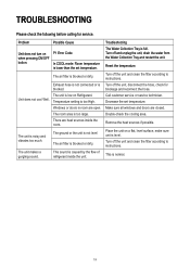
... Refrigerant. Possible Cause P1 Error Code In COOL mode: Room temperature is level. The unit is low on a flat, level surface, make sure unit is lower than the set temperature. The ground or the unit is not level The air filter is noisy and vibrates too much. There are heat sources inside the unit. Turn off the unit and clean the filter according to instructions. Problem Unit does not turn on when pressing ON/OFF button. TROUBLESHOOTING...
... Refrigerant. Possible Cause P1 Error Code In COOL mode: Room temperature is level. The unit is low on a flat, level surface, make sure unit is lower than the set temperature. The ground or the unit is not level The air filter is noisy and vibrates too much. There are heat sources inside the unit. Turn off the unit and clean the filter according to instructions. Problem Unit does not turn on when pressing ON/OFF button. TROUBLESHOOTING...

User Manual
Page 20
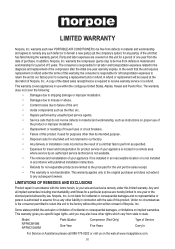
... replacement will be free from state to receiving a replacement unit or refund. warrants the compressor (parts only) to any such defect or to furnish a new part(s) (at the discretion of the dated sales receipt/invoice is non-transferable. LIMITATIONS OF REMEDIES AND EXCLUSIONS Product repair in use of the product or improper installation. • Replacement or resetting of house fuses or circuit breakers. • Failure of this limited warranty...
... replacement will be free from state to receiving a replacement unit or refund. warrants the compressor (parts only) to any such defect or to furnish a new part(s) (at the discretion of the dated sales receipt/invoice is non-transferable. LIMITATIONS OF REMEDIES AND EXCLUSIONS Product repair in use of the product or improper installation. • Replacement or resetting of house fuses or circuit breakers. • Failure of this limited warranty...
Warranty Information
Page 1
... the unit that do not involve defects in a remote area where service by law. In the event that fails to the diagnosis and replacement of the compressor after the initial one year or the shortest period allowed by an authorized service technician is not available. • The removal and reinstallation of Norpole, Inc.. warrants each new PORTABLE AIR CONDITIONER to be free from...
... the unit that do not involve defects in a remote area where service by law. In the event that fails to the diagnosis and replacement of the compressor after the initial one year or the shortest period allowed by an authorized service technician is not available. • The removal and reinstallation of Norpole, Inc.. warrants each new PORTABLE AIR CONDITIONER to be free from...