User Manual (English)
Page 2
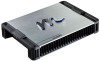
... reference. We suggest you may need service or replacement due to document the information below, which will provide you with many years of theft or if service is needed. You now own a MACROM M2A-series amplifier, the product of innovation and the highest quality control standards. Please retain this manual and your information on the following lines to refer to in the...
... reference. We suggest you may need service or replacement due to document the information below, which will provide you with many years of theft or if service is needed. You now own a MACROM M2A-series amplifier, the product of innovation and the highest quality control standards. Please retain this manual and your information on the following lines to refer to in the...
User Manual (English)
Page 5
... RCA outputs, so use with source units that have high pass filter, the frequency range is 6V to check wire for low pass, flat or high pass. Be sure to 200mV. Warning: Always protect this terminal through a FUSE or CIRCUIT BREAKER to the bare metal. RCA input jacks These RCA input jacks are for use of an isolated audio system battery. High level inputs The high level inputs are for use this cable directly to the frame of the battery terminal connection. 3.Remote Turn...
... RCA outputs, so use with source units that have high pass filter, the frequency range is 6V to check wire for low pass, flat or high pass. Be sure to 200mV. Warning: Always protect this terminal through a FUSE or CIRCUIT BREAKER to the bare metal. RCA input jacks These RCA input jacks are for use of an isolated audio system battery. High level inputs The high level inputs are for use this cable directly to the frame of the battery terminal connection. 3.Remote Turn...
User Manual (English)
Page 6
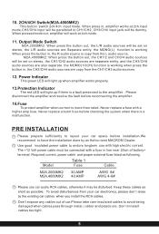
Output Mode Switch M2A.2000MK2: When press the button out, the L/R audio sources will be connected with a fuse in , the CH2/CH4 audio sources are also separate. Never replace a burnt fuse before reconnecting the amplifier. 14.Fuse To protect amplifier when current is more than rated. Model Table 1 Fuse Cable M2A.2000MK2 M2A.4000MK2 30 AMP 40 AMP AWG 8# AWG 4-8# Please use with a higher amp fuse. Don't expose any cables out of battery+ terminal. Never replace a fuse with high electric current. The...
Output Mode Switch M2A.2000MK2: When press the button out, the L/R audio sources will be connected with a fuse in , the CH2/CH4 audio sources are also separate. Never replace a burnt fuse before reconnecting the amplifier. 14.Fuse To protect amplifier when current is more than rated. Model Table 1 Fuse Cable M2A.2000MK2 M2A.4000MK2 30 AMP 40 AMP AWG 8# AWG 4-8# Please use with a higher amp fuse. Don't expose any cables out of battery+ terminal. Never replace a fuse with high electric current. The...
User Manual (English)
Page 7
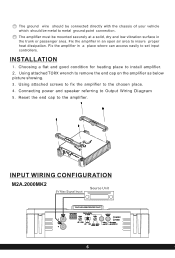
... amplifier. 11\ INPUT WIRING CONFIGURATION M2A.2000MK2 5V Max Signal Input Source Unit 0 0 L 0 ne®0.1CISID ',OF, nn OV I WE T 0. • ev*' olv I I ENT i 1 1 °POWER 0 ''' r H. Reset the end cap to set input controllers. INSTALLATION 1. Connecting power and speaker referring to remove the end cap on the amplifier as below picture showing. 3. Using attached TORX wrench to Output Wiring Diagram 5. Using attached screws to fix the amplifier to insure proper heat dissipation. The ground wire should be connected directly...
... amplifier. 11\ INPUT WIRING CONFIGURATION M2A.2000MK2 5V Max Signal Input Source Unit 0 0 L 0 ne®0.1CISID ',OF, nn OV I WE T 0. • ev*' olv I I ENT i 1 1 °POWER 0 ''' r H. Reset the end cap to set input controllers. INSTALLATION 1. Connecting power and speaker referring to remove the end cap on the amplifier as below picture showing. 3. Using attached TORX wrench to Output Wiring Diagram 5. Using attached screws to fix the amplifier to insure proper heat dissipation. The ground wire should be connected directly...
User Manual (English)
Page 9
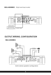
F,I .,H.'.....r c,. . ( S,---, 6.M7MI ERIMIMR UM. eh B Di - R W 0 8 0 R 8 FUSE + en REM -4-, LI 0 ' 10 0 1,%,1 10 0 ri ICI 0 4ohm stereo speaker configuration V ..".. M2A.4000MK2 (High level input mode) Source Unit I ,cH 1 LPF HPF 30. 600. 0 speaker signal OUTPUT WIRING CONFIGURATION M2A.2000MK2 FUSEH +132:1 REM 64;g16WINE 51 3 - tHO . ... "11v, LEVEL cH HP, CN1 CHI 0 0 krtr-' t *:: ' tItfr PU OUTPUT 0 PROTECT 0 POWER H221 IoWOXON.
F,I .,H.'.....r c,. . ( S,---, 6.M7MI ERIMIMR UM. eh B Di - R W 0 8 0 R 8 FUSE + en REM -4-, LI 0 ' 10 0 1,%,1 10 0 ri ICI 0 4ohm stereo speaker configuration V ..".. M2A.4000MK2 (High level input mode) Source Unit I ,cH 1 LPF HPF 30. 600. 0 speaker signal OUTPUT WIRING CONFIGURATION M2A.2000MK2 FUSEH +132:1 REM 64;g16WINE 51 3 - tHO . ... "11v, LEVEL cH HP, CN1 CHI 0 0 krtr-' t *:: ' tItfr PU OUTPUT 0 PROTECT 0 POWER H221 IoWOXON.
User Manual (English)
Page 10
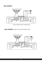
REM EW2,1 11 2,6M:114:B.1 I -) 'g , I!)() I GOB OM 0 8 0 " 8 FUR +dn RE., -4-. l:,,1 Igl I:11 (%) © I:J c) IJ -i c 4ohm bridged woofer configuration M2A.2000MK2 (High level input & bridged mode) Bridged 4 ohm woofer FUSE ON/OFF control signal I GOB DEED • ,E85 o o o o 0 i lF=us11=1 I +061 REM 4- M2A.2000MK2 Bridged 4 ohm woofer FUSEI-
REM EW2,1 11 2,6M:114:B.1 I -) 'g , I!)() I GOB OM 0 8 0 " 8 FUR +dn RE., -4-. l:,,1 Igl I:11 (%) © I:J c) IJ -i c 4ohm bridged woofer configuration M2A.2000MK2 (High level input & bridged mode) Bridged 4 ohm woofer FUSE ON/OFF control signal I GOB DEED • ,E85 o o o o 0 i lF=us11=1 I +061 REM 4- M2A.2000MK2 Bridged 4 ohm woofer FUSEI-
User Manual (English)
Page 12
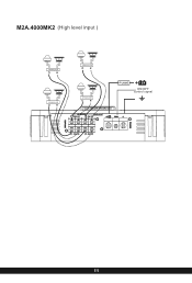
i CH3 + CHO Q I +e' REM 4.- 0 • . tO 0 0 c O0 O 0 c.v.° 0 CH .. ....... .. ..** 11 M2A.4000MK2 (High level input ) CROSSOV R CROSSOV R CROSSOV R CROSSOV R FUSE ON/OFF control signal . .* an ilitio.
i CH3 + CHO Q I +e' REM 4.- 0 • . tO 0 0 c O0 O 0 c.v.° 0 CH .. ....... .. ..** 11 M2A.4000MK2 (High level input ) CROSSOV R CROSSOV R CROSSOV R CROSSOV R FUSE ON/OFF control signal . .* an ilitio.
User Manual (English)
Page 13
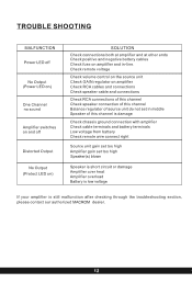
...Check remote wire connect right Source unit gain set too high Amplifier gain set in -line. TROUBLE SHOOTING MALFUNCTION Power LED off No Output (Power LED on) One Channel no sound Amplifier switches on and off Distorted Output No Output (Protect LED on) SOLUTION Check connections both at amplifier and at other ends Check positive and negative battery cables Check fuse on amplifier Check RCA cables and connections Check speaker cable and connections Check RCA connections of this channel Check speaker connection of source unit do not set too high Speaker(s) blown Speaker is short circuit...
...Check remote wire connect right Source unit gain set too high Amplifier gain set in -line. TROUBLE SHOOTING MALFUNCTION Power LED off No Output (Power LED on) One Channel no sound Amplifier switches on and off Distorted Output No Output (Protect LED on) SOLUTION Check connections both at amplifier and at other ends Check positive and negative battery cables Check fuse on amplifier Check RCA cables and connections Check speaker cable and connections Check RCA connections of this channel Check speaker connection of source unit do not set too high Speaker(s) blown Speaker is short circuit...

User Manual (English)
Page 14
SPECIFICATION Model RMS @ 4OHM (Power supplier 14.4V) RMS @ 2OHM (Power supplier 14.4V) RMS @ 4Ohm Bridged (Power supplier 14AV) Input Level High level input Channel InputAdjust CH1/CH2 Filter mode CH3/CH4 Filter mode CHL/R Filter mode CH1/CH2 HPF CH3/CH4 HPF CH3/CH4 LPF CHL/R HPF CHL/R LPF Frequency Response THD at 4Ohm load 30% Rated Power S/N Ratio Channel seperation Minimum Load Overload protect system Overheat protect system Components & PCB HI-END design DimensionsLxWxHmm...
SPECIFICATION Model RMS @ 4OHM (Power supplier 14.4V) RMS @ 2OHM (Power supplier 14.4V) RMS @ 4Ohm Bridged (Power supplier 14AV) Input Level High level input Channel InputAdjust CH1/CH2 Filter mode CH3/CH4 Filter mode CHL/R Filter mode CH1/CH2 HPF CH3/CH4 HPF CH3/CH4 LPF CHL/R HPF CHL/R LPF Frequency Response THD at 4Ohm load 30% Rated Power S/N Ratio Channel seperation Minimum Load Overload protect system Overheat protect system Components & PCB HI-END design DimensionsLxWxHmm...
