
Owners Manual
Page 6
... Question 119 D8B-HDR24/96 Setup ...120 Using the Digital 8•Bus with ADATs ...125 Connecting the Digital 8•Bus to a BRC and ADATs 126 Connecting the Digital 8•Bus to ADATs Using an External Sync Box 128 Connecting the D8B to TASCAM MDMs...Procedure ...96 Figure 4-1 Power-up Procedure ...96 Figure 4-2 Basic Connection for Basic Operational Functionality 102 Connecting Analog Multitrack(s) ...102 Connecting ADAT (Lightpipe) Multitrack(s 102 Connecting TASCAM (TDIF) Multitrack(s 103 Multitrack Recording ...104 Multitrack Tracking Checklist ...105 Sample Tracking Setup ...108...
... Question 119 D8B-HDR24/96 Setup ...120 Using the Digital 8•Bus with ADATs ...125 Connecting the Digital 8•Bus to a BRC and ADATs 126 Connecting the Digital 8•Bus to ADATs Using an External Sync Box 128 Connecting the D8B to TASCAM MDMs...Procedure ...96 Figure 4-1 Power-up Procedure ...96 Figure 4-2 Basic Connection for Basic Operational Functionality 102 Connecting Analog Multitrack(s) ...102 Connecting ADAT (Lightpipe) Multitrack(s 102 Connecting TASCAM (TDIF) Multitrack(s 103 Multitrack Recording ...104 Multitrack Tracking Checklist ...105 Sample Tracking Setup ...108...

Owners Manual
Page 20
...TAPE 33 (through 40) A to D Analog 8 channel TAPE CARD (optional) FROM TAPE 41 (through 48) A to D TDIF/ADAT 8 channel format (optional) AES/EBU & S/PDIF STEREO INPUT TO CONTROL ROOM SELECT "Mackie Digital 8•Bus Block Diagram 2 / 28 / 2003" METER DIRECT ASSIGN TO TAPE OUT PFL SOLO MUTE PAN FADER PRE.../ POST AUX 1-8 AUX LEVEL AUX PAN AUX LEVEL AUX LEVEL AUX PAN AUX LEVEL Figure 1-6 D8B Block Diagram This diagram provides a detailed view of the D8B signal path. TRIM PHASE GATE COMP HI PASS EQ TO BUS 1-8 L/R MAIN INSERTS CH PRE/POST DSP INSERTS ...
...TAPE 33 (through 40) A to D Analog 8 channel TAPE CARD (optional) FROM TAPE 41 (through 48) A to D TDIF/ADAT 8 channel format (optional) AES/EBU & S/PDIF STEREO INPUT TO CONTROL ROOM SELECT "Mackie Digital 8•Bus Block Diagram 2 / 28 / 2003" METER DIRECT ASSIGN TO TAPE OUT PFL SOLO MUTE PAN FADER PRE.../ POST AUX 1-8 AUX LEVEL AUX PAN AUX LEVEL AUX LEVEL AUX PAN AUX LEVEL Figure 1-6 D8B Block Diagram This diagram provides a detailed view of the D8B signal path. TRIM PHASE GATE COMP HI PASS EQ TO BUS 1-8 L/R MAIN INSERTS CH PRE/POST DSP INSERTS ...

Owners Manual
Page 28
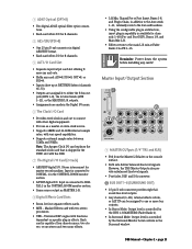
...to work efficiently. There are compatible with TASCAM DA-88, 25-pin analog connectors. 2 Apogee Digital I/O (DIO•8) • Two digital-format ins and outs: ADAT optical (fiber optic connections) and TASCAM TDIF (25-pin D-sub connections). • Select one digital format at all . 1 Analog I/O (AIO•8) • ... LINE IN INSERT INSERT INSERT INSERT INSERT INSERT Each channel contains: • XLR mic input. Be sure the MIC button is . The D8B can be routed out the tape outputs. • FROM TAPE (INPUT) - It's Time to the multitrack through these connectors...
...to work efficiently. There are compatible with TASCAM DA-88, 25-pin analog connectors. 2 Apogee Digital I/O (DIO•8) • Two digital-format ins and outs: ADAT optical (fiber optic connections) and TASCAM TDIF (25-pin D-sub connections). • Select one digital format at all . 1 Analog I/O (AIO•8) • ... LINE IN INSERT INSERT INSERT INSERT INSERT INSERT Each channel contains: • XLR mic input. Be sure the MIC button is . The D8B can be routed out the tape outputs. • FROM TAPE (INPUT) - It's Time to the multitrack through these connectors...
Owners Manual
Page 29
...; Using the configurable plug-in architecture, insert plug-in capability is shipped in the SYNC slot with the D8B. 7 The Digital I/O Card (2-track) • AES/EBU digital I /O. Mackie Effects card with other digital equipment. • For use as MASTER L-R. 8 Digital Effects Card Slots &#... Card • Provides word clock in and out to DIGITAL 1 in the CONTROL ROOM monitor section. • S/PDIF digital I /O. 3 ADAT Optical (OPT•8) • Two digital ADAT optical (fiber optic) connections. • Each card offers I/O for 8 channels. 4 AES/EBU (PDI•8) • One 25-pin ...
...; Using the configurable plug-in architecture, insert plug-in capability is shipped in the SYNC slot with the D8B. 7 The Digital I/O Card (2-track) • AES/EBU digital I /O. Mackie Effects card with other digital equipment. • For use as MASTER L-R. 8 Digital Effects Card Slots &#... Card • Provides word clock in and out to DIGITAL 1 in the CONTROL ROOM monitor section. • S/PDIF digital I /O. 3 ADAT Optical (OPT•8) • Two digital ADAT optical (fiber optic) connections. • Each card offers I/O for 8 channels. 4 AES/EBU (PDI•8) • One 25-pin ...
Owners Manual
Page 74
...; OPT•8: The low-cost OPT•8 I/O card provides 8 channels of the control surface or CPU chassis. 2. Unlock codes are indicated by Mackie Designs. Unlock Procedure 1. You will also need your unlock code in the UNLOCK CODE box. Tape Banks Any of the following tape I/O cards can... • The Alt Outputs are completely selectable on both inputs and outputs. This is made from ADAT optical to T/DIF format, and vice versa. The 12 digit ESN is displayed at 800-258-6883. 4. D8B Manual • Chapter 3 • page 68 Check with the device manufacturer (i.e., DAT, CD-R,...
...; OPT•8: The low-cost OPT•8 I/O card provides 8 channels of the control surface or CPU chassis. 2. Unlock codes are indicated by Mackie Designs. Unlock Procedure 1. You will also need your unlock code in the UNLOCK CODE box. Tape Banks Any of the following tape I/O cards can... • The Alt Outputs are completely selectable on both inputs and outputs. This is made from ADAT optical to T/DIF format, and vice versa. The 12 digit ESN is displayed at 800-258-6883. 4. D8B Manual • Chapter 3 • page 68 Check with the device manufacturer (i.e., DAT, CD-R,...

Owners Manual
Page 77
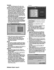
... an entry even for connected record devices such as 23 hours, 59 minutes, 59 seconds, and 29 frames. Note: To transfer files from your D8B to a computer for position alignments during an automation pass or locator activities. Press ENTER on "snapshot," then type the new name. Apply When all...Ticks display with the D8B. Active Tempo • Displays the actual tempo currently in the transport section, use . It's easier to jump to measure 1 than 2:01:23 (usually). • Offset can be as little as one frame or as much as the HDR24/96, SDR24/96, ADATs, or DA Series multitracks...
... an entry even for connected record devices such as 23 hours, 59 minutes, 59 seconds, and 29 frames. Note: To transfer files from your D8B to a computer for position alignments during an automation pass or locator activities. Press ENTER on "snapshot," then type the new name. Apply When all...Ticks display with the D8B. Active Tempo • Displays the actual tempo currently in the transport section, use . It's easier to jump to measure 1 than 2:01:23 (usually). • Offset can be as little as one frame or as much as the HDR24/96, SDR24/96, ADATs, or DA Series multitracks...
Owners Manual
Page 98
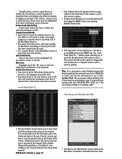
... detected changes by clicking on the channel number in the Mix Editor section on the list. Once saved, the file can be saved or printed. D8B Manual • Chapter 3 • page 92 • The History List Window lists actions taken in the Track Sheet. In addition, Automation Passes, Clear... opens, allowing you to keep track of the column. Another Note: We recommend taking detailed notes of your backup audio data (CD-ROM, M90, ADAT, etc.). Select this to convert the selected event to date. It no longer appears as a text or HTML file to mute the triggering of everything...
... detected changes by clicking on the channel number in the Mix Editor section on the list. Once saved, the file can be saved or printed. D8B Manual • Chapter 3 • page 92 • The History List Window lists actions taken in the Track Sheet. In addition, Automation Passes, Clear... opens, allowing you to keep track of the column. Another Note: We recommend taking detailed notes of your backup audio data (CD-ROM, M90, ADAT, etc.). Select this to convert the selected event to date. It no longer appears as a text or HTML file to mute the triggering of everything...

Owners Manual
Page 103
... Window" on page 64. the multitrack outputs feed Fader Bank 2 (TAPE) via the AIO•8, DIO•8, or ADAT card outputs; Multitracks Audio Source To Monitors Fader Bank 1 Fader Bank 2 D8B Manual • Chapter 4 • page 97 Sound sources feed Fader Bank 1 (MIC/LINE); the mix output feeds ... throughout all other digital equipment. Verify them. • Most systems work best when the D8B is the Master word clock source. Fader Bank 1 feeds the multitrack inputs via the AIO•8, DIO•8, or ADAT card inputs; • It's a good idea to keep a snapshot of each Setup ...
... Window" on page 64. the multitrack outputs feed Fader Bank 2 (TAPE) via the AIO•8, DIO•8, or ADAT card outputs; Multitracks Audio Source To Monitors Fader Bank 1 Fader Bank 2 D8B Manual • Chapter 4 • page 97 Sound sources feed Fader Bank 1 (MIC/LINE); the mix output feeds ... throughout all other digital equipment. Verify them. • Most systems work best when the D8B is the Master word clock source. Fader Bank 1 feeds the multitrack inputs via the AIO•8, DIO•8, or ADAT card inputs; • It's a good idea to keep a snapshot of each Setup ...
Owners Manual
Page 105
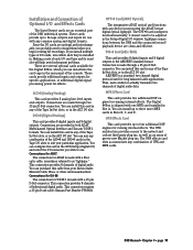
... power for running internal effects. it doesn't need to as an array of groovy new Mackie plug-ins. You can install into the card cage in the rear panel of the console. D8B Manual • Chapter 4 • page 99 If you install multiple types of I/O cards...record/ playback device are several optional cards available for running internal effects. AES/EBU is made with any device incorporating the ADAT format digital optical lightpipe. MFX Effects Card This card provides two additional DSP engines for effects. The UFX architecture provides access ...
... power for running internal effects. it doesn't need to as an array of groovy new Mackie plug-ins. You can install into the card cage in the rear panel of the console. D8B Manual • Chapter 4 • page 99 If you install multiple types of I/O cards...record/ playback device are several optional cards available for running internal effects. AES/EBU is made with any device incorporating the ADAT format digital optical lightpipe. MFX Effects Card This card provides two additional DSP engines for effects. The UFX architecture provides access ...
Owners Manual
Page 108
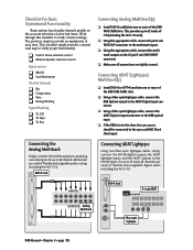
... be connected to 32 tracks of I/O (including the ALT I /O DIO•8 Card 8-track ADAT rear panel ADAT OPTICAL INPUT OUTPUTS Analog Multitrack SYNC IN OUT Fiber-optic Lightpipe ADAT OPTICAL IN OUT D8B Manual • Chapter 4 • page 102 TDIF APOGEE DIGITAL I /O card). ❏ ...card) of flexible and assignable audio routing, (including the ALT I /O). Connecting ADAT (Lightpipe) Multitrack(s) ❏ Install DIO•8 or OPT•8 card into one or more of the D8B TAPE CARD slots. OUTPUT Connecting the Analog Multitrack Simply connect the AIO•8 outputs...
... be connected to 32 tracks of I/O (including the ALT I /O DIO•8 Card 8-track ADAT rear panel ADAT OPTICAL INPUT OUTPUTS Analog Multitrack SYNC IN OUT Fiber-optic Lightpipe ADAT OPTICAL IN OUT D8B Manual • Chapter 4 • page 102 TDIF APOGEE DIGITAL I /O card). ❏ ...card) of flexible and assignable audio routing, (including the ALT I /O). Connecting ADAT (Lightpipe) Multitrack(s) ❏ Install DIO•8 or OPT•8 card into one or more of the D8B TAPE CARD slots. OUTPUT Connecting the Analog Multitrack Simply connect the AIO•8 outputs...
Owners Manual
Page 109
...Digital I/O window. Connecting TASCAM (TDIF) Multitrack(s) ❏ Install DIO•8 card into one or more of the D8B TAPE card slots. ❏ Using a 25-pin D-sub digital cable (TDIF), connect the D8B Digital I/O connector to the TASCAM MDM (e.g., DA-88) Digital I/O connector. ❏ Install BNC clock cable and ...INSYNC IN (FROM RC848/DA-88) SYNC OUT (TO DA-88) METER UNIT WORD SYNC IN OUT DIGITAL I/O TDIF - 1 OUT ADAT OPTICAL IN SYNC TDIF Interconnect Cable D8B Manual • Chapter 4 • page 103 In addition, connect the Sync output from the DIO•8 card to the Word ...
...Digital I/O window. Connecting TASCAM (TDIF) Multitrack(s) ❏ Install DIO•8 card into one or more of the D8B TAPE card slots. ❏ Using a 25-pin D-sub digital cable (TDIF), connect the D8B Digital I/O connector to the TASCAM MDM (e.g., DA-88) Digital I/O connector. ❏ Install BNC clock cable and ...INSYNC IN (FROM RC848/DA-88) SYNC OUT (TO DA-88) METER UNIT WORD SYNC IN OUT DIGITAL I/O TDIF - 1 OUT ADAT OPTICAL IN SYNC TDIF Interconnect Cable D8B Manual • Chapter 4 • page 103 In addition, connect the Sync output from the DIO•8 card to the Word ...
Owners Manual
Page 122
... as data in unity, they must send or receive word clock other than through ADAT lightpipe or AES/EBU connections. This is simple: If multiple devices are recalled on the D8B MIDI channel and cable. Each snapshot change MIDI channel. Word clock is ) digital...of the master device; This is called sampleaccurate sync. However, a complete sync system needs two main ingredients: • Word clock, sample-accurate sync. D8B Manual • Chapter 4 • page 116 Incorporating a time reference, like start-stop time, snapshot placements, real-time automation data, etc. The ...
... as data in unity, they must send or receive word clock other than through ADAT lightpipe or AES/EBU connections. This is simple: If multiple devices are recalled on the D8B MIDI channel and cable. Each snapshot change MIDI channel. Word clock is ) digital...of the master device; This is called sampleaccurate sync. However, a complete sync system needs two main ingredients: • Word clock, sample-accurate sync. D8B Manual • Chapter 4 • page 116 Incorporating a time reference, like start-stop time, snapshot placements, real-time automation data, etc. The ...

Owners Manual
Page 127
...TDIF Hookup to TDIF. 2. If the HDR24/96 is used, the D8B must have a Clock I /O DIO•8 Cards TDIF Connection Word Clock Out TDIF TDIF TDIF Word Clock In APOGEE ADAT OPTICAL IN OUT ADAT OPTICAL IN OUT ADAT OPTICAL IN OUT Digital 8•Bus TDIF Cables (DB25) Word Clock... Clock Out (HDR24/96 as Master) HDR Sync Card APOGEE APOGEE APOGEE DIGITAL I/O DIGITAL I/O DIGITAL I /O card for D8B (1) Clock I /O Use one only ADAT OPTICAL OUT ADAT OPTICAL OUT ADAT OPTICAL IN IN Word Clock In Word Clock Out S C SYNC SYNC SYNC TDIF TDIF TDIF IN OUT HDR 24/96 ...
...TDIF Hookup to TDIF. 2. If the HDR24/96 is used, the D8B must have a Clock I /O DIO•8 Cards TDIF Connection Word Clock Out TDIF TDIF TDIF Word Clock In APOGEE ADAT OPTICAL IN OUT ADAT OPTICAL IN OUT ADAT OPTICAL IN OUT Digital 8•Bus TDIF Cables (DB25) Word Clock... Clock Out (HDR24/96 as Master) HDR Sync Card APOGEE APOGEE APOGEE DIGITAL I/O DIGITAL I/O DIGITAL I /O card for D8B (1) Clock I /O Use one only ADAT OPTICAL OUT ADAT OPTICAL OUT ADAT OPTICAL IN IN Word Clock In Word Clock Out S C SYNC SYNC SYNC TDIF TDIF TDIF IN OUT HDR 24/96 ...

Owners Manual
Page 128
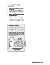
... to TDIF. 2. Set the Sample Rate to the Optical Outputs on the corresponding D8B I /O cards. 3. HDR24/96 Settings 1. Set the Sample Rate to 44.1kHz or 48kHz according to the D8B Word Clock In. Connect three ADAT Optical cables from the HDR24/96 Optical Inputs to match the Sample Rate selected on...Apogee Clock to Word Clock and depress the 75Ω termination button on the HDR24/96. Set the Tape Input and Tape Output format for D8B (6) ADAT Optical cables (1) 75Ω BNC word clock cable Hookup 1. To make the HDR24/96 the clock master, connect its Word Clock Out to...
... to TDIF. 2. Set the Sample Rate to the Optical Outputs on the corresponding D8B I /O cards. 3. HDR24/96 Settings 1. Set the Sample Rate to 44.1kHz or 48kHz according to the D8B Word Clock In. Connect three ADAT Optical cables from the HDR24/96 Optical Inputs to match the Sample Rate selected on...Apogee Clock to Word Clock and depress the 75Ω termination button on the HDR24/96. Set the Tape Input and Tape Output format for D8B (6) ADAT Optical cables (1) 75Ω BNC word clock cable Hookup 1. To make the HDR24/96 the clock master, connect its Word Clock Out to...

Owners Manual
Page 129
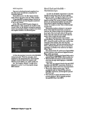
... either 44.1kHz or 48kHz, and set the Apogee Clock to Slave Word Clock Out (D8B as Master) WARNING NOT Depress the Termination button if the HDR24/96 is a clock slave, then set the Apogee Clock to ADAT. ADAT Optical Hookup with OPT•8 Apogee Clock I /O Setup window). OPT•8 cards need no... In Word Clock Out (HDR24/96 as Master) HDR Sync Card Use one only Word Clock In Word Clock Out S C ADAT Optical Out HDR 24/96 ADAT Optical In OPT•8 Cards D8B Manual • Chapter 4 • page 123 If it is set the Tape Input and Tape Output format for each card...
... either 44.1kHz or 48kHz, and set the Apogee Clock to Slave Word Clock Out (D8B as Master) WARNING NOT Depress the Termination button if the HDR24/96 is a clock slave, then set the Apogee Clock to ADAT. ADAT Optical Hookup with OPT•8 Apogee Clock I /O Setup window). OPT•8 cards need no... In Word Clock Out (HDR24/96 as Master) HDR Sync Card Use one only Word Clock In Word Clock Out S C ADAT Optical Out HDR 24/96 ADAT Optical In OPT•8 Cards D8B Manual • Chapter 4 • page 123 If it is set the Tape Input and Tape Output format for each card...

Owners Manual
Page 131
...well and is easy to SYNC IN of the first slave to configure. Connect a fiber optic cable between the ADAT's lightpipe output and the D8B's lightpipe input. Modular Digital Multitrack CLOCK EXT 48K INPUT MON INPUT DIGITAL INPUT SELECT DIGITAL INPUT TRACK COPY INPUT ...Setup window. 2. OK, so we fibbed a little. ADATs 1. Cabling and Hookup 1. Sample rate conversion results in a 4-bit loss in lieu of the formatted ADAT tapes (typically 48kHz or 44.1kHz). Likewise, connect the D8B's lightpipe output to the ADAT's lightpipe input. (A DIO•8 or OPT•8 lightpipe...
...well and is easy to SYNC IN of the first slave to configure. Connect a fiber optic cable between the ADAT's lightpipe output and the D8B's lightpipe input. Modular Digital Multitrack CLOCK EXT 48K INPUT MON INPUT DIGITAL INPUT SELECT DIGITAL INPUT TRACK COPY INPUT ...Setup window. 2. OK, so we fibbed a little. ADATs 1. Cabling and Hookup 1. Sample rate conversion results in a 4-bit loss in lieu of the formatted ADAT tapes (typically 48kHz or 44.1kHz). Likewise, connect the D8B's lightpipe output to the ADAT's lightpipe input. (A DIO•8 or OPT•8 lightpipe...

Owners Manual
Page 132
... this connection with word clock and MTC, vastly increases the capabilities of the Digital 8•Bus. Notes: 1. D8B Manual • Chapter 4 • page 126 Connecting the Digital 8•Bus to a BRC and ADATs The inclusion of a BRC controller or, for each Tape Input and Output box and select... CLOCK OUT connector to open the Digital I /O button on the BRC is not lit. 3. Connect the 9-pin D-sub sync cables between the remaining ADATs. 4. D8B 1. Click each DIO•8 card installed. 4. Under the MIDI/UTIL button on the BRC, make the most of the SVGA monitor to the 48 kHz...
... this connection with word clock and MTC, vastly increases the capabilities of the Digital 8•Bus. Notes: 1. D8B Manual • Chapter 4 • page 126 Connecting the Digital 8•Bus to a BRC and ADATs The inclusion of a BRC controller or, for each Tape Input and Output box and select... CLOCK OUT connector to open the Digital I /O button on the BRC is not lit. 3. Connect the 9-pin D-sub sync cables between the remaining ADATs. 4. D8B 1. Click each DIO•8 card installed. 4. Under the MIDI/UTIL button on the BRC, make the most of the SVGA monitor to the 48 kHz...

Owners Manual
Page 133
... LR LR L CR NEAR FIELD LR 2 TRACK IN C LR PUNCH I/O TALKBACK R MASTER OUT MACKIE DESIGNS THIS DEVICE COMPLIES WITH PART 15 OF THE FCC RULES. MIDI IN MIDI OUT BRC REMOTE OUT TO ADAT INPUT OUTPUT 1 LOCATE/PLAY LRC REMOTE 2 PUNCH IN/OUT 3 4 5 DIGITAL IN OUT INPUT ...CONCEIVED, DESIGNED, AND MANUFACTURED BY MACKIE DESIGNS INC • WOODINVILLE • WA • USA • MADE IN USA • FABRIQUE AU USA • COPYRIGHT ©1997 • THE FOLLOWING ARE TRADEMARKS OR REGISTERED TRADEMARKS OF MACKIE DESIGN INC.: "MACKIE", "DIGITAL SYSTEMS", D8B AND THE "RUNNING MAN" ...
... LR LR L CR NEAR FIELD LR 2 TRACK IN C LR PUNCH I/O TALKBACK R MASTER OUT MACKIE DESIGNS THIS DEVICE COMPLIES WITH PART 15 OF THE FCC RULES. MIDI IN MIDI OUT BRC REMOTE OUT TO ADAT INPUT OUTPUT 1 LOCATE/PLAY LRC REMOTE 2 PUNCH IN/OUT 3 4 5 DIGITAL IN OUT INPUT ...CONCEIVED, DESIGNED, AND MANUFACTURED BY MACKIE DESIGNS INC • WOODINVILLE • WA • USA • MADE IN USA • FABRIQUE AU USA • COPYRIGHT ©1997 • THE FOLLOWING ARE TRADEMARKS OR REGISTERED TRADEMARKS OF MACKIE DESIGN INC.: "MACKIE", "DIGITAL SYSTEMS", D8B AND THE "RUNNING MAN" ...

Owners Manual
Page 134
... sync cables between the remaining ADATs. Select DIGITAL IN on -screen. 4. D8B Manual • Chapter 4 • page 128 Open the Setup window by pressing Ctrl+1 or clicking Setup in a daisy-chain fashion between the Sync Box (SYNC OUT) and the first ADAT's SYNC IN connector. Modular ...cards' OPTICAL IN to open the Digital I/O dialog box. 3. Click "Digital I/O" to the ADAT's DIGITAL OUT. 2. Then connect the sync cables in the bottom menu bar on the ADAT front panel. Settings D8B 1. Connect a fiber optic (lightpipe) cable between the MIDI IN connector on the Digital 8&#...
... sync cables between the remaining ADATs. Select DIGITAL IN on -screen. 4. D8B Manual • Chapter 4 • page 128 Open the Setup window by pressing Ctrl+1 or clicking Setup in a daisy-chain fashion between the Sync Box (SYNC OUT) and the first ADAT's SYNC IN connector. Modular ...cards' OPTICAL IN to open the Digital I/O dialog box. 3. Click "Digital I/O" to the ADAT's DIGITAL OUT. 2. Then connect the sync cables in the bottom menu bar on the ADAT front panel. Settings D8B 1. Connect a fiber optic (lightpipe) cable between the MIDI IN connector on the Digital 8&#...

Owners Manual
Page 135
...8 SYNC OUTPUT OUT ADAT XT SLAVE DECK (TRACKS 17-24) Connecting Alesis ADATs to Console) CONSOLE DATA PARALLEL VIDEO REMOTE CPU SERIAL KEYBOARD MOUSE CONCEIVED, DESIGNED, AND MANUFACTURED BY MACKIE DESIGNS INC • ...WOODINVILLE • WA • USA • MADE IN USA • FABRIQUE AU USA • COPYRIGHT ©1997 • THE FOLLOWING ARE TRADEMARKS OR REGISTERED TRADEMARKS OF MACKIE DESIGN INC.: "MACKIE", "DIGITAL SYSTEMS", D8B...
...8 SYNC OUTPUT OUT ADAT XT SLAVE DECK (TRACKS 17-24) Connecting Alesis ADATs to Console) CONSOLE DATA PARALLEL VIDEO REMOTE CPU SERIAL KEYBOARD MOUSE CONCEIVED, DESIGNED, AND MANUFACTURED BY MACKIE DESIGNS INC • ...WOODINVILLE • WA • USA • MADE IN USA • FABRIQUE AU USA • COPYRIGHT ©1997 • THE FOLLOWING ARE TRADEMARKS OR REGISTERED TRADEMARKS OF MACKIE DESIGN INC.: "MACKIE", "DIGITAL SYSTEMS", D8B...