

Owners Manual
Page 4
Mackie Stereo Effects [4 MFX Cards 31 Fat Channel Section...32 Studio/Solo Section ...33 Phones/Cue Mix Section ...34 D8B Manual • Table of These Concepts ...12 Figure 1-5 Signal-Flow Diagram ...13 Figure 1-6 D8B Block Diagram ...14 Figure 1-7 D8B Gain Structure Diagram ...16 Specifications ...17 ...Live Setup 11 Figure 1-3 Setting Up to Locate Everything...22 Rear Panel Description ...22 Channels 1-12 Inputs ...22 Channels 13-24 Inputs ...22 Card Cage Section ...22 Master Input/Output Section ...23 AUX OUT Section ...24 Remote CPU Description...25 Data and Synchronization I/O ...25 ...
Mackie Stereo Effects [4 MFX Cards 31 Fat Channel Section...32 Studio/Solo Section ...33 Phones/Cue Mix Section ...34 D8B Manual • Table of These Concepts ...12 Figure 1-5 Signal-Flow Diagram ...13 Figure 1-6 D8B Block Diagram ...14 Figure 1-7 D8B Gain Structure Diagram ...16 Specifications ...17 ...Live Setup 11 Figure 1-3 Setting Up to Locate Everything...22 Rear Panel Description ...22 Channels 1-12 Inputs ...22 Channels 13-24 Inputs ...22 Card Cage Section ...22 Master Input/Output Section ...23 AUX OUT Section ...24 Remote CPU Description...25 Data and Synchronization I/O ...25 ...
Owners Manual
Page 7
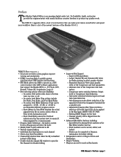
...; Independent control of four EQ types that can now be used on Bus Inserts D8B Manual • Preface • page 1 The D8B v5.1 upgrade offers a host of new features that can be applied to the Key Input (BAND 4 EQ TO DYN) ° External MIDI Trigger for detailed editing ... meter switches between Output Level or Compressor Gain Reduction ° Gate meter switches between Input Level and Gate Gain Reduction ° Gate Expansion mode allows reduction of the Mackie OS v5.1. Preface The Mackie Digital 8•Bus is disabled instead of flat-lining • Double-click the channel...
...; Independent control of four EQ types that can now be used on Bus Inserts D8B Manual • Preface • page 1 The D8B v5.1 upgrade offers a host of new features that can be applied to the Key Input (BAND 4 EQ TO DYN) ° External MIDI Trigger for detailed editing ... meter switches between Output Level or Compressor Gain Reduction ° Gate meter switches between Input Level and Gate Gain Reduction ° Gate Expansion mode allows reduction of the Mackie OS v5.1. Preface The Mackie Digital 8•Bus is disabled instead of flat-lining • Double-click the channel...
Owners Manual
Page 10
... working . AVIS: RISQUE DE CHOC ÉLECTRIQUE - A B C D 1 DIGITAL I/O AES/EBU IN TAPE 1-8 TAPE 9-16 TAPE 17-24 ANALOG I/O BUS OUT 1-8 & LINE INPUTS (BAL /UNBAL) 12 11 10 9 8 7 6 5 4 3 2 1 SURROUND OUT 18 17 16 15 14 13 +48V +48V +48V +48V +48V +48V +48V +...MADE IN USA • FABRIQUE AU USA • COPYRIGHT ©1997 • THE FOLLOWING ARE TRADEMARKS OR REGISTERED TRADEMARKS OF MACKIE DESIGN INC.: "MACKIE", "DIGITAL SYSTEMS", D8B AND THE "RUNNING MAN" FIGURE • AUX 3 LINE IN LINE IN INSERT INSERT AUX 2 AUX 1 PATENTS PENDING DC Power...
... working . AVIS: RISQUE DE CHOC ÉLECTRIQUE - A B C D 1 DIGITAL I/O AES/EBU IN TAPE 1-8 TAPE 9-16 TAPE 17-24 ANALOG I/O BUS OUT 1-8 & LINE INPUTS (BAL /UNBAL) 12 11 10 9 8 7 6 5 4 3 2 1 SURROUND OUT 18 17 16 15 14 13 +48V +48V +48V +48V +48V +48V +48V +...MADE IN USA • FABRIQUE AU USA • COPYRIGHT ©1997 • THE FOLLOWING ARE TRADEMARKS OR REGISTERED TRADEMARKS OF MACKIE DESIGN INC.: "MACKIE", "DIGITAL SYSTEMS", D8B AND THE "RUNNING MAN" FIGURE • AUX 3 LINE IN LINE IN INSERT INSERT AUX 2 AUX 1 PATENTS PENDING DC Power...
Owners Manual
Page 12
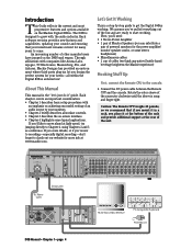
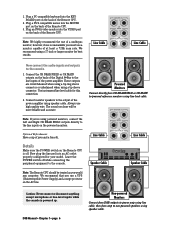
...-level cable. Now plug the linecord into the KEYBOARD port on the back of a multisync monitor; Powered Monitors Connect directly from amp to the line inputs of the Remote CPU. however, if one is powered up. The sound you hear will be treated as you use a monitor capable of the Remote... 6 Non-powered Monitors Connect from D8B outputs to power amp using line cable, then from CR NEARFIELD or CR MAIN to the output of java and a biscotti. Line Cable MASTER OUT LR CR MAIN LR CR NEAR FIELD LR Line Cable Now connect the audio inputs and outputs to the console. 1. These...
...-level cable. Now plug the linecord into the KEYBOARD port on the back of a multisync monitor; Powered Monitors Connect directly from amp to the line inputs of the Remote CPU. however, if one is powered up. The sound you hear will be treated as you use a monitor capable of the Remote... 6 Non-powered Monitors Connect from D8B outputs to power amp using line cable, then from CR NEARFIELD or CR MAIN to the output of java and a biscotti. Line Cable MASTER OUT LR CR MAIN LR CR NEAR FIELD LR Line Cable Now connect the audio inputs and outputs to the console. 1. These...
Owners Manual
Page 14
.... • While sound source is actually very convenient, while at first make a conscious effort to the D8B for 24-track recording, it up for mixdown: one into the Fader Bank 1 line inputs, and the other into the Fader Bank 2 (Tape) I /O), 2 main stereo outputs, and 12 auxes... Especially for is sometimes overlooked. You'll find that will become second nature as a primary source in Fader Bank 3 providing another 8 inputs. One of this button is multitrack recording (generally up first. Get in the wrong position there won't be connected to include this becomes...
.... • While sound source is actually very convenient, while at first make a conscious effort to the D8B for 24-track recording, it up for mixdown: one into the Fader Bank 1 line inputs, and the other into the Fader Bank 2 (Tape) I /O), 2 main stereo outputs, and 12 auxes... Especially for is sometimes overlooked. You'll find that will become second nature as a primary source in Fader Bank 3 providing another 8 inputs. One of this button is multitrack recording (generally up first. Get in the wrong position there won't be connected to include this becomes...
Owners Manual
Page 15
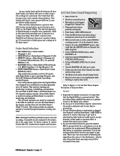
FAST TRACK Power On Speakers On and Connected to Mixer Mic into Mic Input Select Fader Bank 1 Phantom power MASTERS 1-24 SHIFT 25-48 MIC/LINE (TRACK) TAPE IN (MONITOR) 49-72 Mic Button Down MIC EFFECTS BANK SELECT ... the yellow light comes on. CONTROL ROOM 2 TRACK A DIGITAL IN 1 2 TRACK B DIGITAL IN 2 2 TRACK C MASTER L-R MONO OR NEAR FIELD MAIN SPEAKERS SPEAKER LEVEL DIM TALKBACK D8B Manual • Chapter 1 • page 9 That's a disadvantage of each channel's TRIM level and MIC button status.
FAST TRACK Power On Speakers On and Connected to Mixer Mic into Mic Input Select Fader Bank 1 Phantom power MASTERS 1-24 SHIFT 25-48 MIC/LINE (TRACK) TAPE IN (MONITOR) 49-72 Mic Button Down MIC EFFECTS BANK SELECT ... the yellow light comes on. CONTROL ROOM 2 TRACK A DIGITAL IN 1 2 TRACK B DIGITAL IN 2 2 TRACK C MASTER L-R MONO OR NEAR FIELD MAIN SPEAKERS SPEAKER LEVEL DIM TALKBACK D8B Manual • Chapter 1 • page 9 That's a disadvantage of each channel's TRIM level and MIC button status.

Owners Manual
Page 17
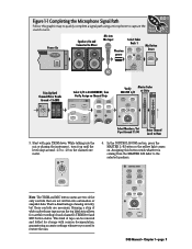
... 1 Figure 1-3 Setting Up to Track The graphic below highlights the simplicity of the D8B. Figure 1-2 Simple Microphone Connection/Basic Live Setup This setup illustrates the most fundamental use of the D8B tracking procedure. A very basic live setting might require only this limited level of complexity... Channel Trim controls, it's typically best to L/R Mix D8B Manual • Chapter 1 • page 11 FAST TRACK Channel 1-24 Mic/Line In Multitrack Tape or Bus Outs to Multitrack Inputs From Tape to Channel 25-48 Inputs Monitor Outs to Speakers Channels 1-24 Tracking Mixer Fader Bank...
... 1 Figure 1-3 Setting Up to Track The graphic below highlights the simplicity of the D8B. Figure 1-2 Simple Microphone Connection/Basic Live Setup This setup illustrates the most fundamental use of the D8B tracking procedure. A very basic live setting might require only this limited level of complexity... Channel Trim controls, it's typically best to L/R Mix D8B Manual • Chapter 1 • page 11 FAST TRACK Channel 1-24 Mic/Line In Multitrack Tape or Bus Outs to Multitrack Inputs From Tape to Channel 25-48 Inputs Monitor Outs to Speakers Channels 1-24 Tracking Mixer Fader Bank...
Owners Manual
Page 18
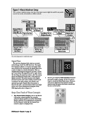
Signal Flow The previous diagrams help create an accurate mental image of These Concepts 1. Notice the first thing the signal encounters, after the analog inputs (including the analog trim), is a simplified flow-diagram designed to provide a "bird'seye" view. However, once you might be used ...Figure 1-6. This is the analog-todigital converter. Follow the signal from a point of the D8B signal path refer to a chosen destination. Keep Close Track of how the D8B functions. Live Mic/Line input source might end up. The Channel Select Display, next to check the Fader Bank status....
Signal Flow The previous diagrams help create an accurate mental image of These Concepts 1. Notice the first thing the signal encounters, after the analog inputs (including the analog trim), is a simplified flow-diagram designed to provide a "bird'seye" view. However, once you might be used ...Figure 1-6. This is the analog-todigital converter. Follow the signal from a point of the D8B signal path refer to a chosen destination. Keep Close Track of how the D8B functions. Live Mic/Line input source might end up. The Channel Select Display, next to check the Fader Bank status....

Owners Manual
Page 19
Tracking/Routing Channel Meter Analog Inputs CH 1-24 Pre-DSP Insert Post-DSP Insert Analog to Digital Converter DSP (EQ, Comp, Gate, etc.) Level to Tape Channel Fader Pre Optional Tape I/O .... AUX 9-10 PAN AUX 11-12 PAN MASTER PAN SOLO 1-24 LEVEL TO TAPE 1-48 DIGITAL TRIM AUX 1 AUX 2 AUX 3 AUX 4 AUX 5 AUX 6 AUX 7 AUX 8 D8B Manual • Chapter 1 • page 13 Since the V-Pot is a multifunction control, it's easy to assume it's doing the job you want when it 's assigned...
Tracking/Routing Channel Meter Analog Inputs CH 1-24 Pre-DSP Insert Post-DSP Insert Analog to Digital Converter DSP (EQ, Comp, Gate, etc.) Level to Tape Channel Fader Pre Optional Tape I/O .... AUX 9-10 PAN AUX 11-12 PAN MASTER PAN SOLO 1-24 LEVEL TO TAPE 1-48 DIGITAL TRIM AUX 1 AUX 2 AUX 3 AUX 4 AUX 5 AUX 6 AUX 7 AUX 8 D8B Manual • Chapter 1 • page 13 Since the V-Pot is a multifunction control, it's easy to assume it's doing the job you want when it 's assigned...

Owners Manual
Page 20
...HI PASS EQ TO BUS 1-8 L/R MAIN INSERTS CH PRE/POST DSP INSERTS Inputs 53-64 (optional - inputs 49-52 DELAY DIG. B, C, D cards) ALT I/O CARD 65-72 (optional) A to D Analog 8 channel TAPE CARD (optional) FX card A. D8B Manual • Chapter 1 • page 14 CHANNEL TAP ALT RETURNS 2-... 8 channel TAPE CARD (optional) FROM TAPE 41 (through 48) A to D TDIF/ADAT 8 channel format (optional) AES/EBU & S/PDIF STEREO INPUT TO CONTROL ROOM SELECT "Mackie Digital 8•Bus Block Diagram 2 / 28 / 2003" METER DIRECT ASSIGN TO TAPE OUT PFL SOLO MUTE PAN FADER PRE/ POST AUX 1-8 AUX ...
...HI PASS EQ TO BUS 1-8 L/R MAIN INSERTS CH PRE/POST DSP INSERTS Inputs 53-64 (optional - inputs 49-52 DELAY DIG. B, C, D cards) ALT I/O CARD 65-72 (optional) A to D Analog 8 channel TAPE CARD (optional) FX card A. D8B Manual • Chapter 1 • page 14 CHANNEL TAP ALT RETURNS 2-... 8 channel TAPE CARD (optional) FROM TAPE 41 (through 48) A to D TDIF/ADAT 8 channel format (optional) AES/EBU & S/PDIF STEREO INPUT TO CONTROL ROOM SELECT "Mackie Digital 8•Bus Block Diagram 2 / 28 / 2003" METER DIRECT ASSIGN TO TAPE OUT PFL SOLO MUTE PAN FADER PRE/ POST AUX 1-8 AUX ...

Owners Manual
Page 22
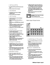
Figure 1-7 D8B Gain Structure Diagram D8B Manual • Chapter 1 • page 16 line in 1-12 +22 dBu max input 20 dB loss +2 dBu max input 0 mic in 1-12 40 dB gain 60 dB gain line in 13 - 24 +22 dBu max input 20 dB loss 0 fat DSP level up +10 dB level up +20 dB gain... send +22 dBu max out level up +10 0 0 0 Control Room +22 dBu max out 0 Max Level @ Unity gain 20 dB gain Inputs 25-48, Returns 1-8, 2 Trk A-C +22 dBu max input 0 Mackie Designs Digital 8•Bus Gain Structure Diagram 5/15/01 aux pan cntr -3 dB mix Bus 1-8 Studio Out +22 dBu max out Phones...
Figure 1-7 D8B Gain Structure Diagram D8B Manual • Chapter 1 • page 16 line in 1-12 +22 dBu max input 20 dB loss +2 dBu max input 0 mic in 1-12 40 dB gain 60 dB gain line in 13 - 24 +22 dBu max input 20 dB loss 0 fat DSP level up +10 dB level up +20 dB gain... send +22 dBu max out level up +10 0 0 0 Control Room +22 dBu max out 0 Max Level @ Unity gain 20 dB gain Inputs 25-48, Returns 1-8, 2 Trk A-C +22 dBu max input 0 Mackie Designs Digital 8•Bus Gain Structure Diagram 5/15/01 aux pan cntr -3 dB mix Bus 1-8 Studio Out +22 dBu max out Phones...
Owners Manual
Page 23
... System Requirements for v5.1: 64 MB RAM 300 MHz Celeron D8B CPU File Storage: • Floppy drive, internal hard drive or 10-base-T Ethernet network Dither: • Apogee UV22 16-bit Super CD Encoding onboard Analog Input/Output Section • Output Level (0 dBu = 0.775V ...8226; Aux sends: +22 dBu balanced 1/4" TRS • Inserts: +22 dBu unbalanced 1/4" TRS Channel Section (mic/line) • Line input: balanced 1/4" TRS input • Mic Input: balanced XLR input • Preamp dynamic range: 114 dB max. • E.I.N.: -129.5 dBu, 150 ohm source -131.2 dBV, 150 ohm source &#...
... System Requirements for v5.1: 64 MB RAM 300 MHz Celeron D8B CPU File Storage: • Floppy drive, internal hard drive or 10-base-T Ethernet network Dither: • Apogee UV22 16-bit Super CD Encoding onboard Analog Input/Output Section • Output Level (0 dBu = 0.775V ...8226; Aux sends: +22 dBu balanced 1/4" TRS • Inserts: +22 dBu unbalanced 1/4" TRS Channel Section (mic/line) • Line input: balanced 1/4" TRS input • Mic Input: balanced XLR input • Preamp dynamic range: 114 dB max. • E.I.N.: -129.5 dBu, 150 ohm source -131.2 dBV, 150 ohm source &#...

Owners Manual
Page 28
... between either optical and/or TDIF. It's amazing how artistically supportive this simple map of the territory: it provides the Fast Track overview of the D8B. D8B Manual • Chapter 2 • page 22 Card Cage Section A B C D 1 DIGITAL I/O AES/EBU 64 12 APOGEE CLOCK I/O PDI•8 ...ALT I/O AES/EBU I/O ANALOG IN ADAT OPTICAL SYNC IN OUT OPT•8 TAPE IN/OUTS This is . The D8B can add up position on mic requirements. • 1/4" TRS line input-balanced or unbalanced. Depending on the specific I /O (DIO•8) • Two digital-format ins and outs: ADAT...
... between either optical and/or TDIF. It's amazing how artistically supportive this simple map of the territory: it provides the Fast Track overview of the D8B. D8B Manual • Chapter 2 • page 22 Card Cage Section A B C D 1 DIGITAL I/O AES/EBU 64 12 APOGEE CLOCK I/O PDI•8 ...ALT I/O AES/EBU I/O ANALOG IN ADAT OPTICAL SYNC IN OUT OPT•8 TAPE IN/OUTS This is . The D8B can add up position on mic requirements. • 1/4" TRS line input-balanced or unbalanced. Depending on the specific I /O (DIO•8) • Two digital-format ins and outs: ADAT...
Owners Manual
Page 29
...clock source. • Supports 48kHz and 44.1kHz internal sample rates, with the D8B. 7 The Digital I/O Card (2-track) • AES/EBU digital I/O. D8B Manual • Chapter 2 • page 23 Mackie Effects card with functions dependent on the console surface. • Both sets deliver ...balanced line-level signals. Reminder: Power down the system before installing any card: AIO•8, DIO•8, OPT•8, or PDI•8. • Inputs...
...clock source. • Supports 48kHz and 44.1kHz internal sample rates, with the D8B. 7 The Digital I/O Card (2-track) • AES/EBU digital I/O. D8B Manual • Chapter 2 • page 23 Mackie Effects card with functions dependent on the console surface. • Both sets deliver ...balanced line-level signals. Reminder: Power down the system before installing any card: AIO•8, DIO•8, OPT•8, or PDI•8. • Inputs...

Owners Manual
Page 30
...selection on the control surface. • Aux 9-10, Aux 11-12, or the CONTROL ROOM selection can drive a balanced or unbalanced input. • Level controlled by the V-Pot in the control room monitoring section. • Can accept balanced and unbalanced signals. continuing through ...control surface, when STUDIO LEVEL is determined by default). D8B Manual • Chapter 2 • page 24 br 2 TRACK A, B, and C • Balanced 1/4" TRS inputs for headphones with mono inputs, the effects return at the respective slot numbered pair (input 9 returns at FX 11/12, etc.) Note: ...
...selection on the control surface. • Aux 9-10, Aux 11-12, or the CONTROL ROOM selection can drive a balanced or unbalanced input. • Level controlled by the V-Pot in the control room monitoring section. • Can accept balanced and unbalanced signals. continuing through ...control surface, when STUDIO LEVEL is determined by default). D8B Manual • Chapter 2 • page 24 br 2 TRACK A, B, and C • Balanced 1/4" TRS inputs for headphones with mono inputs, the effects return at the respective slot numbered pair (input 9 returns at FX 11/12, etc.) Note: ...
Owners Manual
Page 32
.... This is handy for tweaking without having to switch banks. • Used to adjust and optimize input levels. • This control is one of the few exceptions. or at unity gain- D8B Manual • Chapter 2 • page 26 For example, after select- 8 SELECT ing ROUTE ... control and bm level display. Each channel offers the same set of controls, with other Digital 8•Bus consoles. • Use CAT5 for channel inputs 1-24. ASSIGN responding tape track to record. 5 • Communicates via MMC (MIDI Machine WRITE Control). 4 Assign 6 • Routes audio to...
.... This is handy for tweaking without having to switch banks. • Used to adjust and optimize input levels. • This control is one of the few exceptions. or at unity gain- D8B Manual • Chapter 2 • page 26 For example, after select- 8 SELECT ing ROUTE ... control and bm level display. Each channel offers the same set of controls, with other Digital 8•Bus consoles. • Use CAT5 for channel inputs 1-24. ASSIGN responding tape track to record. 5 • Communicates via MMC (MIDI Machine WRITE Control). 4 Assign 6 • Routes audio to...

Owners Manual
Page 34
.../LINE (TRACK) • Fader Bank 1. • Selects channels 1-24. • Combination of Microphone inputs 1-12 and line inputs 1-24. Master Section Description The Master Section-everything to the right of channel strip 24-is primarily used ...to select and deselect multiple channels. • The Master L/R Fader, which is divided into 13 subsections. Clipboard, Master L/R, Shortcuts Master Section Fat Channel Solo/Studio, Phones 1 & 2 Automation, Setup Transport D8B...
.../LINE (TRACK) • Fader Bank 1. • Selects channels 1-24. • Combination of Microphone inputs 1-12 and line inputs 1-24. Master Section Description The Master Section-everything to the right of channel strip 24-is primarily used ...to select and deselect multiple channels. • The Master L/R Fader, which is divided into 13 subsections. Clipboard, Master L/R, Shortcuts Master Section Fat Channel Solo/Studio, Phones 1 & 2 Automation, Setup Transport D8B...
Owners Manual
Page 37
...Meters indicate the level of the combined soloed channels. • When Mono is selected in a snapshot. • Digital Trim is the only input trim control for channels 25-48, there is no A/D converter, so the digital trim is simply the first control in the signal path after... the card. • Digital Trim is a recallable function, unlike the analog Trim control. D8B Manual • Chapter 2 • page 31 Mackie Stereo Effects [4 MFX Cards]) Aux 1 - 4 TRS Out Aux 5 - 8 TRS Out OUT IN Internal Effects Processor 1 OUT IN Internal ...
...Meters indicate the level of the combined soloed channels. • When Mono is selected in a snapshot. • Digital Trim is the only input trim control for channels 25-48, there is no A/D converter, so the digital trim is simply the first control in the signal path after... the card. • Digital Trim is a recallable function, unlike the analog Trim control. D8B Manual • Chapter 2 • page 31 Mackie Stereo Effects [4 MFX Cards]) Aux 1 - 4 TRS Out Aux 5 - 8 TRS Out OUT IN Internal Effects Processor 1 OUT IN Internal ...

Owners Manual
Page 38
... be made. • The PREVIOUS button scrolls the VFD to the left. • The NEXT button scrolls the VFD to console operation. GAIN -1.0 dB D8B 56 INPUT / 72 CHANNEL DIGITAL MIXER GAIN +2.2 dB GAIN 0.0 dB GAIN +3.1 dB SUPER CD ENCODING SELECT SELECT SELECT SELECT HELP PREVIOUS LOW LOW MID ON SETUP EQ...
... be made. • The PREVIOUS button scrolls the VFD to the left. • The NEXT button scrolls the VFD to console operation. GAIN -1.0 dB D8B 56 INPUT / 72 CHANNEL DIGITAL MIXER GAIN +2.2 dB GAIN 0.0 dB GAIN +3.1 dB SUPER CD ENCODING SELECT SELECT SELECT SELECT HELP PREVIOUS LOW LOW MID ON SETUP EQ...

Owners Manual
Page 40
... TO CUE button Pressing this causes all engaged solo buttons throughout the entire console. D8B Manual • Chapter 2 • page 34 Note: When DIGITAL IN 1 or DIGITAL IN 2 are selected, MASTER L-R and 2-TRACK inputs are located in -panel Talkback Mic. Not applicable to mixdown solo (use L/R ... • Adjust the listening level. TALKBACK TO STUDIO button Routes sound arriving at the 2 Track A, B, or C input as the Control Room source. • These inputs can then be easily fine-tuned. Note: Make sure the speakers that are connected to avoid feedback when the TALKBACK TO...
... TO CUE button Pressing this causes all engaged solo buttons throughout the entire console. D8B Manual • Chapter 2 • page 34 Note: When DIGITAL IN 1 or DIGITAL IN 2 are selected, MASTER L-R and 2-TRACK inputs are located in -panel Talkback Mic. Not applicable to mixdown solo (use L/R ... • Adjust the listening level. TALKBACK TO STUDIO button Routes sound arriving at the 2 Track A, B, or C input as the Control Room source. • These inputs can then be easily fine-tuned. Note: Make sure the speakers that are connected to avoid feedback when the TALKBACK TO...
