
Owners Manual
Page 2
... should be followed. 5. PORTABLE CART WARNING Carts and stands - Power supply cords should be routed so that objects do not expose this Mackie product and in a commercial installation. The power-supply cord or the plug has been damaged; or E. Servicing - This apparatus does not...operating and other devices which case the user will be situated on the console. Water and Moisture - Power Cord Protection - Do not remove the inner power supply cover. 14. WARNING - Retain Instructions - This Mackie product should be situated so that may cause harmful interference to rain;...
... should be followed. 5. PORTABLE CART WARNING Carts and stands - Power supply cords should be routed so that objects do not expose this Mackie product and in a commercial installation. The power-supply cord or the plug has been damaged; or E. Servicing - This apparatus does not...operating and other devices which case the user will be situated on the console. Water and Moisture - Power Cord Protection - Do not remove the inner power supply cover. 14. WARNING - Retain Instructions - This Mackie product should be situated so that may cause harmful interference to rain;...

Owners Manual
Page 4
...Chapter 1: Getting Ready 3 Introduction ...4 About This Manual ...4 Let's Get It Working ...4 Hooking Stuff Up ...4 A New Way of Thinking: Four Consoles in One 7 Fader Bank Selection...8 Let's Get Some Sound Happening ...8 Figure 1-1 Completing the Microphone Signal Path ...9 Signal Routing Concept ...10 Figure... 1-4 Basic Mixdown Setup ...12 Keep Close Track of Contents • page i Mackie Stereo Effects [4 MFX Cards 31 Fat Channel Section...32 Studio/Solo Section ...33 Phones/Cue Mix Section ...34 D8B Manual • Table of These Concepts ...12 Figure 1-5 Signal-Flow Diagram ...13...
...Chapter 1: Getting Ready 3 Introduction ...4 About This Manual ...4 Let's Get It Working ...4 Hooking Stuff Up ...4 A New Way of Thinking: Four Consoles in One 7 Fader Bank Selection...8 Let's Get Some Sound Happening ...8 Figure 1-1 Completing the Microphone Signal Path ...9 Signal Routing Concept ...10 Figure... 1-4 Basic Mixdown Setup ...12 Keep Close Track of Contents • page i Mackie Stereo Effects [4 MFX Cards 31 Fat Channel Section...32 Studio/Solo Section ...33 Phones/Cue Mix Section ...34 D8B Manual • Table of These Concepts ...12 Figure 1-5 Signal-Flow Diagram ...13...
Owners Manual
Page 7
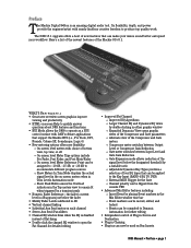
...nearly limitless creative freedom to Dynamic Automation for the Gate ° Channel polarity can be flipped from the console VFD • Advanced Mix Editor features including: ° Insert Event by a variable ratio ° Adjustable... is an amazing digital audio tool. Here's a list of the newest features of new features that support the Mackie HUI (i.e., Pro Tools, DP3, Nuendo, Cubase SX, Soundscape, Logic 6) • New metering options offer more...Plug-ins can now be used on Bus Inserts D8B Manual • Preface • page 1 The D8B v5.1 upgrade offers a host of the Mackie OS v5.1.
...nearly limitless creative freedom to Dynamic Automation for the Gate ° Channel polarity can be flipped from the console VFD • Advanced Mix Editor features including: ° Insert Event by a variable ratio ° Adjustable... is an amazing digital audio tool. Here's a list of the newest features of new features that support the Mackie HUI (i.e., Pro Tools, DP3, Nuendo, Cubase SX, Soundscape, Logic 6) • New metering options offer more...Plug-ins can now be used on Bus Inserts D8B Manual • Preface • page 1 The D8B v5.1 upgrade offers a host of the Mackie OS v5.1.
Owners Manual
Page 10
...IN USA • FABRIQUE AU USA • COPYRIGHT ©1997 • THE FOLLOWING ARE TRADEMARKS OR REGISTERED TRADEMARKS OF MACKIE DESIGN INC.: "MACKIE", "DIGITAL SYSTEMS", D8B AND THE "RUNNING MAN" FIGURE • AUX 3 LINE IN LINE IN INSERT INSERT AUX 2 AUX 1 PATENTS PENDING DC... INTERFERENCE RECEIVED THAT MAY CAUSE UNDESIRED OPERATION SERIAL NUMBER MANUFACTURING DATE 120V 60Hz, 2.8A 120/230V 1.0/0.5A CONSOLE DATA PARALLEL KEYBOARD MOUSE CONCEIVED, DESIGNED, AND MANUFACTURED BY MACKIE DESIGNS INC • WOODINVILLE • WA • USA • MADE IN USA • FABRIQUE...
...IN USA • FABRIQUE AU USA • COPYRIGHT ©1997 • THE FOLLOWING ARE TRADEMARKS OR REGISTERED TRADEMARKS OF MACKIE DESIGN INC.: "MACKIE", "DIGITAL SYSTEMS", D8B AND THE "RUNNING MAN" FIGURE • AUX 3 LINE IN LINE IN INSERT INSERT AUX 2 AUX 1 PATENTS PENDING DC... INTERFERENCE RECEIVED THAT MAY CAUSE UNDESIRED OPERATION SERIAL NUMBER MANUFACTURING DATE 120V 60Hz, 2.8A 120/230V 1.0/0.5A CONSOLE DATA PARALLEL KEYBOARD MOUSE CONCEIVED, DESIGNED, AND MANUFACTURED BY MACKIE DESIGNS INC • WOODINVILLE • WA • USA • MADE IN USA • FABRIQUE...

Owners Manual
Page 11
CONSOLE DATA PARALLEL KEYBOARD MOUSE CONCEIVED, DESIGNED, AND MANUFACTURED BY MACKIE DESIGNS INC • WOODINVILLE • WA • USA • MADE IN USA • FABRIQUE AU USA • COPYRIGHT ©1997 • THE FOLLOWING ARE TRADEMARKS OR REGISTERED TRADEMARKS OF MACKIE DESIGN INC.: "MACKIE", "DIGITAL SYSTEMS", D8B AND THE "RUNNING MAN" FIGURE • D8B Manual • Chapter...
CONSOLE DATA PARALLEL KEYBOARD MOUSE CONCEIVED, DESIGNED, AND MANUFACTURED BY MACKIE DESIGNS INC • WOODINVILLE • WA • USA • MADE IN USA • FABRIQUE AU USA • COPYRIGHT ©1997 • THE FOLLOWING ARE TRADEMARKS OR REGISTERED TRADEMARKS OF MACKIE DESIGN INC.: "MACKIE", "DIGITAL SYSTEMS", D8B AND THE "RUNNING MAN" FIGURE • D8B Manual • Chapter...
Owners Manual
Page 12
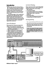
...amplifier using a tip-sleeve connector. Connect the CR NEAR FIELD or CR MAIN outputs on the AC line. D8B Manual • Chapter 1 • page 6 Non-powered Monitors Connect from D8B outputs to power amp using line cable, then from CR NEARFIELD or CR MAIN to the output of the... Digital 8•Bus to the console. 1. 1. We recommend using powered monitors, connect the Left and Right CR NEAR FIELD ...
...amplifier using a tip-sleeve connector. Connect the CR NEAR FIELD or CR MAIN outputs on the AC line. D8B Manual • Chapter 1 • page 6 Non-powered Monitors Connect from D8B outputs to power amp using line cable, then from CR NEARFIELD or CR MAIN to the output of the... Digital 8•Bus to the console. 1. 1. We recommend using powered monitors, connect the Left and Right CR NEAR FIELD ...

Owners Manual
Page 13
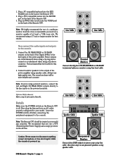
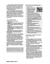
...25-48 MIC/LINE (TRACK) TAPE IN (MONITOR) 49-72 EFFECTS BANK SELECT MBuVIDsirIt1FCu-8aaoldnMGteraroroslBltueearprsnssk11-48-8 D8B Manual • Chapter 1 • page 7 The Digital 8•Bus takes a few moments ... four completely different sets of fader levels. • Do the same for channel 1, the console is turned all peripherals (processors, recorders, interfaces, etc.). ALT Return 1-8 MASTERS 1-24 SHIFT...49-72 EFFECTS BANK SELECT Now that SPEAKER LEVEL V-Pot is ready to load the Mackie Real Time OS (Operating System) and initialize the DSPs. These buttons let you 've...
...25-48 MIC/LINE (TRACK) TAPE IN (MONITOR) 49-72 EFFECTS BANK SELECT MBuVIDsirIt1FCu-8aaoldnMGteraroroslBltueearprsnssk11-48-8 D8B Manual • Chapter 1 • page 7 The Digital 8•Bus takes a few moments ... four completely different sets of fader levels. • Do the same for channel 1, the console is turned all peripherals (processors, recorders, interfaces, etc.). ALT Return 1-8 MASTERS 1-24 SHIFT...49-72 EFFECTS BANK SELECT Now that SPEAKER LEVEL V-Pot is ready to load the Mackie Real Time OS (Operating System) and initialize the DSPs. These buttons let you 've...
Owners Manual
Page 14
... tons of following the signal from the source to play with. One of Fader Bank 1 and Fader Bank 2 as two separate mixing consoles, where Fader Bank 1 is used for tracking and Fader Bank 2 is multitrack recording (generally up first. You can easily be connected ... Be sure the microphone or instrument is plugged into the Fader Bank 2 (Tape) I /O), 2 main stereo outputs, and 12 auxes. D8B Manual • Chapter 1 • page 8 your most consoles taking up green. • In the CONTROL ROOM section, select MASTER L-R. • Select the desired SPEAKERS in your spouse will love ...
... tons of following the signal from the source to play with. One of Fader Bank 1 and Fader Bank 2 as two separate mixing consoles, where Fader Bank 1 is used for tracking and Fader Bank 2 is multitrack recording (generally up first. You can easily be connected ... Be sure the microphone or instrument is plugged into the Fader Bank 2 (Tape) I /O), 2 main stereo outputs, and 12 auxes. D8B Manual • Chapter 1 • page 8 your most consoles taking up green. • In the CONTROL ROOM section, select MASTER L-R. • Select the desired SPEAKERS in your spouse will love ...

Owners Manual
Page 16
.... Figure 1-3 demonstrates a tracking setup. Be sure the SPEAKER button is lit that corresponds to your monitor system connection-that 's routed though the D8B to the monitor system. Slowly raise the level of the Channel One fader until you put the Digital 8•Bus through its paces. Figure 1-2...bus assignment procedure. Start at least four consoles. TRIM LINE TRIM 12 REC/RDY ASSIGN WRITE REC/RDY ASSIGN WRITE 10 10 20 20 30 30 40 40 50 50 60 60 ASSIGNMENT ASSIGN ASSIGN BUS 7 ASSIGN L-R ASSIGN BUS 2 BUS 8 ASSIGN ROUTE TO TAPE D8B Manual • Chapter 1 •...
.... Figure 1-3 demonstrates a tracking setup. Be sure the SPEAKER button is lit that corresponds to your monitor system connection-that 's routed though the D8B to the monitor system. Slowly raise the level of the Channel One fader until you put the Digital 8•Bus through its paces. Figure 1-2...bus assignment procedure. Start at least four consoles. TRIM LINE TRIM 12 REC/RDY ASSIGN WRITE REC/RDY ASSIGN WRITE 10 10 20 20 30 30 40 40 50 50 60 60 ASSIGNMENT ASSIGN ASSIGN BUS 7 ASSIGN L-R ASSIGN BUS 2 BUS 8 ASSIGN ROUTE TO TAPE D8B Manual • Chapter 1 •...
Owners Manual
Page 18
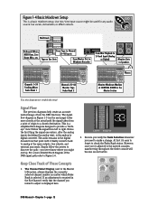
...always displays the currently selected channel number no matter which Fader Bank is a simplified flow-diagram designed to the layered consoles, maneuvering throughout the entire console will become second nature. For a more closely at CONTROL ROOM in the Master Section Use this diagram for any...! This is selected. Figure 1-4 Basic Mixdown Setup This is the analog-todigital converter. Follow the signal from a point of the D8B signal path refer to a chosen destination. If an adjustment is displayed here. FAST TRACK Multitrack Outboard Effects, MIDI Gear, Live Room...
...always displays the currently selected channel number no matter which Fader Bank is a simplified flow-diagram designed to the layered consoles, maneuvering throughout the entire console will become second nature. For a more closely at CONTROL ROOM in the Master Section Use this diagram for any...! This is selected. Figure 1-4 Basic Mixdown Setup This is the analog-todigital converter. Follow the signal from a point of the D8B signal path refer to a chosen destination. If an adjustment is displayed here. FAST TRACK Multitrack Outboard Effects, MIDI Gear, Live Room...
Owners Manual
Page 23
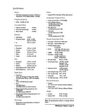
....6" x 27.1" (221mm x 955mm x 688mm) • Remote CPU: 5.25" x 19.0" x 20.0" (133mm x 483mm x 508mm) Weight • Console: • Remote CPU: 73 lbs. (33.1kg) 50 lbs. (22.7kg) Note: All specifications subject to change without notice. level: +4 dBu nominal +22 dBu clipping &#... +60 dB • Line In gain range: -20 dB to +40 dB (channels 1-12) -20 dB to +20 dB (channels 13-24) • Input max. D8B Manual • Chapter 1 • page 17 Specifications Meters: • LED ladders displaying 24 channels, 24 LEDs per channel from -50 to 0 dBFS (0 dBFS = +20 dBu...
....6" x 27.1" (221mm x 955mm x 688mm) • Remote CPU: 5.25" x 19.0" x 20.0" (133mm x 483mm x 508mm) Weight • Console: • Remote CPU: 73 lbs. (33.1kg) 50 lbs. (22.7kg) Note: All specifications subject to change without notice. level: +4 dBu nominal +22 dBu clipping &#... +60 dB • Line In gain range: -20 dB to +40 dB (channels 1-12) -20 dB to +20 dB (channels 13-24) • Input max. D8B Manual • Chapter 1 • page 17 Specifications Meters: • LED ladders displaying 24 channels, 24 LEDs per channel from -50 to 0 dBFS (0 dBFS = +20 dBu...

Owners Manual
Page 24
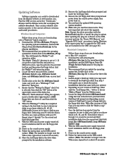
8.7" (221mm) Physical Dimensions 37.6" (955mm) D8B CONSOLE SHIPPING WEIGHT 73 lbs. (33.1 kg) 17.25" (43.8cm) 27.1" (688mm) 20" (50.8cm) 5.25" (13.3cm) 3U D8B CPU SHIPPING WEIGHT 50 lbs. (22.7 kg) D8B Manual • Chapter 1 • page 18 CPU 19.00" (48.3cm)
8.7" (221mm) Physical Dimensions 37.6" (955mm) D8B CONSOLE SHIPPING WEIGHT 73 lbs. (33.1 kg) 17.25" (43.8cm) 27.1" (688mm) 20" (50.8cm) 5.25" (13.3cm) 3U D8B CPU SHIPPING WEIGHT 50 lbs. (22.7 kg) D8B Manual • Chapter 1 • page 18 CPU 19.00" (48.3cm)
Owners Manual
Page 25
...disks from the computer, be downloaded from the Mackie website at www.mackie.com. Download the .ZIP files d8b5xxxx_PC.zip for the operating system installation, and the D8B Plug-in update. The default "Unzip To" directory is about 30 seconds.) D8B Manual • Chapter 1 • page ... Macintosh Computers Follow these steps if you update the operating system first. Double-click on your version of the dialog box. 7. With the D8B console power supply turned off , insert installation disk #1 into drive A:\ and then click the "OK" button. 8. Remove the 2nd floppy disk...
...disks from the computer, be downloaded from the Mackie website at www.mackie.com. Download the .ZIP files d8b5xxxx_PC.zip for the operating system installation, and the D8B Plug-in update. The default "Unzip To" directory is about 30 seconds.) D8B Manual • Chapter 1 • page ... Macintosh Computers Follow these steps if you update the operating system first. Double-click on your version of the dialog box. 7. With the D8B console power supply turned off , insert installation disk #1 into drive A:\ and then click the "OK" button. 8. Remove the 2nd floppy disk...
Owners Manual
Page 26
Remove the 3rd floppy disk when prompted and power down the console power supply, then power back on the D8B, you . They have the updated D8B operating system installed. 14. Launch ShrinkWrap. 4. Summary This chapter has been specifically designed to insert a floppy disk into the floppy disk drive. ...Feel free to jump ahead, but keep in mind that you'll probably need to you must use these steps for steps 3-6 in the D8B. D8B Manual • Chapter 1 • page 20 You must perform the "Erase UFX Memory" and "Upgrade UFX Cards" procedures (under Windows in the...
Remove the 3rd floppy disk when prompted and power down the console power supply, then power back on the D8B, you . They have the updated D8B operating system installed. 14. Launch ShrinkWrap. 4. Summary This chapter has been specifically designed to insert a floppy disk into the floppy disk drive. ...Feel free to jump ahead, but keep in mind that you'll probably need to you must use these steps for steps 3-6 in the D8B. D8B Manual • Chapter 1 • page 20 You must perform the "Erase UFX Memory" and "Upgrade UFX Cards" procedures (under Windows in the...

Owners Manual
Page 28
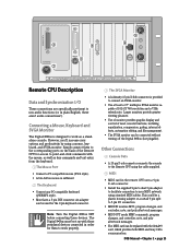
... addition, the bus outputs in the optional I /O card, these connectors. Depending on the specific I /O cards of the D8B. No matter how fast you want-or need-to get started, take advantage of this console is where you can be routed out the tape outputs. • FROM TAPE (INPUT...) - D8B Manual • Chapter 2 • page 22 Card Cage Section A B C D 1 DIGITAL I/O AES/EBU 64 12 APOGEE CLOCK I/O PDI•8 ANALOG ...
... addition, the bus outputs in the optional I /O card, these connectors. Depending on the specific I /O cards of the D8B. No matter how fast you want-or need-to get started, take advantage of this console is where you can be routed out the tape outputs. • FROM TAPE (INPUT...) - D8B Manual • Chapter 2 • page 22 Card Cage Section A B C D 1 DIGITAL I/O AES/EBU 64 12 APOGEE CLOCK I/O PDI•8 ANALOG ...
Owners Manual
Page 29
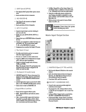
...or the MASTER L-R outputs. • Assignments are assignable to connect with functions dependent on the console surface. • Both sets deliver balanced line-level signals. Mackie Effects card with vari-speed capabilities. • Supports external sample rates between 32kHz and 50kHz. ...digital I /O TALKBACK 9 MASTER OUTputs (1/4" TRS and XLR) • Fed from the Master L/R fader on specific plug-in the Surround window. D8B Manual • Chapter 2 • page 23 Reminder: Power down the system before installing any card: AIO•8, DIO•8, OPT•8,...
...or the MASTER L-R outputs. • Assignments are assignable to connect with functions dependent on the console surface. • Both sets deliver balanced line-level signals. Mackie Effects card with vari-speed capabilities. • Supports external sample rates between 32kHz and 50kHz. ...digital I /O TALKBACK 9 MASTER OUTputs (1/4" TRS and XLR) • Fed from the Master L/R fader on specific plug-in the Surround window. D8B Manual • Chapter 2 • page 23 Reminder: Power down the system before installing any card: AIO•8, DIO•8, OPT•8,...
Owners Manual
Page 31
... split to 5-pin I /O These connections are specifically pertinent to non-audio functions (or, in plain English, these devices. D8B Manual • Chapter 2 • page 25 CONSOLE DATA PARALLEL 4 KEYBOARD 2 3 MOUSE 1 5 6 CONCEIVED, DESIGNED, AND MANUFACTURED BY MACKIE DESIGNS INC • WOODINVILLE • WA • USA • MADE IN USA • FABRIQUE AU USA •...
... split to 5-pin I /O These connections are specifically pertinent to non-audio functions (or, in plain English, these devices. D8B Manual • Chapter 2 • page 25 CONSOLE DATA PARALLEL 4 KEYBOARD 2 3 MOUSE 1 5 6 CONCEIVED, DESIGNED, AND MANUFACTURED BY MACKIE DESIGNS INC • WOODINVILLE • WA • USA • MADE IN USA • FABRIQUE AU USA •...
Owners Manual
Page 32
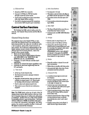
Control Surface Functions We'll divide the D8B control surface into automation or snapshots. We highly recommend this console design. • There are 24 channel strips. • There are not written into two sections, the Channel Strip section and the Master section. ASSIGN...). • Displays return fader levels (Bank 2) when Level to their status should be used to make peer-to-peer connections with other Digital 8•Bus consoles. • Use CAT5 for recording. put (XLR) and the Line Input (1/4" TRS). • Up position selects the line input (1/4" TRS). • Down position...
Control Surface Functions We'll divide the D8B control surface into automation or snapshots. We highly recommend this console design. • There are 24 channel strips. • There are not written into two sections, the Channel Strip section and the Master section. ASSIGN...). • Displays return fader levels (Bank 2) when Level to their status should be used to make peer-to-peer connections with other Digital 8•Bus consoles. • Use CAT5 for recording. put (XLR) and the Line Input (1/4" TRS). • Up position selects the line input (1/4" TRS). • Down position...

Owners Manual
Page 33
... mode overrides Solo Isolate mode. Each LED-segment is configured for Faders to the fader. D8B Manual • Chapter 2 • page 27 bl Mute • Mutes the signal ...Doesn't affect the signal level to the Tape Outputs unless specifically routed to do so, or if console is a built-in the VFD, which controls basic channel parameters. • Pressing and holding ...Solo • Pressing Solo on any channel lets you hear only the soloed channel. • Mackie's exclusive Rude Solo Light flashes incessantly whenever any solo selections. Any channel is always active to...
... mode overrides Solo Isolate mode. Each LED-segment is configured for Faders to the fader. D8B Manual • Chapter 2 • page 27 bl Mute • Mutes the signal ...Doesn't affect the signal level to the Tape Outputs unless specifically routed to do so, or if console is a built-in the VFD, which controls basic channel parameters. • Pressing and holding ...Solo • Pressing Solo on any channel lets you hear only the soloed channel. • Mackie's exclusive Rude Solo Light flashes incessantly whenever any solo selections. Any channel is always active to...

Owners Manual
Page 35
... for smooth fades. • Remotely controls level via the 25-pin D-sub connector labeled BUS OUT 1-8 & SURROUND OUT on the rear of the console. It provides a way to tape outputs (if desired). It also serves as the front/rear pan control for Aux levels and Pan adjustments. Try ...provided the PAN button is active (SHIFT+MASTERS). • Allows more then one SOLO button to the 24 tape outputs, or the ALT I /O returns. D8B Manual • Chapter 2 • page 29 SHIFT Button The SHIFT button serves multiple functions. The BUS 1-8 outputs can also be assigned to be engaged ...
... for smooth fades. • Remotely controls level via the 25-pin D-sub connector labeled BUS OUT 1-8 & SURROUND OUT on the rear of the console. It provides a way to tape outputs (if desired). It also serves as the front/rear pan control for Aux levels and Pan adjustments. Try ...provided the PAN button is active (SHIFT+MASTERS). • Allows more then one SOLO button to the 24 tape outputs, or the ALT I /O returns. D8B Manual • Chapter 2 • page 29 SHIFT Button The SHIFT button serves multiple functions. The BUS 1-8 outputs can also be assigned to be engaged ...
