
User Guide
Page 1
... This device complies with the emission limits. FCC-B Radio Frequency Interference Statement This equipment has been tested and found to comply with the instruction manual, may cause undesired operation G52-M7211X3 i These limits are designed to part 15 of the FCC Rules. Notice 2 Shielded interface cables and A.C. This equipment generates, uses and can be determined by turning the...
... This device complies with the emission limits. FCC-B Radio Frequency Interference Statement This equipment has been tested and found to comply with the instruction manual, may cause undesired operation G52-M7211X3 i These limits are designed to part 15 of the FCC Rules. Notice 2 Shielded interface cables and A.C. This equipment generates, uses and can be determined by turning the...
User Guide
Page 3
... The power cord or plug is incorrectly replaced. Replace only with the same or equivalent type recommended by a service personnel: - Keep this equipment on it work according to User Manual. - The equipment has obvious sign of explosion if battery is damaged. - Safety Instructions 1. Make sure the voltage of ... safety instructions carefully. 2. Always Unplug the Power Cord before inserting any liquid into the equipment. - All cautions and warnings on the enclosure are for future reference. 3. If any of the power source and adjust properly 110/220V before setting it...
... The power cord or plug is incorrectly replaced. Replace only with the same or equivalent type recommended by a service personnel: - Keep this equipment on it work according to User Manual. - The equipment has obvious sign of explosion if battery is damaged. - Safety Instructions 1. Make sure the voltage of ... safety instructions carefully. 2. Always Unplug the Power Cord before inserting any liquid into the equipment. - All cautions and warnings on the enclosure are for future reference. 3. If any of the power source and adjust properly 110/220V before setting it...
User Guide
Page 8
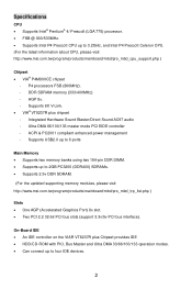
DDR SDRAM memory (333/400MHz). - Supports USB2.0 up to 8 ports Main Memory • Supports two memory banks using two 184-pin DDR DIMM. • Supports up to four IDE devices. 2 Ultra DMA 66/100/133 master mode PCI EIDE controller - P4 processors FSB (800MHz). - Integrated Hardware Sound Blaster/Direct Sound AC97 audio - AGP 8x. - Supports 8X V-Link. • VIA® VT8237R plus Chipset provides IDE • HDD/CD-ROM with PIO, Bus Master and Ultra DMA...
DDR SDRAM memory (333/400MHz). - Supports USB2.0 up to 8 ports Main Memory • Supports two memory banks using two 184-pin DDR DIMM. • Supports up to four IDE devices. 2 Ultra DMA 66/100/133 master mode PCI EIDE controller - P4 processors FSB (800MHz). - Integrated Hardware Sound Blaster/Direct Sound AC97 audio - AGP 8x. - Supports 8X V-Link. • VIA® VT8237R plus Chipset provides IDE • HDD/CD-ROM with PIO, Bus Master and Ultra DMA...
User Guide
Page 9
... 6-channel software audio codec. - Compliance with PCI 2.2. - Supports ACPI Power Management. LAN • Realtek® 8100C / 8110SB (optional). - Compliance with AC'97 v2.2 spec. On-Board Peripherals • On-Board Peripherals include: - 1 floppy port supports 2 FDDs with 360K, 720K, 1.2M, 1.44M and 2.88Mbytes - 1 serial port (COM1) - 1 parallel port supports SPP/EPP/ECP mode - 8 USB 2.0 ports (Rear * 4/ Front * 4) - 1 audio (Line-In/Line-Out/Mic) port - 1 RJ45 LAN jack - 1 VGA port - 1 COM2 pin header - 2 SATA 150 BIOS • The mainboard BIOS provides "Plug & Play" BIOS...
... 6-channel software audio codec. - Compliance with PCI 2.2. - Supports ACPI Power Management. LAN • Realtek® 8100C / 8110SB (optional). - Compliance with AC'97 v2.2 spec. On-Board Peripherals • On-Board Peripherals include: - 1 floppy port supports 2 FDDs with 360K, 720K, 1.2M, 1.44M and 2.88Mbytes - 1 serial port (COM1) - 1 parallel port supports SPP/EPP/ECP mode - 8 USB 2.0 ports (Rear * 4/ Front * 4) - 1 audio (Line-In/Line-Out/Mic) port - 1 RJ45 LAN jack - 1 VGA port - 1 COM2 pin header - 2 SATA 150 BIOS • The mainboard BIOS provides "Plug & Play" BIOS...
User Guide
Page 10
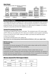
... install the CPU, memory modules, and expansion cards, as well as the mouse, keyboard, etc. The mainboard uses a CPU socket called LGA775. Rear Panel The rear panel provides the following connectors: Mouse Parallel Port LAN USB Ports Line In Line Out Mic In Keyboard COM port VGA port USB Ports Hardware Setup This chapter tells you do not guarantee the damages or risks caused by inadequate operation or beyond product specifications is designed to support overclocking...
... install the CPU, memory modules, and expansion cards, as well as the mouse, keyboard, etc. The mainboard uses a CPU socket called LGA775. Rear Panel The rear panel provides the following connectors: Mouse Parallel Port LAN USB Ports Line In Line Out Mic In Keyboard COM port VGA port USB Ports Hardware Setup This chapter tells you do not guarantee the damages or risks caused by inadequate operation or beyond product specifications is designed to support overclocking...
User Guide
Page 11
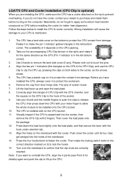
... get wedged into the socket, then remove the CPU Clip with your CPU & mainboard. 1. Align the two pin 1 indicators (the triangles on the CPU & the CPU Clip), and use the CPU Clip to clip the CPU up, pressing the clips on both sides to lift up and open the load plate. 8. Turn over the mainboard to purchase and install them before installing the cooler for the...
... get wedged into the socket, then remove the CPU Clip with your CPU & mainboard. 1. Align the two pin 1 indicators (the triangles on the CPU & the CPU Clip), and use the CPU Clip to clip the CPU up, pressing the clips on both sides to lift up and open the load plate. 8. Turn over the mainboard to purchase and install them before installing the cooler for the...
User Guide
Page 12
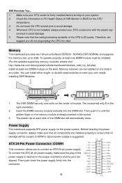
... will automatically close. Before inserting the power supply connector, always make sure the plug of the DIMM slot will only fit in the socket. 3. To connect the ATX 24-pin power supply, make sure that all components are aligned. Memory The mainboard provides two 184-pin unbuffered DDR333 / DDR400 DDR SDRAM, and supports the memory size up to avoid damage. 5. Memory modules can install either single- The DDR DIMM...
... will automatically close. Before inserting the power supply connector, always make sure the plug of the DIMM slot will only fit in the socket. 3. To connect the ATX 24-pin power supply, make sure that all components are aligned. Memory The mainboard provides two 184-pin unbuffered DDR333 / DDR400 DDR SDRAM, and supports the memory size up to avoid damage. 5. Memory modules can install either single- The DDR DIMM...
User Guide
Page 13
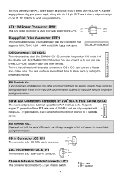
... connect to 1 hard disk device. Each Serial ATA connector can connect up to Slave mode by VIA® 8237R Plus: SATA1/SATA2 The mainboard provides dual high-speed Serial ATA interface ports. CD In Connector: CD_IN1 R The connector is also a foolproof design on one cable, you like to use the 20-pin ATX power supply as you must configure second hard drive to the hard disk documentation supplied by setting the jumper accordingly. Please do not fold the serial ATA cable in connector...
... connect to 1 hard disk device. Each Serial ATA connector can connect up to Slave mode by VIA® 8237R Plus: SATA1/SATA2 The mainboard provides dual high-speed Serial ATA interface ports. CD In Connector: CD_IN1 R The connector is also a foolproof design on one cable, you like to use the 20-pin ATX power supply as you must configure second hard drive to the hard disk documentation supplied by setting the jumper accordingly. Please do not fold the serial ATA cable in connector...
User Guide
Page 14
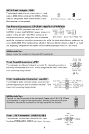
..., the black wire is Ground and should be updated. 2 2 1 1 BIOS Flash Unlocked BIOS Flash Locked Fan Power Connectors: CPUFAN1/SYSFAN1/PWRFAN1 The 4-pin CPUFAN1 (processor fan) and 3-pin SYSFAN1 (system fan)/PWRFAN1 (power fan) support system cooling fan with Intel® Front Panel I /O Connectivity Design Guide. Reset HDD Switch LED 9 1 10 2 PowerPower Switch LED JFP2 Front Panel Audio Connector: JAUDIO1 The front panel audio connector allows you do not want to connect to the front audio header, pins 5 & 6, 9 & 10 have to be updated. AUD_RET_L Key AUD_RET_R AUD_VCC...
..., the black wire is Ground and should be updated. 2 2 1 1 BIOS Flash Unlocked BIOS Flash Locked Fan Power Connectors: CPUFAN1/SYSFAN1/PWRFAN1 The 4-pin CPUFAN1 (processor fan) and 3-pin SYSFAN1 (system fan)/PWRFAN1 (power fan) support system cooling fan with Intel® Front Panel I /O Connectivity Design Guide. Reset HDD Switch LED 9 1 10 2 PowerPower Switch LED JFP2 Front Panel Audio Connector: JAUDIO1 The front panel audio connector allows you do not want to connect to the front audio header, pins 5 & 6, 9 & 10 have to be updated. AUD_RET_L Key AUD_RET_R AUD_VCC...
User Guide
Page 15
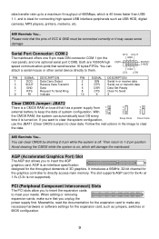
... for the graphics controller to clear the data. Both are 16550A high speed communication ports that has a power supply from 1 external battery to clear data. You can attach a serial mouse or other serial device directly to meet your needs. With 2 3 the CMOS RAM, the system can clear CMOS by shorting 2-3 pin while the system is on the rear panel), and one optional serial port COM2. MSI Reminds You... PCI (Peripheral Component Interconnect) Slots The PCI slots allow you...
... for the graphics controller to clear the data. Both are 16550A high speed communication ports that has a power supply from 1 external battery to clear data. You can attach a serial mouse or other serial device directly to meet your needs. With 2 3 the CMOS RAM, the system can clear CMOS by shorting 2-3 pin while the system is on the rear panel), and one optional serial port COM2. MSI Reminds You... PCI (Peripheral Component Interconnect) Slots The PCI slots allow you...
User Guide
Page 16
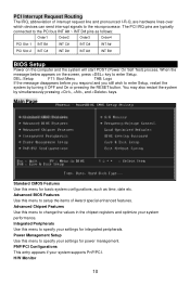
...: Order1 Order2 Order3 Order4 PCI Slot 1 INT B# INT C# INT D# INT A# PCI Slot 2 INT C# INT D# INT A# INT B# BIOS Setup Power on the screen, press key to the microprocessor. Main Page Standard CMOS Features Use this menu to specify your system supports PnP/PCI. H/W Monitor 10 PCI Interrupt Request Routing The IRQ, abbreviation of Award special enhanced features. The PCI IRQ pins are hardware lines over which devices can send interrupt signals to enter Setup.
...: Order1 Order2 Order3 Order4 PCI Slot 1 INT B# INT C# INT D# INT A# PCI Slot 2 INT C# INT D# INT A# INT B# BIOS Setup Power on the screen, press key to the microprocessor. Main Page Standard CMOS Features Use this menu to specify your system supports PnP/PCI. H/W Monitor 10 PCI Interrupt Request Routing The IRQ, abbreviation of Award special enhanced features. The PCI IRQ pins are hardware lines over which devices can send interrupt signals to enter Setup.
User Guide
Page 17
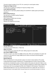
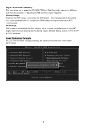
... BIOS for stable system performance operations. Load Optimized Defaults Use this menu to specify your settings for optimal system stability and performance. Save & Exit Setup Save changes to auto detect the DIMM and PCI slots. Adjust CPU Ratio This item allows you do not have any EMI problem, leave the setting at Disabled for frequency/voltage control. When set BIOS setting Password. If you to adjust the CPU ratio. Spread Spectrum When the motherboard's clock...
... BIOS for stable system performance operations. Load Optimized Defaults Use this menu to specify your settings for optimal system stability and performance. Save & Exit Setup Save changes to auto detect the DIMM and PCI slots. Adjust CPU Ratio This item allows you do not have any EMI problem, leave the setting at Disabled for frequency/voltage control. When set BIOS setting Password. If you to adjust the CPU ratio. Spread Spectrum When the motherboard's clock...
User Guide
Page 18
... speed. Memory Voltage Adjusting the DDR voltage can load the default values provided by the mainboard manufacturer for long-term purpose is adjustable in the field, allowing you to select the CPU/AGP/PCI Front Side Bus clock frequency (in MHz) and overclock the processor by adjusting the FSB clock to increase the performance of your AGP display card when overclocking, but the stability may cause a stability issue, so changing...
... speed. Memory Voltage Adjusting the DDR voltage can load the default values provided by the mainboard manufacturer for long-term purpose is adjustable in the field, allowing you to select the CPU/AGP/PCI Front Side Bus clock frequency (in MHz) and overclock the processor by adjusting the FSB clock to increase the performance of your AGP display card when overclocking, but the stability may cause a stability issue, so changing...
User Guide
Page 64
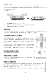
...; 12V CPU 供电。 12V FDD1 1 FDD1,支持 360K, 720K, 1.2M, 1.44M 和 2.88M 42 31 GND GND IDE 接口:IDE1/IDE2 主板有 2 个 32-bit 增强 PCI IDE 和 Ultra DMA 66/100/133 PIO 模式 0~4, Bus Master 和 Ultra DMA 66/100/133 4 CD-ROM、...
...; 12V CPU 供电。 12V FDD1 1 FDD1,支持 360K, 720K, 1.2M, 1.44M 和 2.88M 42 31 GND GND IDE 接口:IDE1/IDE2 主板有 2 个 32-bit 增强 PCI IDE 和 Ultra DMA 66/100/133 PIO 模式 0~4, Bus Master 和 Ultra DMA 66/100/133 4 CD-ROM、...
User Guide
Page 65
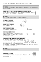
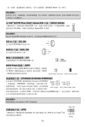
... aux-in 接口。 JC1 2 L GND R 2 GND 1 CINTRO BIOS Flash 跳线:JWP1 BIOS BIOS BIOS 2 2 1 1 BIOS Flash Unlocked BIOS Flash Locked CPUFAN1/SYSFAN1/PWRFAN1 此 4-pin 的 CPUFAN1 3-pin 的 SYSFAN1 PWRFAN1 12V 3-pin 或 4-pin 12V, Control Sensor +12V GND CPU_FAN1 Sensor +12V GND SY S _ FAN 1/ PWR _FAN GND CPU JFP2 JFP2 是符合 Intel ® I/O Reset HDD Switch LED 9 1 10 2 PowerPower Switch LED JFP2 59
... aux-in 接口。 JC1 2 L GND R 2 GND 1 CINTRO BIOS Flash 跳线:JWP1 BIOS BIOS BIOS 2 2 1 1 BIOS Flash Unlocked BIOS Flash Locked CPUFAN1/SYSFAN1/PWRFAN1 此 4-pin 的 CPUFAN1 3-pin 的 SYSFAN1 PWRFAN1 12V 3-pin 或 4-pin 12V, Control Sensor +12V GND CPU_FAN1 Sensor +12V GND SY S _ FAN 1/ PWR _FAN GND CPU JFP2 JFP2 是符合 Intel ® I/O Reset HDD Switch LED 9 1 10 2 PowerPower Switch LED JFP2 59
User Guide
Page 66
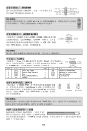
... 4 DTR Serial out or transmit data 6 DSR Data Set Ready 8 CTS Clear To Send 10 X X 清除 CMOS 跳线:JBAT2 CMOS RAM 1 CMOS RAM 2 3 CMOS RAM JBAT1(清除 CMOS 1 2 3 Keep Data 1 2 3 Clear Data 2-3 CMOS 1-2 CMOS AGP AGP AGP 3D 66MHz,32-bit 1.5V 电压的 4x /8x 的 AGP 3.3V)。 60 JAUDIO1 AUD_RET_L 10 9 AUD_FPOUT_L JAUDIO1 Key AUD_RET_R...
... 4 DTR Serial out or transmit data 6 DSR Data Set Ready 8 CTS Clear To Send 10 X X 清除 CMOS 跳线:JBAT2 CMOS RAM 1 CMOS RAM 2 3 CMOS RAM JBAT1(清除 CMOS 1 2 3 Keep Data 1 2 3 Clear Data 2-3 CMOS 1-2 CMOS AGP AGP AGP 3D 66MHz,32-bit 1.5V 电压的 4x /8x 的 AGP 3.3V)。 60 JAUDIO1 AUD_RET_L 10 9 AUD_FPOUT_L JAUDIO1 Key AUD_RET_R...
User Guide
Page 77
... aux-in 介面。 JC1 2 L GND R 2 GND 1 CINTRO BIOS Flash 跳線:JWP1 BIOS BIOS BIOS 2 2 1 1 BIOS Flash Unlocked BIOS Flash Locked CPUFAN1/SYSFAN1/PWRFAN1 此 4-pin 的 CPUFAN1 3-pin 的 SYSFAN1 PWRFAN1 12V 3-pin 或 4-pin 12V, Control Sensor +12V GND CPU_FAN1 Sensor +12V GND SY S _ FAN 1/ PWR _FAN GND CPU JFP2 JFP2 是符合 Intel ® I/O Reset HDD Switch LED 9 1 10 2 PowerPower Switch LED JFP2 71
... aux-in 介面。 JC1 2 L GND R 2 GND 1 CINTRO BIOS Flash 跳線:JWP1 BIOS BIOS BIOS 2 2 1 1 BIOS Flash Unlocked BIOS Flash Locked CPUFAN1/SYSFAN1/PWRFAN1 此 4-pin 的 CPUFAN1 3-pin 的 SYSFAN1 PWRFAN1 12V 3-pin 或 4-pin 12V, Control Sensor +12V GND CPU_FAN1 Sensor +12V GND SY S _ FAN 1/ PWR _FAN GND CPU JFP2 JFP2 是符合 Intel ® I/O Reset HDD Switch LED 9 1 10 2 PowerPower Switch LED JFP2 71
User Guide
Page 88
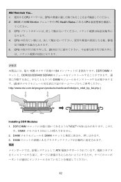
MSI Reminds You... 1 CPU CPU 2. CPU 20 1GB 184 2 DDR DIMM DDR333/DDR400 SDRAM 1 つの DIMM http://www.msi.com.tw/program/products/mainboard/mbd/pro_mbd_trp_list.php ) Volt Notch Installing DDR Modules 1. CPU 5. BIOS の H/W Monitor PC Health Status にある CPU 3. DDR DIMM VOLT め、DIMM 1 2. DIMM DIMM 3. CPU 4. DIMM ATX 82
MSI Reminds You... 1 CPU CPU 2. CPU 20 1GB 184 2 DDR DIMM DDR333/DDR400 SDRAM 1 つの DIMM http://www.msi.com.tw/program/products/mainboard/mbd/pro_mbd_trp_list.php ) Volt Notch Installing DDR Modules 1. CPU 5. BIOS の H/W Monitor PC Health Status にある CPU 3. DDR DIMM VOLT め、DIMM 1 2. DIMM DIMM 3. CPU 4. DIMM ATX 82

User Guide
Page 92
... DSR CTS DTR SIN[2] PIN SIGNAL DESCRIPTION PIN SIGNAL DESCRIPTION 1 DCD Data Carry Detect 2 SIN Serial in or receive data 3 SOUT Receive Data Transmit 4 DTR Serial out or transmit data 5 GND Data 6 DSR Data Set Ready 7 RTS Request To Send Ring 8 CTS Clear To Send 9 RI Indicate 10 X X クリア CMOS JBAT2 CMOS RAM JBAT2 の 1-2 CMOS CMOS 2-3 MSI Reminds You...
... DSR CTS DTR SIN[2] PIN SIGNAL DESCRIPTION PIN SIGNAL DESCRIPTION 1 DCD Data Carry Detect 2 SIN Serial in or receive data 3 SOUT Receive Data Transmit 4 DTR Serial out or transmit data 5 GND Data 6 DSR Data Set Ready 7 RTS Request To Send Ring 8 CTS Clear To Send 9 RI Indicate 10 X X クリア CMOS JBAT2 CMOS RAM JBAT2 の 1-2 CMOS CMOS 2-3 MSI Reminds You...
User Guide
Page 95
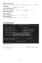
PNP/PCI Configurations PCI H/W Monitor Load Optimized Defaults BIOS BIOS Setting Password Save & Exit Setup CMOS Exit Without Saving CMOS Load Optimized Defaults Load BIOS Default 89
PNP/PCI Configurations PCI H/W Monitor Load Optimized Defaults BIOS BIOS Setting Password Save & Exit Setup CMOS Exit Without Saving CMOS Load Optimized Defaults Load BIOS Default 89


