
User Guide
Page 2
... set up the jumpers. hhSafety Precautions The following precautions should be used to connect some connectors or cables. hhHow to change without prior notice. Choose one with a magnetic head would be better. 2 Pliers, can be related with the system. ■■Disconnect the AC/DC adapter before performing any specific topic that , you are highly recommended to read this Service Manual...
... set up the jumpers. hhSafety Precautions The following precautions should be used to connect some connectors or cables. hhHow to change without prior notice. Choose one with a magnetic head would be better. 2 Pliers, can be related with the system. ■■Disconnect the AC/DC adapter before performing any specific topic that , you are highly recommended to read this Service Manual...
User Guide
Page 3
... the authorized dealer or service center for the detailed information about the product users purchased, please contact the local dealer. Please contact the manufacturer via http://www.msicomputer.com/msi_user/msi_rma/ for any upgrade or replace service. To learn more about upgrade limitation, please refer to upgrade 3 or replace any component of system disassembly only. ory, HDD, mini PCI-E card, etc. ■■...
... the authorized dealer or service center for the detailed information about the product users purchased, please contact the local dealer. Please contact the manufacturer via http://www.msicomputer.com/msi_user/msi_rma/ for any upgrade or replace service. To learn more about upgrade limitation, please refer to upgrade 3 or replace any component of system disassembly only. ory, HDD, mini PCI-E card, etc. ■■...
User Guide
Page 4
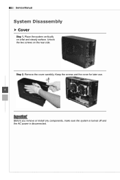
Remove the cover carefully. Place the system veritically on the rear side. Step 2. Keep the screws and the cover for later use. 2 4 1 Important Before you remove or install any components, make sure the system is turned off and the AC power is disconnected. Service Manual System Disassembly hhCover Step 1. Unlock the two screws on a flat and steady surface.
Remove the cover carefully. Place the system veritically on the rear side. Step 2. Keep the screws and the cover for later use. 2 4 1 Important Before you remove or install any components, make sure the system is turned off and the AC power is disconnected. Service Manual System Disassembly hhCover Step 1. Unlock the two screws on a flat and steady surface.
User Guide
Page 5
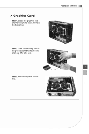
Take out the fixing plate of the graphics card bracket module, and keep it for later use. 5 Step 3. Nightblade MI Series Step 2. Place the system horizontally. Locate the graphics card and the fixing metal plate. Remove the two screws. hhGraphics Card Step 1.
Take out the fixing plate of the graphics card bracket module, and keep it for later use. 5 Step 3. Nightblade MI Series Step 2. Place the system horizontally. Locate the graphics card and the fixing metal plate. Remove the two screws. hhGraphics Card Step 1.
User Guide
Page 6
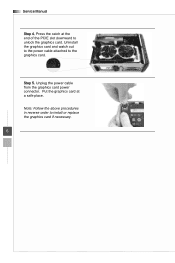
Uninstall the graphics card and watch out to the power cable attached to install or replace the graphics card if necessary. 6 Step 5. Unplug the power cable from the graphics card power connector. Note: Follow the above procedures in reverse order to the graphics card. Put the graphics card at the end of the PCIE slot downward to unlock the graphics card. Press the catch at a safe place. Service Manual Step 4.
Uninstall the graphics card and watch out to the power cable attached to install or replace the graphics card if necessary. 6 Step 5. Unplug the power cable from the graphics card power connector. Note: Follow the above procedures in reverse order to the graphics card. Put the graphics card at the end of the PCIE slot downward to unlock the graphics card. Press the catch at a safe place. Service Manual Step 4.
User Guide
Page 7
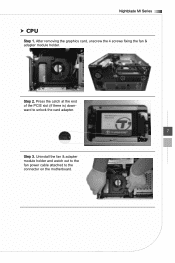
Nightblade MI Series hhCPU Step 1. After removing the graphics card, unscrew the 4 screws fixing the fan & adapter module holder. Step 2. Uninstall the fan & adapter module holder and watch out to the fan power cable attached to unlock the card adapter. 7 Step 3. Press the catch at the end of the PCIE slot (if there is) downward to the connector on the motherboard.
Nightblade MI Series hhCPU Step 1. After removing the graphics card, unscrew the 4 screws fixing the fan & adapter module holder. Step 2. Uninstall the fan & adapter module holder and watch out to the fan power cable attached to unlock the card adapter. 7 Step 3. Press the catch at the end of the PCIE slot (if there is) downward to the connector on the motherboard.
User Guide
Page 8
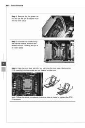
Step 5. Unscrew the screws fixing the thermal module. Note: Follow the above procedures in reverse order to install or replace the CPU if necessary. Remove the thermal module carefully and put the fan & adapter module at a save place. Remove the CPU carefully from the socket and set it at a save place. 8 Step 6. Remove the fan power cable and put it aside for later use. Service Manual Step 4. Open the load lever and lift it up, and open the load plate.
Step 5. Unscrew the screws fixing the thermal module. Note: Follow the above procedures in reverse order to install or replace the CPU if necessary. Remove the thermal module carefully and put the fan & adapter module at a save place. Remove the CPU carefully from the socket and set it at a save place. 8 Step 6. Remove the fan power cable and put it aside for later use. Service Manual Step 4. Open the load lever and lift it up, and open the load plate.
User Guide
Page 9
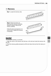
hhMemory Step 1. Follow the above procedures in place. Push the memory gently downwards until the slot clips click and lock the memory in reverse order to replace the memory if necessary. Nightblade MI Series Step 2. Flip the slot clips outwards and the memory will spring upwards instantly. Align the notch on the memory with the key on the slot and insert the memory into the slot. 2. Remove the memory carefully. Important 9 To reinstall the memory, you should: 1. Locate the memory slots.
hhMemory Step 1. Follow the above procedures in place. Push the memory gently downwards until the slot clips click and lock the memory in reverse order to replace the memory if necessary. Nightblade MI Series Step 2. Flip the slot clips outwards and the memory will spring upwards instantly. Align the notch on the memory with the key on the slot and insert the memory into the slot. 2. Remove the memory carefully. Important 9 To reinstall the memory, you should: 1. Locate the memory slots.
User Guide
Page 10
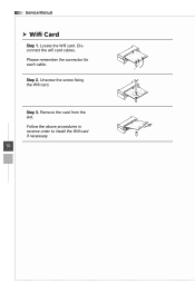
Disconnect the wifi card cables. Unscrew the screw fixing the Wifi card. Remove the card from the slot. Step 2. Step 3. Follow the above procedures in reverse order to install the Wifi card if necessary. 10 Locate the Wifi card. Please remember the connector for each cable. Service Manual hhWifi Card Step 1.
Disconnect the wifi card cables. Unscrew the screw fixing the Wifi card. Remove the card from the slot. Step 2. Step 3. Follow the above procedures in reverse order to install the Wifi card if necessary. 10 Locate the Wifi card. Please remember the connector for each cable. Service Manual hhWifi Card Step 1.
User Guide
Page 11
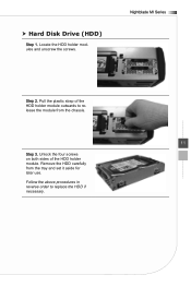
Nightblade MI Series Step 2. Pull the plastic strap of the HDD holder module. Unlock the four screws on both sides of the HDD holder module outwards to replace the HDD if necessary. Remove the HDD carefully from the chassis. 11 Step 3. Follow the above procedures in reverse order to release the module from the tray and set it aside for later use. Locate the HDD holder modules and unscrew the screws. hhHard Disk Drive (HDD) Step 1.
Nightblade MI Series Step 2. Pull the plastic strap of the HDD holder module. Unlock the four screws on both sides of the HDD holder module outwards to replace the HDD if necessary. Remove the HDD carefully from the chassis. 11 Step 3. Follow the above procedures in reverse order to release the module from the tray and set it aside for later use. Locate the HDD holder modules and unscrew the screws. hhHard Disk Drive (HDD) Step 1.
User Guide
Page 12
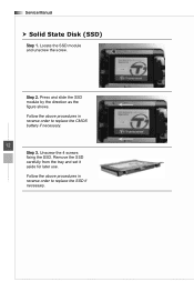
Press and slide the SSD module by the direction as the figure shows. Remove the SSD carefully from the tray and set it aside for later use. Step 2. Locate the SSD module and unscrew the screw. Follow the above procedures in reverse order to replace the CMOS battery if necessary. 12 Step 3. Service Manual hhSolid State Disk (SSD) Step 1. Follow the above procedures in reverse order to replace the SSD if necessary. Unscrew the 4 screws fixing the SSD.
Press and slide the SSD module by the direction as the figure shows. Remove the SSD carefully from the tray and set it aside for later use. Step 2. Locate the SSD module and unscrew the screw. Follow the above procedures in reverse order to replace the CMOS battery if necessary. 12 Step 3. Service Manual hhSolid State Disk (SSD) Step 1. Follow the above procedures in reverse order to replace the SSD if necessary. Unscrew the 4 screws fixing the SSD.


