
User Manual
Page 2
... iv Acquisition of Replaceable Parts iv Technical Support iv Green Product Features iv Environmental Policy v Chemical Substances Information v Battery Information v Safety Instructions vi CE Conformity viii FCC-B Radio Frequency Interference Statement viii WEEE Statement viii RoHS Statement ix Overview 1-1 ii Packing Contents 1-2 System Overview 1-3 Component Replacement & Upgrade 1-7 Getting Started 2-1 Safety & Comfort Tips 2-2 Hardware Setup 2-3 System Operations 3-1 Power Management 3-2 Network Connection (Windows 10 3-4 System Recovery (Windows 10 3-7
... iv Acquisition of Replaceable Parts iv Technical Support iv Green Product Features iv Environmental Policy v Chemical Substances Information v Battery Information v Safety Instructions vi CE Conformity viii FCC-B Radio Frequency Interference Statement viii WEEE Statement viii RoHS Statement ix Overview 1-1 ii Packing Contents 1-2 System Overview 1-3 Component Replacement & Upgrade 1-7 Getting Started 2-1 Safety & Comfort Tips 2-2 Hardware Setup 2-3 System Operations 3-1 Power Management 3-2 Network Connection (Windows 10 3-4 System Recovery (Windows 10 3-7

User Manual
Page 4
... spare parts. Technical Support If a problem arises with your system and no solution can be upgradable or replaceable by encouraging recycling ◙◙ Extended product lifetime through easy upgrades ◙◙ Reduced solid waste production through take-back policy Alternatively, please try the following help resources for technical guide, BIOS updates, driver updates and other information via http://www.msi.com/support/ for any upgrade or replace service...
... spare parts. Technical Support If a problem arises with your system and no solution can be upgradable or replaceable by encouraging recycling ◙◙ Extended product lifetime through easy upgrades ◙◙ Reduced solid waste production through take-back policy Alternatively, please try the following help resources for technical guide, BIOS updates, driver updates and other information via http://www.msi.com/support/ for any upgrade or replace service...
User Manual
Page 6
... the AC power cord before installing any add-on card or module to the equipment. ◙◙ Always disconnect the AC power cord or switch the wall socket off if the equipment would be noted. Safety Instructions ◙◙ Read the safety instructions carefully and thoroughly. ◙◙ All cautions and warnings on the equipment or user's manual should be...
... the AC power cord before installing any add-on card or module to the equipment. ◙◙ Always disconnect the AC power cord or switch the wall socket off if the equipment would be noted. Safety Instructions ◙◙ Read the safety instructions carefully and thoroughly. ◙◙ All cautions and warnings on the equipment or user's manual should be...
User Manual
Page 7
... not get it work according to step on the power cord. ◙◙ When installing the coaxial cable to the TV Tuner, it . Preface Never pour any of the following situations arises, get the equipment checked by service personnel: ◙◙ The power cord or plug is damaged. ◙◙ Liquid has penetrated into the opening that the...
... not get it work according to step on the power cord. ◙◙ When installing the coaxial cable to the TV Tuner, it . Preface Never pour any of the following situations arises, get the equipment checked by service personnel: ◙◙ The power cord or plug is damaged. ◙◙ Liquid has penetrated into the opening that the...
User Manual
Page 8
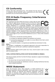
... and, if not installed and used in accordance with the instruction manual, may not cause harmful interference, and 2. This device complies with the essential safety requirements and other relevant provisions set out in compliance with Part 15 of their useful life. CE Conformity Hereby, Micro-Star International CO., LTD declares that to which the receiver is connected. ■■ Consult...
... and, if not installed and used in accordance with the instruction manual, may not cause harmful interference, and 2. This device complies with the essential safety requirements and other relevant provisions set out in compliance with Part 15 of their useful life. CE Conformity Hereby, Micro-Star International CO., LTD declares that to which the receiver is connected. ■■ Consult...
User Manual
Page 12
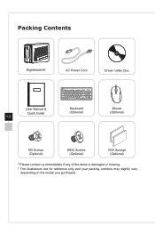
Packing Contents Nightblade MI AC Power Cord Driver/ Utility Disc User Manual & Quick Guide 1-2 Keyboard (Optional) Mouse (Optional) M3 Screws (Optional) 6#32 Screws (Optional) VGA Sponge (Optional) * Please contact us immediately if any of the items is damaged or missing. * The illustrations are for reference only and your packing contents may slightly vary depending on the model you purchased.
Packing Contents Nightblade MI AC Power Cord Driver/ Utility Disc User Manual & Quick Guide 1-2 Keyboard (Optional) Mouse (Optional) M3 Screws (Optional) 6#32 Screws (Optional) VGA Sponge (Optional) * Please contact us immediately if any of the items is damaged or missing. * The illustrations are for reference only and your packing contents may slightly vary depending on the model you purchased.

User Manual
Page 13
System Overview hh Front View Overview 1 2 3 4 1-3 1 Optical Disk Drive A DVD Super-Multi drive is integrated for your home entertainment (Blu-ray is optional). 2 Eject Button Press the eject button to open the optical disk drive. 3 Eject Hole Insert a thin, straight object (such as a paper clip) into the eject hole to open the optical disk drive manually if the eject button does not work. 4 Ventilator The ventilator on the enclosure is used for air convection and to prevent the equipment from overheating. Do not cover the ventilator.
System Overview hh Front View Overview 1 2 3 4 1-3 1 Optical Disk Drive A DVD Super-Multi drive is integrated for your home entertainment (Blu-ray is optional). 2 Eject Button Press the eject button to open the optical disk drive. 3 Eject Hole Insert a thin, straight object (such as a paper clip) into the eject hole to open the optical disk drive manually if the eject button does not work. 4 Ventilator The ventilator on the enclosure is used for air convection and to prevent the equipment from overheating. Do not cover the ventilator.
User Manual
Page 14
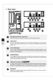
It supports up to 480Mbit/s (Hi-Speed) data transfer rate. 3 Clear CMOS Button There is CMOS RAM present on a single cable. 6 DisplayPort DisplayPort is powered by pressing DEL will be unavaiable and entering BIOS Setup by an external battery to store system booting configuration data. Therefore, you enable the "MSI Fast Boot" feature in BIOS, the keyboard will not function. This connector is for PS/2® keyboard/ mouse. 1-4 2 USB 2.0 Port The USB (Universal Serial Bus) port is used to connect a monitor with DisplayPort...
It supports up to 480Mbit/s (Hi-Speed) data transfer rate. 3 Clear CMOS Button There is CMOS RAM present on a single cable. 6 DisplayPort DisplayPort is powered by pressing DEL will be unavaiable and entering BIOS Setup by an external battery to store system booting configuration data. Therefore, you enable the "MSI Fast Boot" feature in BIOS, the keyboard will not function. This connector is for PS/2® keyboard/ mouse. 1-4 2 USB 2.0 Port The USB (Universal Serial Bus) port is used to connect a monitor with DisplayPort...
User Manual
Page 15
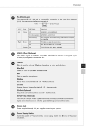
... Digital Interconnect Format) connector is provided for digital audio transmission to external speakers through an optical fiber cable. 10 Power Jack Power supplied through this switch to the Local Area Network (LAN). It supports up to your system. 11 Power Supply Switch - RS-Out Black, Rear-Surround Out in 7.1 channel mode. On (blinking) The computer is communicating with USB 2.0 devices. Yellow Green/ Orange LED Color LED State Condition Left Yellow Off LAN link is selected...
... Digital Interconnect Format) connector is provided for digital audio transmission to external speakers through an optical fiber cable. 10 Power Jack Power supplied through this switch to the Local Area Network (LAN). It supports up to your system. 11 Power Supply Switch - RS-Out Black, Rear-Surround Out in 7.1 channel mode. On (blinking) The computer is communicating with USB 2.0 devices. Yellow Green/ Orange LED Color LED State Condition Left Yellow Off LAN link is selected...

User Manual
Page 16
... system is turned off . 2 Hard Disk Drive LED This indicator shows the activity status of the HDD. It flashes when the system is accessing data on the HDD and remains off when no longer need to power on the system just to charge USB devices. 4 USB 3.0 Port (Optional) 5 Line-Out Jack This connector is provided for headphones or speakers. 6 Microphone Jack This connector is provided for microphones. 7 USB 3.0 Port (Type C) (Optional) USB Type C port is allowing...
... system is turned off . 2 Hard Disk Drive LED This indicator shows the activity status of the HDD. It flashes when the system is accessing data on the HDD and remains off when no longer need to power on the system just to charge USB devices. 4 USB 3.0 Port (Optional) 5 Line-Out Jack This connector is provided for headphones or speakers. 6 Microphone Jack This connector is provided for microphones. 7 USB 3.0 Port (Type C) (Optional) USB Type C port is allowing...
User Manual
Page 17
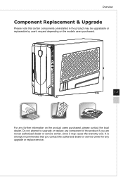
Overview Component Replacement & Upgrade Please note that you are not an authorized dealer or service center, since it may be upgradable or replaceable by user's request depending on the models users purchased. 1-7 For any upgrade or replace service. It is strongly recommended that certain components preinstalled in the product may cause the warranty void. Do not attempt to upgrade or replace any component of the product if you contact the authorized dealer or service center for any further information on the product users purchased, please contact the local dealer.
Overview Component Replacement & Upgrade Please note that you are not an authorized dealer or service center, since it may be upgradable or replaceable by user's request depending on the models users purchased. 1-7 For any upgrade or replace service. It is strongly recommended that certain components preinstalled in the product may cause the warranty void. Do not attempt to upgrade or replace any component of the product if you contact the authorized dealer or service center for any further information on the product users purchased, please contact the local dealer.

User Manual
Page 19
While connecting peripheral devices, be careful in holding the devices and use a grounded wrist strap to avoid static electricity. 2 Getting Started This chapter provides you with the information on hardware setup procedures.
While connecting peripheral devices, be careful in holding the devices and use a grounded wrist strap to avoid static electricity. 2 Getting Started This chapter provides you with the information on hardware setup procedures.

User Manual
Page 21
Connect the cables of keyboard, mouse, LAN, monitor, etc. 2-3 Getting Started Hardware Setup Important • The illustrations are for reference only. Your system may vary in appearance. • Please make sure the system has been grounded to earth through the AC power cord and the electrical outlet before powering on the system. 1.
Connect the cables of keyboard, mouse, LAN, monitor, etc. 2-3 Getting Started Hardware Setup Important • The illustrations are for reference only. Your system may vary in appearance. • Please make sure the system has been grounded to earth through the AC power cord and the electrical outlet before powering on the system. 1.

User Manual
Page 24
... power button, ■■ the network (Wake On LAN), ■■ the mouse, ■■ the keyboard. Right-click [Start] [Control Panel] from power saving mode in Windows OS allow you to initiate a low-power or "Sleep" mode after a period of user inactivity. To be able to wake up from the list and then click [System and Security]. , select Select [Power Options] and choose a power plan that suits your display, hard drive, and battery. hh Power Management through...
... power button, ■■ the network (Wake On LAN), ■■ the mouse, ■■ the keyboard. Right-click [Start] [Control Panel] from power saving mode in Windows OS allow you to initiate a low-power or "Sleep" mode after a period of user inactivity. To be able to wake up from the list and then click [System and Security]. , select Select [Power Options] and choose a power plan that suits your display, hard drive, and battery. hh Power Management through...

User Manual
Page 25
System Operations Energy Saving Tips: ■■ Turn off the monitor by pressing the monitor power button after a period of user inactivity. ■■ Tune the settings in Power Options under Windows OS to optimize your PC's power management. ■■ Install power saving software to manage your PC's energy consumption. ■■ Always disconnect the AC power cord or switch the wall socket off if your PC would be left unused for a certain time to achieve zero energy consumption. 3-3
System Operations Energy Saving Tips: ■■ Turn off the monitor by pressing the monitor power button after a period of user inactivity. ■■ Tune the settings in Power Options under Windows OS to optimize your PC's power management. ■■ Install power saving software to manage your PC's energy consumption. ■■ Always disconnect the AC power cord or switch the wall socket off if your PC would be left unused for a certain time to achieve zero energy consumption. 3-3

User Manual
Page 26
Network Connection (Windows 10) hh Wired Network 1. Select [Set up a new connection or network]. Right-click [Start] and select [Control Panel] from the list. 2. Select [View network status and tasks] under [Network and Internet]. 3-4 3.
Network Connection (Windows 10) hh Wired Network 1. Select [Set up a new connection or network]. Right-click [Start] and select [Control Panel] from the list. 2. Select [View network status and tasks] under [Network and Internet]. 3-4 3.
User Manual
Page 28
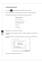
hh Wireless Network 1. To establish a new connection, select [Network and Sharing Center]. 3-6 4. Followingly, choose [Manually connect to a wireless network] and click [Next] to proceed. 7. Select [Set up . Choose a connection from the list. 3. Enter information for the wireless network you intend to add and click [Next] to continue. 6. Go to [Start] , click [Settings] and select [Network and Internet]. 2. A new WLAN connection has been made. A list of available WLAN connections pops up a new connection or network]. 5.
hh Wireless Network 1. To establish a new connection, select [Network and Sharing Center]. 3-6 4. Followingly, choose [Manually connect to a wireless network] and click [Next] to proceed. 7. Select [Set up . Choose a connection from the list. 3. Enter information for the wireless network you intend to add and click [Next] to continue. 6. Go to [Start] , click [Settings] and select [Network and Internet]. 2. A new WLAN connection has been made. A list of available WLAN connections pops up a new connection or network]. 5.
User Manual
Page 29
... to work normally. ■■ When you want to the operating system in languages. Before using the System Recovery Function may include: ■■ Restore the system back to the initial status of original manufacturer's default settings. ■■ When some errors have occurred to install the OS with other storage devices. System Operations System Recovery (Windows 10) The purposes for using the System Recovery...
... to work normally. ■■ When you want to the operating system in languages. Before using the System Recovery Function may include: ■■ Restore the system back to the initial status of original manufacturer's default settings. ■■ When some errors have occurred to install the OS with other storage devices. System Operations System Recovery (Windows 10) The purposes for using the System Recovery...

User Manual
Page 30
Reset this PC Remove everything ]. Go to start the system recovery. 3-8 3. Keep my files Reset this PC 1. Select [Recovery] and click [Get started] under [Reset this PC] to [Start] , click [Settings] and select [Update and security]. 2. Choose between [Keep my files] and [Remove everything Only the drive where Windows is installed All drives Just remove my files Remove files and clean the drive Just remove my files Remove files and clean the drive The [Choose an option] screen pops up.
Reset this PC Remove everything ]. Go to start the system recovery. 3-8 3. Keep my files Reset this PC 1. Select [Recovery] and click [Get started] under [Reset this PC] to [Start] , click [Settings] and select [Update and security]. 2. Choose between [Keep my files] and [Remove everything Only the drive where Windows is installed All drives Just remove my files Remove files and clean the drive Just remove my files Remove files and clean the drive The [Choose an option] screen pops up.

User Manual
Page 32
hh Remove everything ]. 2. Then select between [Only the drive where Windows is installed] and [All drives]. 3. If you have multiple hard drives, a screen will show the changes to choose between [Just remove my files] and [Remove files and clean the drive]. 3-10 4. The next screen will pop up, asking you to be made during the process. Select [Remove everything 1. Click [Reset] to start the system reset.
hh Remove everything ]. 2. Then select between [Only the drive where Windows is installed] and [All drives]. 3. If you have multiple hard drives, a screen will show the changes to choose between [Just remove my files] and [Remove files and clean the drive]. 3-10 4. The next screen will pop up, asking you to be made during the process. Select [Remove everything 1. Click [Reset] to start the system reset.


