
User Guide
Page 3
... resources for FAQ, technical guide, BIOS updates, driver updates, and other information: http://www.msi.com.tw/ Contact our technical staff at: support@msi.com.tw iii Visit the MSI website for further guidance. Intel® and Pentium® are registered trademarks of their respective ...® is a registered trademark of Novell, Inc. Revision History Revision V1.0 Revision History First release Date Oct. 2002 Technical Support If a problem arises with your system and no guarantee is the intellectual property of MICRO-STAR INTERNATIONAL. Copyright Notice The material in...
... resources for FAQ, technical guide, BIOS updates, driver updates, and other information: http://www.msi.com.tw/ Contact our technical staff at: support@msi.com.tw iii Visit the MSI website for further guidance. Intel® and Pentium® are registered trademarks of their respective ...® is a registered trademark of Novell, Inc. Revision History Revision V1.0 Revision History First release Date Oct. 2002 Technical Support If a problem arises with your system and no guarantee is the intellectual property of MICRO-STAR INTERNATIONAL. Copyright Notice The material in...

User Guide
Page 5
...Guide 2-2 Central Processing Unit: CPU 2-3 CPU Installation Procedures 2-4 CPU Core Speed Derivation Procedure 2-5 Memory 2-6 Memory Speed/CPU FSB Support Matrix 2-6 DIMM Module Combination 2-6 Installing DDR Modules 2-7 Power Supply 2-8 SSI 24-Pin Power Connector: POWER1 2-8 SSI 8-Pin... 2-10 USB Connectors 2-10 Serial Port Connector: COM A & COM B 2-11 v Getting Started 1-1 Mainboard Specifications 1-2 Mainboard Layout 1-5 MSI Special Features 1-6 PC Alert™ III 1-6 Live BIOS™/Live Driver 1-6 Live Monitor 1-8 Chapter 2. CONTENTS FCC-A Radio Frequency Interference ...
...Guide 2-2 Central Processing Unit: CPU 2-3 CPU Installation Procedures 2-4 CPU Core Speed Derivation Procedure 2-5 Memory 2-6 Memory Speed/CPU FSB Support Matrix 2-6 DIMM Module Combination 2-6 Installing DDR Modules 2-7 Power Supply 2-8 SSI 24-Pin Power Connector: POWER1 2-8 SSI 8-Pin... 2-10 USB Connectors 2-10 Serial Port Connector: COM A & COM B 2-11 v Getting Started 1-1 Mainboard Specifications 1-2 Mainboard Layout 1-5 MSI Special Features 1-6 PC Alert™ III 1-6 Live BIOS™/Live Driver 1-6 Live Monitor 1-8 Chapter 2. CONTENTS FCC-A Radio Frequency Interference ...

User Guide
Page 9
.... 1-2 Chipset h Intel® E7505 North Bridge - Hi-Speed USB (USB2.0) controller, 480Mb/sec. - 2 channel Ultra ATA 100 bus Master IDE controller. - PCI Master 2.2. - h 1 x 32bit/33MHz PCI slot. AC'97 2.2 interface. - 3 UHCI Host controllers and 1 EHCI Host controller. h Intel® P64H2 chipset - h 1 x mini PCI slot. MS-9121 E-ATX Mainboard Mainboard Specifications CPU h Supports single/dual Intel...
.... 1-2 Chipset h Intel® E7505 North Bridge - Hi-Speed USB (USB2.0) controller, 480Mb/sec. - 2 channel Ultra ATA 100 bus Master IDE controller. - PCI Master 2.2. - h 1 x 32bit/33MHz PCI slot. AC'97 2.2 interface. - 3 UHCI Host controllers and 1 EHCI Host controller. h Intel® P64H2 chipset - h 1 x mini PCI slot. MS-9121 E-ATX Mainboard Mainboard Specifications CPU h Supports single/dual Intel...

User Guide
Page 10
... x 2) Onboard SCSI h Integrated LSI 53C1030 Ultra320 SCSI controller. Video Add-In Card (Optional) h ATI Rage™ XL video controller with PIO, Bus Master and Ultra DMA100/66/33 operation modes. h AD 1885 software audio codec. h Mini PCI interface. h Vertical audio phonejacks (MIC, Line-In, Line-Out...) onboard. h Mini PCI interface. 1-3 h Can connect up to four IDE devices. h Supports dual channels. Getting Started Onboard IDE h An IDE controller on the ICH4 chipset provides IDE HDD/CD-ROM with 8MB memory. h 64bit/100MHz PCI...
... x 2) Onboard SCSI h Integrated LSI 53C1030 Ultra320 SCSI controller. Video Add-In Card (Optional) h ATI Rage™ XL video controller with PIO, Bus Master and Ultra DMA100/66/33 operation modes. h AD 1885 software audio codec. h Mini PCI interface. h Vertical audio phonejacks (MIC, Line-In, Line-Out...) onboard. h Mini PCI interface. 1-3 h Can connect up to four IDE devices. h Supports dual channels. Getting Started Onboard IDE h An IDE controller on the ICH4 chipset provides IDE HDD/CD-ROM with 8MB memory. h 64bit/100MHz PCI...

User Guide
Page 11
... for your mainboard specifications. Dimension h Extended ATX Form Factor: 12" x 13". h Compliant with HT Technology; *Chipset: Intel® Chipsets that support HT Technology; *BIOS: A BIOS that supports HT Technology and has it enabled; *OS: An operating system that supports HT Technology. h The mainboard provides .... MS-9121 E-ATX Mainboard BIOS h The mainboard BIOS provides "Plug & Play" BIOS which records your computer system requires ALL of the following platform Components: *CPU: Intel® Pentium® 4 or Xeon™ Processors with SSI EEB 3.0. MSI Reminds You...
... for your mainboard specifications. Dimension h Extended ATX Form Factor: 12" x 13". h Compliant with HT Technology; *Chipset: Intel® Chipsets that support HT Technology; *BIOS: A BIOS that supports HT Technology and has it enabled; *OS: An operating system that supports HT Technology. h The mainboard provides .... MS-9121 E-ATX Mainboard BIOS h The mainboard BIOS provides "Plug & Play" BIOS which records your computer system requires ALL of the following platform Components: *CPU: Intel® Pentium® 4 or Xeon™ Processors with SSI EEB 3.0. MSI Reminds You...
User Guide
Page 14
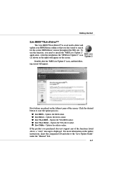
... BIOS - Updates the drivers online. Updates the VGA BIOS online. Updates the VGA driver online. If the product you purchased does not support any of the screen. Getting Started Live BIOS™/Live Driver™ The Live BIOS™/Live Driver™ is displayed. Double click the...and refer to start the update process. z Live Driver - z Live VGA Driver - z Live VGA BIOS - z Live Utility - After the installation, the "MSI Live Update 2" icon (as shown on the right) will appear: Five buttons are placed on the screen. Updates the BIOS online. Click the desired button...
... BIOS - Updates the drivers online. Updates the VGA BIOS online. Updates the VGA driver online. If the product you purchased does not support any of the screen. Getting Started Live BIOS™/Live Driver™ The Live BIOS™/Live Driver™ is displayed. Double click the...and refer to start the update process. z Live Driver - z Live VGA Driver - z Live VGA BIOS - z Live Utility - After the installation, the "MSI Live Update 2" icon (as shown on the right) will appear: Five buttons are placed on the screen. Updates the BIOS online. Click the desired button...

User Guide
Page 18
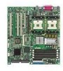
... to meet your dealer to prevent overheating. You can install SINGLE or DUAL CPUs on the computer. 2-3 Hardware Setup Central Processing Unit: CPU The mainboard supports Single/Dual Intel® Xeon™ processors and uses two CPU sockets called Socket 604 for easy CPU installation. If SINGLE CPU is intended, always...
... to meet your dealer to prevent overheating. You can install SINGLE or DUAL CPUs on the computer. 2-3 Hardware Setup Central Processing Unit: CPU The mainboard supports Single/Dual Intel® Xeon™ processors and uses two CPU sockets called Socket 604 for easy CPU installation. If SINGLE CPU is intended, always...

User Guide
Page 21
... FSB Yes 533MHz FSB No DDR266 Yes Yes DIMM Module Combination Install at least two DIMM modules on the board IN PAIRS. 2-6 Each DIMM slot supports up to 8 GB. or doublesided modules to meet your own needs, but memory modules must be installed on the slots. You can install either... single- You can install PC2100/DDR266 or PC1600/DDR200 DDR SDRAM modules on the DDR DIMM slots (DIMM 1~4). MS-9121 E-ATX Mainboard Memory The mainboard provides 4 slots for 184-pin DDR DIMM (Double InLine Memory Module) modules and supports the memory size up to a maximum size of 2GB.
... FSB Yes 533MHz FSB No DDR266 Yes Yes DIMM Module Combination Install at least two DIMM modules on the board IN PAIRS. 2-6 Each DIMM slot supports up to 8 GB. or doublesided modules to meet your own needs, but memory modules must be installed on the slots. You can install either... single- You can install PC2100/DDR266 or PC1600/DDR200 DDR SDRAM modules on the DDR DIMM slots (DIMM 1~4). MS-9121 E-ATX Mainboard Memory The mainboard provides 4 slots for 184-pin DDR DIMM (Double InLine Memory Module) modules and supports the memory size up to a maximum size of 2GB.

User Guide
Page 23
... firmly into the connector. SSI 8-Pin Power Connector: POWER2 This connector provides 12V power output to an SSI power supply. MS-9121 E-ATX Mainboard Power Supply The mainboard supports SSI power supply for the power system. SSI 24-Pin Power Connector: POWER1 This connector allows you to connect to the CPU. 24...
... firmly into the connector. SSI 8-Pin Power Connector: POWER2 This connector provides 12V power output to an SSI power supply. MS-9121 E-ATX Mainboard Power Supply The mainboard supports SSI power supply for the power system. SSI 24-Pin Power Connector: POWER1 This connector allows you to connect to the CPU. 24...

User Guide
Page 27
MS-9121 E-ATX Mainboard Parallel Port Connector: LPT1 The mainboard provides a 25-pin female centronic connector as LPT. A parallel port is a standard printer port that supports Enhanced Parallel Port (EPP) and Extended Capabilities Parallel Port (ECP) mode. 13 1 25 14 Pin Definition PIN SIGNAL DESCRIPTION 1 STROBE Strobe 2 DATA0 Data0 3 DATA1 Data1 4 DATA2 Data2 5 DATA3...
MS-9121 E-ATX Mainboard Parallel Port Connector: LPT1 The mainboard provides a 25-pin female centronic connector as LPT. A parallel port is a standard printer port that supports Enhanced Parallel Port (EPP) and Extended Capabilities Parallel Port (ECP) mode. 13 1 25 14 Pin Definition PIN SIGNAL DESCRIPTION 1 STROBE Strobe 2 DATA0 Data0 3 DATA1 Data1 4 DATA2 Data2 5 DATA3...

User Guide
Page 29
Floppy Disk Drive Connector: FDD1 The mainboard provides a standard floppy disk drive connector that supports 360K, 720K, 1.2M, 1.44M and 2.88M floppy disk types. If the chassis is connected to FDD, IDE HDD, case, modem, LAN, USB Ports, IR module ... FDD1 Chassis Intrusion Switch Connector: JCI1 This connector is opened, the switch will record this status and show a warning message on the screen. MS-9121 E-ATX Mainboard Connectors The mainboard provides connectors to connect to a 2-pin chassis switch.
Floppy Disk Drive Connector: FDD1 The mainboard provides a standard floppy disk drive connector that supports 360K, 720K, 1.2M, 1.44M and 2.88M floppy disk types. If the chassis is connected to FDD, IDE HDD, case, modem, LAN, USB Ports, IR module ... FDD1 Chassis Intrusion Switch Connector: JCI1 This connector is opened, the switch will record this status and show a warning message on the screen. MS-9121 E-ATX Mainboard Connectors The mainboard provides connectors to connect to a 2-pin chassis switch.

User Guide
Page 30
... on cable, you must configure second hard drive to Slave mode by setting its jumper. IDE2 (Secondary IDE Connector) IDE2 can connect a Master and a Slave drive. Refer to IDE1. MSI Reminds You... IDE2 IDE1 IDE1 (Primary IDE Connector) The first hard drive should always be connected to the hard disk documentation supplied... Setup Hard Disk Connectors: IDE1/2 The mainboard has a 32-bit Enhanced PCI IDE and Ultra DMA 33/66/ 100 controller that provides PIO mode 0~4, Bus Master, and Ultra DMA 33/ 66/100 function. These connectors support the provided IDE hard disk cable.
... on cable, you must configure second hard drive to Slave mode by setting its jumper. IDE2 (Secondary IDE Connector) IDE2 can connect a Master and a Slave drive. Refer to IDE1. MSI Reminds You... IDE2 IDE1 IDE1 (Primary IDE Connector) The first hard drive should always be connected to the hard disk documentation supplied... Setup Hard Disk Connectors: IDE1/2 The mainboard has a 32-bit Enhanced PCI IDE and Ultra DMA 33/66/ 100 controller that provides PIO mode 0~4, Bus Master, and Ultra DMA 33/ 66/100 function. These connectors support the provided IDE hard disk cable.

User Guide
Page 31
... SENSOR +12V GND SENSOR +12V GND CPUFAN2 SYSFAN2 SENSOR +12V GND SENSOR +12V GND SENSOR +12V GND SYSFAN5 SYSFAN4 SYSFAN3 MSI Reminds You... It supports three-pin head connector. When connecting the wire to GND. If the mainboard has a System Hardware Monitor chipset on-board, ...you must use a specially designed fan with +12V. MS-9121 E-ATX Mainboard Fan Power Connectors: CPUFAN1/2, SYSFAN1/2/3/4/5 The CPUFAN1/2 (processor fans) and SYSFAN1/2/3/4/5 (system fans) support system cooling fan with speed sensor to take note that the red wire is the positive ...
... SENSOR +12V GND SENSOR +12V GND CPUFAN2 SYSFAN2 SENSOR +12V GND SENSOR +12V GND SENSOR +12V GND SYSFAN5 SYSFAN4 SYSFAN3 MSI Reminds You... It supports three-pin head connector. When connecting the wire to GND. If the mainboard has a System Hardware Monitor chipset on-board, ...you must use a specially designed fan with +12V. MS-9121 E-ATX Mainboard Fan Power Connectors: CPUFAN1/2, SYSFAN1/2/3/4/5 The CPUFAN1/2 (processor fans) and SYSFAN1/2/3/4/5 (system fans) support system cooling fan with speed sensor to take note that the red wire is the positive ...

User Guide
Page 42
3. Push the retaining clips (on two ends of the slot) inwards until they lock onto the notches in the ends of the supporters and press it withdraws from the fixing hole. Hold the card lightly but firmly. The card should securely fit into the slot. Use long nose ...pliers to clip one on the right end and the other on the card with the supporters and press the card carefully down until it downwards until the fixing holes get locked by the...
3. Push the retaining clips (on two ends of the slot) inwards until they lock onto the notches in the ends of the supporters and press it withdraws from the fixing hole. Hold the card lightly but firmly. The card should securely fit into the slot. Use long nose ...pliers to clip one on the right end and the other on the card with the supporters and press the card carefully down until it downwards until the fixing holes get locked by the...

User Guide
Page 43
MS-9121 E-ATX Mainboard 2. Clip the other supporter and press it downwards until it withdraws from the supporters. 4. supporter 2-28 The card will automatically bound upwards after being released from the fixing hole. 3. Remove the card from the Mini PCI slot.
MS-9121 E-ATX Mainboard 2. Clip the other supporter and press it downwards until it withdraws from the supporters. 4. supporter 2-28 The card will automatically bound upwards after being released from the fixing hole. 3. Remove the card from the Mini PCI slot.

User Guide
Page 49
PC Health Status This entry shows your system supports PnP/PCI. BIOS Setup PNP/PCI Configurations This entry appears if your PC health status. Load Fail-Safe Defaults Use this menu to set user ...
PC Health Status This entry shows your system supports PnP/PCI. BIOS Setup PNP/PCI Configurations This entry appears if your PC health status. Load Fail-Safe Defaults Use this menu to set user ...

User Guide
Page 53
...; 4 or Xeon™ Processors with HT Technology; *Chipset: Intel® Chipsets that support HT Technology; *BIOS: A BIOS that supports HT Technology and has it enabled; *OS: An operating system that can support, improve reaction and response time, and increase number of boot devices where BIOS attempts to...system will boot from the CD-ROM. LAN The system will boot from the network drive. MSI Reminds You... HDD-1 The system will boot from the second HDD if available. MSI Reminds You... HDD-2 The system will boot from the third HDD if available. Available settings...
...; 4 or Xeon™ Processors with HT Technology; *Chipset: Intel® Chipsets that support HT Technology; *BIOS: A BIOS that supports HT Technology and has it enabled; *OS: An operating system that can support, improve reaction and response time, and increase number of boot devices where BIOS attempts to...system will boot from the CD-ROM. LAN The system will boot from the network drive. MSI Reminds You... HDD-1 The system will boot from the second HDD if available. MSI Reminds You... HDD-2 The system will boot from the third HDD if available. Available settings...

User Guide
Page 55
... first pressed and when the acceleration begins. Setting options: Yes, No. To find out which MPS (Multi-Processor Specification) version to select the MPS version supported by your operating system. Security Option This specifies the type of your operating system. BIOS Setup Typematic Delay (Msec) This item allows you to show...
... first pressed and when the acceleration begins. Setting options: Yes, No. To find out which MPS (Multi-Processor Specification) version to select the MPS version supported by your operating system. Security Option This specifies the type of your operating system. BIOS Setup Typematic Delay (Msec) This item allows you to show...
User Guide
Page 58
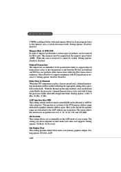
... 2X Mode, No Override. Init Display First This setting specifies which VGA card is a portion of your primary graphics adapter. MS-9121 E-ATX Mainboard C7FFFh, resulting in this field. AGP Aperture Size (MB) This setting controls just how much system RAM can perform other transactions while ...the ISA transaction is also activated to support compliance with PCI specification version 2.1. The setting you to manually set the AGP mode of the PCI memory address range dedicated to this...
... 2X Mode, No Override. Init Display First This setting specifies which VGA card is a portion of your primary graphics adapter. MS-9121 E-ATX Mainboard C7FFFh, resulting in this field. AGP Aperture Size (MB) This setting controls just how much system RAM can perform other transactions while ...the ISA transaction is also activated to support compliance with PCI specification version 2.1. The setting you to manually set the AGP mode of the PCI memory address range dedicated to this...

User Guide
Page 60
...ECP feature. It has the following message will allow the onboard parallel port to support both the ECP and EPP modes simultaneously. After selecting it, the following options... Port Mode SPP: Standard Parallel Port EPP 1.7/EPP 1.9: Enhanced Parallel Port ECP: Extended Capability Port ECP + EPP: Extended Capability Port + Enhanced Parallel Port To operate the onboard parallel port as Standard Parallel.... At this time, the user can choose between DMA channel 3 or 1. MS-9121 E-ATX Mainboard serial ports. By choosing "ECP", the onboard parallel port will reboot after a power failure...
...ECP feature. It has the following message will allow the onboard parallel port to support both the ECP and EPP modes simultaneously. After selecting it, the following options... Port Mode SPP: Standard Parallel Port EPP 1.7/EPP 1.9: Enhanced Parallel Port ECP: Extended Capability Port ECP + EPP: Extended Capability Port + Enhanced Parallel Port To operate the onboard parallel port as Standard Parallel.... At this time, the user can choose between DMA channel 3 or 1. MS-9121 E-ATX Mainboard serial ports. By choosing "ECP", the onboard parallel port will reboot after a power failure...


