User Guide
Page 5
Getting Started 1-1 Mainboard Specifications 1-2 Mainboard Layout 1-4 MSI Special Features 1-5 Fuzzy Logic™ 4 1-5 Live BIOS™/Live Driver 1-6 Live Monitor 1-7 PC Alert™ 4 1-8 Chapter 2. Hardware Setup 2-1 ...Frequency Selection through Jumpers 2-6 Memory 2-7 Introduction to DDR SDRAM 2-7 DIMM Module Combination 2-8 Installing DDR Modules 2-8 Power Supply 2-9 ATX 20-Pin Power Connector: JWR1 2-9 ATX 12V Power Connector: JPW1 2-9 v CONTENTS FCC-B Radio Frequency Interference Statement iii Copyright Notice iii Trademarks iii Revision History iii Technical ...
Getting Started 1-1 Mainboard Specifications 1-2 Mainboard Layout 1-4 MSI Special Features 1-5 Fuzzy Logic™ 4 1-5 Live BIOS™/Live Driver 1-6 Live Monitor 1-7 PC Alert™ 4 1-8 Chapter 2. Hardware Setup 2-1 ...Frequency Selection through Jumpers 2-6 Memory 2-7 Introduction to DDR SDRAM 2-7 DIMM Module Combination 2-8 Installing DDR Modules 2-8 Power Supply 2-9 ATX 20-Pin Power Connector: JWR1 2-9 ATX 12V Power Connector: JPW1 2-9 v CONTENTS FCC-B Radio Frequency Interference Statement iii Copyright Notice iii Trademarks iii Revision History iii Technical ...

User Guide
Page 8
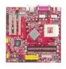
The K7N2M/K7N2GM mainboard is based on nVIDIA® nForce™2 400/IGP (Integrated Graphics Processor) & nVIDIA® nForce™2 MCP2 (Media and Communications Processor) chipsets for choosing the K7N2M/K7N2GM (MS-6777/ G) v1.X Micro ATX mainboard. Designed to fit the advanced AMD® Athlon™, Athlon™ XP or Duron™ processors, the K7N2M/K7N2GM mainboard delivers a high performance and professional desktop platform solution. 1-1 Getting Started Getting Started Thank you for optimal system efficiency. Getting Started Chapter 1.
The K7N2M/K7N2GM mainboard is based on nVIDIA® nForce™2 400/IGP (Integrated Graphics Processor) & nVIDIA® nForce™2 MCP2 (Media and Communications Processor) chipsets for choosing the K7N2M/K7N2GM (MS-6777/ G) v1.X Micro ATX mainboard. Designed to fit the advanced AMD® Athlon™, Athlon™ XP or Duron™ processors, the K7N2M/K7N2GM mainboard delivers a high performance and professional desktop platform solution. 1-1 Getting Started Getting Started Thank you for optimal system efficiency. Getting Started Chapter 1.
User Guide
Page 9
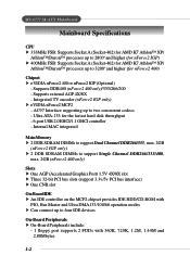
... IDE HDD/CD-ROM with 360K, 720K, 1.2M, 1.44M and 2.88Mbytes 1-2 Ultra ATA-133 for nForce2 400) Chipset h nVIDIA nForce2 400 or nForce2 IGP (Optional) - MS-6777 M-ATX Mainboard Mainboard Specifications CPU h 333MHz FSB: Supports Socket A (Socket-462) for AMD K7 Athlon™ XP/ Athlon™/Duron™ processor up to 2800+ and higher (for...
... IDE HDD/CD-ROM with 360K, 720K, 1.2M, 1.44M and 2.88Mbytes 1-2 Ultra ATA-133 for nForce2 400) Chipset h nVIDIA nForce2 400 or nForce2 IGP (Optional) - MS-6777 M-ATX Mainboard Mainboard Specifications CPU h 333MHz FSB: Supports Socket A (Socket-462) for AMD K7 Athlon™ XP/ Athlon™/Duron™ processor up to 2800+ and higher (for...
User Guide
Page 10
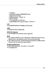
Mounting and Dimension h Micro ATX Form Factor: 24.4 cm (L) x 24.4 cm (W) h 6 mounting holes 1-3 h The mainboard provides a Desktop Management Interface (DMI) function which detects the peripheral devices and expansion cards of the board automatically. Getting Started - 1 serial port - 1 parallel port supports ... * 1/ Front * 1) LAN h RealTek RTL8201BL 10/100Mbps LAN controller Audio h Realtek ALC650 6-channel audio IEEE 1394 (Optional) h VIA PCI IEEE 1394 controller (2 ports supported) BIOS h The mainboard BIOS provides "Plug & Play" BIOS which records your...
Mounting and Dimension h Micro ATX Form Factor: 24.4 cm (L) x 24.4 cm (W) h 6 mounting holes 1-3 h The mainboard provides a Desktop Management Interface (DMI) function which detects the peripheral devices and expansion cards of the board automatically. Getting Started - 1 serial port - 1 parallel port supports ... * 1/ Front * 1) LAN h RealTek RTL8201BL 10/100Mbps LAN controller Audio h Realtek ALC650 6-channel audio IEEE 1394 (Optional) h VIA PCI IEEE 1394 controller (2 ports supported) BIOS h The mainboard BIOS provides "Plug & Play" BIOS which records your...

User Guide
Page 12
...value and then click Apply to run the setup value. 1-5 To enable the system running speed of CPU/Memory/AGP Ø MSI Info provides information about the mainboard, BIOS and OS Ø CPU Info provides detailed information about the CPU Ø CPU Fan Speed shows the current running at...default values. The CPU FSB will automatically increase the testing value until the PC reboots. shows the current CPU temperature MSI Reminds You... Features: Ø MSI Logo links to the MSI Web site Ø CPU Speed allows users to adjust the CPU speed through CPU Multiplier and FSB Ø ...
...value and then click Apply to run the setup value. 1-5 To enable the system running speed of CPU/Memory/AGP Ø MSI Info provides information about the mainboard, BIOS and OS Ø CPU Info provides detailed information about the CPU Ø CPU Fan Speed shows the current running at...default values. The CPU FSB will automatically increase the testing value until the PC reboots. shows the current CPU temperature MSI Reminds You... Features: Ø MSI Logo links to the MSI Web site Ø CPU Speed allows users to adjust the CPU speed through CPU Multiplier and FSB Ø ...
User Guide
Page 13
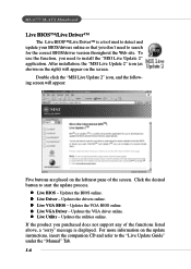
...that you need to start the update process. Updates the drivers online. Updates the VGA driver online. For more information on the screen. MS-6777 M-ATX Mainboard Live BIOS™/Live Driver™ The Live BIOS™/Live Driver™ is displayed. Click the desired button to search for the ...correct BIOS/driver version throughout the Web site. Updates the VGA BIOS online. Double click the "MSI Live Update 2" icon, and the following screen will appear on the update instructions, insert the companion CD and refer to install the...
...that you need to start the update process. Updates the drivers online. Updates the VGA driver online. For more information on the screen. MS-6777 M-ATX Mainboard Live BIOS™/Live Driver™ The Live BIOS™/Live Driver™ is displayed. Click the desired button to search for the ...correct BIOS/driver version throughout the Web site. Updates the VGA BIOS online. Double click the "MSI Live Update 2" icon, and the following screen will appear on the update instructions, insert the companion CD and refer to install the...
User Guide
Page 15
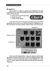
... for the system to send out a warning message. The PC Alert4 icon on the screen, with the abnormal item highlighted in the CD-ROM disk. MS-6777 M-ATX Mainboard PC Alert™ 4 The PC AlertTM 4 is abnormal, the program main screen will show the current CPU temperature. 1-8 Adjusting Keys Temperature Modes COOLER XP Users...
... for the system to send out a warning message. The PC Alert4 icon on the screen, with the abnormal item highlighted in the CD-ROM disk. MS-6777 M-ATX Mainboard PC Alert™ 4 The PC AlertTM 4 is abnormal, the program main screen will show the current CPU temperature. 1-8 Adjusting Keys Temperature Modes COOLER XP Users...

User Guide
Page 16
To do so, simply click COOLER XP and the screen will work only if your system status. 1-9 Items shown on PC Alert 4 vary depending on your mainboard supports AMD Athlon™ XP CPU. 2. Getting Started To better protect the CPU from overheating, a new feature, COOLER XP, has been added to . Cute MSI Reminds You... 1. The new feature COOLER XP will show the Cute skin (as shown below) with information about the CPU and chipset. Right-click the mouse to select the skin you want to switch to decrease the temperature of AMD Athlon XP CPU.
To do so, simply click COOLER XP and the screen will work only if your system status. 1-9 Items shown on PC Alert 4 vary depending on your mainboard supports AMD Athlon™ XP CPU. 2. Getting Started To better protect the CPU from overheating, a new feature, COOLER XP, has been added to . Cute MSI Reminds You... 1. The new feature COOLER XP will show the Cute skin (as shown below) with information about the CPU and chipset. Right-click the mouse to select the skin you want to switch to decrease the temperature of AMD Athlon XP CPU.

User Guide
Page 17
Hardware Setup Chapter 2. Hardware Setup Hardware Setup This chapter tells you how to setup the jumpers on the mainboard. While doing the installation, be careful in holding the components and follow the installation procedures. 2-1 Also, it provides the instructions on connecting the peripheral devices, such as how to install the CPU, memory modules, and expansion cards, as well as the mouse, keyboard, etc.
Hardware Setup Chapter 2. Hardware Setup Hardware Setup This chapter tells you how to setup the jumpers on the mainboard. While doing the installation, be careful in holding the components and follow the installation procedures. 2-1 Also, it provides the instructions on connecting the peripheral devices, such as how to install the CPU, memory modules, and expansion cards, as well as the mouse, keyboard, etc.

User Guide
Page 19
... and cooling fan, contact your dealer to reliable operation. Hardware Setup Central Processing Unit: CPU The mainboard supports AMD® Athlon™, Athlon™ XP and Duron™ processors in the specified thermal requirements. The mainboard uses a CPU socket called Socket A for CPU As processor technology pushes to faster speeds and higher...
... and cooling fan, contact your dealer to reliable operation. Hardware Setup Central Processing Unit: CPU The mainboard supports AMD® Athlon™, Athlon™ XP and Duron™ processors in the specified thermal requirements. The mainboard uses a CPU socket called Socket A for CPU As processor technology pushes to faster speeds and higher...
User Guide
Page 20
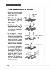
MS-6777 M-ATX Mainboard CPU Installation Procedures for the gold arrow. Pull the lever sideways away from the socket. The gold arrow should be seen. As the CPU is ... with your fingers pressing tightly on top of the correct installation procedures may cause permanent damages to move while the lever is likely to your mainboard. 5. If the CPU is properly and completely embedded into the socket. Gold arrow Gold arrow Press down firmly into the socket and can only fit...
MS-6777 M-ATX Mainboard CPU Installation Procedures for the gold arrow. Pull the lever sideways away from the socket. The gold arrow should be seen. As the CPU is ... with your fingers pressing tightly on top of the correct installation procedures may cause permanent damages to move while the lever is likely to your mainboard. 5. If the CPU is properly and completely embedded into the socket. Gold arrow Gold arrow Press down firmly into the socket and can only fit...
User Guide
Page 21
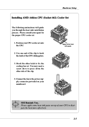
Apply some heat sink paste on top of your CPU to the power supply connector provided on your mainboard. Please apply some heat sink paste MSI Reminds You... Connect the fan to dissipate the heat more effectively. 2-5 Use one end of the clip to press down the other latch to fix ...
Apply some heat sink paste on top of your CPU to the power supply connector provided on your mainboard. Please apply some heat sink paste MSI Reminds You... Connect the fan to dissipate the heat more effectively. 2-5 Use one end of the clip to press down the other latch to fix ...
User Guide
Page 22
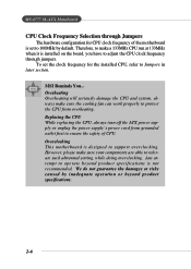
MS-6777 M-ATX Mainboard CPU Clock Frequency Selection through jumpers. Overheating Overheating will seriously damage the CPU and system, always make sure the cooling fan can work properly to protect the CPU from grounded outlet first to ensure the safety of the motherboard is not recommended. Replacing ...the CPU While replacing the CPU, always turn off the ATX power supply or unplug the power supply's power cord from overheating. Overclocking This motherboard is installed on the board, you have to support overclocking. MSI Reminds You... However, please make a 133MHz CPU run ...
MS-6777 M-ATX Mainboard CPU Clock Frequency Selection through jumpers. Overheating Overheating will seriously damage the CPU and system, always make sure the cooling fan can work properly to protect the CPU from grounded outlet first to ensure the safety of the motherboard is not recommended. Replacing ...the CPU While replacing the CPU, always turn off the ATX power supply or unplug the power supply's power cord from overheating. Overclocking This motherboard is installed on the board, you have to support overclocking. MSI Reminds You... However, please make a 133MHz CPU run ...

User Guide
Page 23
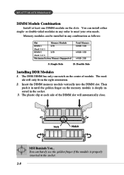
.... 2GB (nForce2 400 only) You can install DDR400 (nForce2 400 only)/333/266/200 modules on the DDR DIMM slots (DIMM 1~2). Hardware Setup Memory The mainboard provides: h 2 DDR SDRAM DIMMs to support Dual Channel DDR266/333, max. 2GB (nForce2 IGP only) h 2 DDR SDRAM DIMMs to conventional SDRAM, but doubles the rate...
.... 2GB (nForce2 400 only) You can install DDR400 (nForce2 400 only)/333/266/200 modules on the DDR DIMM slots (DIMM 1~2). Hardware Setup Memory The mainboard provides: h 2 DDR SDRAM DIMMs to support Dual Channel DDR266/333, max. 2GB (nForce2 IGP only) h 2 DDR SDRAM DIMMs to conventional SDRAM, but doubles the rate...
User Guide
Page 24
The DDR DIMM has only one DIMM module on the slots. The module will automatically close. You can be installed in the socket. 2-8 Volt Notch MSI Reminds You... MS-6777 M-ATX Mainboard DIMM Module Combination Install at each side of module. or double-sided modules in the right orientation. 2. The plastic clip at least one notch...
The DDR DIMM has only one DIMM module on the slots. The module will automatically close. You can be installed in the socket. 2-8 Volt Notch MSI Reminds You... MS-6777 M-ATX Mainboard DIMM Module Combination Install at each side of module. or double-sided modules in the right orientation. 2. The plastic clip at least one notch...

User Guide
Page 25
...make sure the plug of the mainboard. To connect to the mainboard while the JPW1 is inserted in the proper orientation and the pins are installed properly to the CPU. ATX 20-Pin Power Connector: JWR1 ATX 12V Power Connector: JPW1 The JWR1 provides power to the ATX power supply, make sure that...SIGNAL 3.3V -12V GND PS_ON GND GND GND -5V 5V 5V 2-9 Hardware Setup Power Supply The mainboard supports ATX power supply for the power system. These two connectors connect to the ATX power supply and have to work together to ensure stable operation of the power supply is used to ...
...make sure the plug of the mainboard. To connect to the mainboard while the JPW1 is inserted in the proper orientation and the pins are installed properly to the CPU. ATX 20-Pin Power Connector: JWR1 ATX 12V Power Connector: JPW1 The JWR1 provides power to the ATX power supply, make sure that...SIGNAL 3.3V -12V GND PS_ON GND GND GND -5V 5V 5V 2-9 Hardware Setup Power Supply The mainboard supports ATX power supply for the power system. These two connectors connect to the ATX power supply and have to work together to ensure stable operation of the power supply is used to ...
User Guide
Page 26
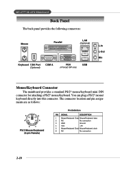
MS-6777 M-ATX Mainboard Back Panel The back panel provides the following connectors: Mouse Parallel LAN (Optional) Keyboard 1394 Port (Optional) COM A VGA (nForce2 IGP only) USB L-In L-Out Mic Mouse/Keyboard Connector The mainboard provides a standard PS/2® mouse/keyboard mini DIN connector for attaching a PS/2® mouse/keyboard. The connector location and pin assignments...
MS-6777 M-ATX Mainboard Back Panel The back panel provides the following connectors: Mouse Parallel LAN (Optional) Keyboard 1394 Port (Optional) COM A VGA (nForce2 IGP only) USB L-In L-Out Mic Mouse/Keyboard Connector The mainboard provides a standard PS/2® mouse/keyboard mini DIN connector for attaching a PS/2® mouse/keyboard. The connector location and pin assignments...

User Guide
Page 27
IEEE1394 Port USB Connectors The mainboard provides an OHCI (Open Host Controller Interface) Universal Serial Bus root for a wide range of devices, including consumer electronics audio/video (A/V) appliances, storage peripherals, other ...
IEEE1394 Port USB Connectors The mainboard provides an OHCI (Open Host Controller Interface) Universal Serial Bus root for a wide range of devices, including consumer electronics audio/video (A/V) appliances, storage peripherals, other ...

User Guide
Page 29
... pair Receive differential pair Not used Not used Receive differential pair Not used Not used for microphones. 1/8" Stereo Audio Connectors Line In Line Out Mic MSI Reminds You... Hardware Setup RJ-45 LAN Jack The mainboard provides a RJ-45 connector that allows your computer to be connected to Appendix: Using 4-
... pair Receive differential pair Not used Not used Receive differential pair Not used Not used for microphones. 1/8" Stereo Audio Connectors Line In Line Out Mic MSI Reminds You... Hardware Setup RJ-45 LAN Jack The mainboard provides a RJ-45 connector that allows your computer to be connected to Appendix: Using 4-
User Guide
Page 30
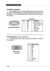
... Out or Transmit Data Data Terminal Ready) Ground Data Set Ready Request To Send Clear To Send Ring Indicate VGA Connector (nForce2 IGP only) The mainboard provides a DB 15-pin female connector to connect a VGA monitor. 5 1 15 11 VGA Connector (DB 15-pin) Pin Signal Description 1 RED 2 GREEN 3 BLUE 4 N/C 5 GND...12 SDA 13 Horizontal Sync 14 Vertical Sync 15 SCL 2-14 The port is a 16550A high speed communication port that sends/receives 16 bytes FIFOs. MS-6777 M-ATX Mainboard Serial Port Connector The mainboard offers one 9-pin male DIN connector as the serial port.
... Out or Transmit Data Data Terminal Ready) Ground Data Set Ready Request To Send Clear To Send Ring Indicate VGA Connector (nForce2 IGP only) The mainboard provides a DB 15-pin female connector to connect a VGA monitor. 5 1 15 11 VGA Connector (DB 15-pin) Pin Signal Description 1 RED 2 GREEN 3 BLUE 4 N/C 5 GND...12 SDA 13 Horizontal Sync 14 Vertical Sync 15 SCL 2-14 The port is a 16550A high speed communication port that sends/receives 16 bytes FIFOs. MS-6777 M-ATX Mainboard Serial Port Connector The mainboard offers one 9-pin male DIN connector as the serial port.


