User Guide
Page 2
... to part 15 of this equipment in a residential area is operated in accordance with FCC Standard For Home or Office Use ii Micro-Star International MS-6580 Tested to comply with the instruction manual, may cause harmful interference to radio communications. power cord, if any, must be required to correct the interference...
... to part 15 of this equipment in a residential area is operated in accordance with FCC Standard For Home or Office Use ii Micro-Star International MS-6580 Tested to comply with the instruction manual, may cause harmful interference to radio communications. power cord, if any, must be required to correct the interference...

User Guide
Page 8
Getting Started Getting Started Thank you for optimal system efficiency. Designed to fit the advanced Intel® Pentium 4/Celeron processor in the 478-pin package, the 845GE Max mainboard delivers a high performance and professional desktop platform solution. 1-1 The 845GE Max mainboard is based on Intel® 845GE & ICH4 chipsets for purchasing the 845GE Max (MS-6580 v2.X) ATX mainboard. Getting Started Chapter 1.
Getting Started Getting Started Thank you for optimal system efficiency. Designed to fit the advanced Intel® Pentium 4/Celeron processor in the 478-pin package, the 845GE Max mainboard delivers a high performance and professional desktop platform solution. 1-1 The 845GE Max mainboard is based on Intel® 845GE & ICH4 chipsets for purchasing the 845GE Max (MS-6580 v2.X) ATX mainboard. Getting Started Chapter 1.
User Guide
Page 9
MS-6580 ATX Mainboard Mainboard Specifications CPU h Supports Socket 478 for Intel® Pentium 4/Celeron processors h Core Frequency from 1.4 GHz to four IDE devices On-Board Peripherals h ... operation modes h Can connect up to 2.8 GHz and up* (*not tested yet) Chipsets h Intel® 845GE chipsets - SMBus 2.0 support - Integrated graphic controller - Integrated LAN controller Main Memory h Supports two 184-pin DDR200/DDR266/DDR333 DIMMs h Supports Max. AGP 4x slot (1.5v only) - AC'97 2.2 interface - 6 USB 2.0/1.1 ports - 2 channel Ultra ATA/100 Bus...
MS-6580 ATX Mainboard Mainboard Specifications CPU h Supports Socket 478 for Intel® Pentium 4/Celeron processors h Core Frequency from 1.4 GHz to four IDE devices On-Board Peripherals h ... operation modes h Can connect up to 2.8 GHz and up* (*not tested yet) Chipsets h Intel® 845GE chipsets - SMBus 2.0 support - Integrated graphic controller - Integrated LAN controller Main Memory h Supports two 184-pin DDR200/DDR266/DDR333 DIMMs h Supports Max. AGP 4x slot (1.5v only) - AC'97 2.2 interface - 6 USB 2.0/1.1 ports - 2 channel Ultra ATA/100 Bus...
User Guide
Page 11
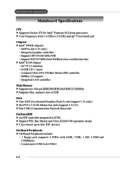
A W CD_IN1 Codec PCI Slot 1 PCI Slot 2 PCI Slot 3 PCI Slot 4 PCI Slot 5 ICH 4 BATT + IDE 1 JBAT1 IDE 2 SYS_FAN1 JSP1 JAUD1 JDB1 PCI Slot 6 CNR FDD1 JUSB1 JUSB2 JBT1 MS-6580 v2.X ATX Mainboard JFP2 JFP1 1-4 MS-6580 ATX Mainboard Mainboard Layout Top : mouse Bottom: keyboard JPW1 T:LAN jack (optional) B:USB ports CPUFAN1 ATX Power Supply Top : Game port Bottom: Line-Out Line-In Mic Intel 845GE chipset AGP Slot BIOS DDR 1 DDR 2 JIR1 W i n b o nd W 8 36 2 7 H F-
A W CD_IN1 Codec PCI Slot 1 PCI Slot 2 PCI Slot 3 PCI Slot 4 PCI Slot 5 ICH 4 BATT + IDE 1 JBAT1 IDE 2 SYS_FAN1 JSP1 JAUD1 JDB1 PCI Slot 6 CNR FDD1 JUSB1 JUSB2 JBT1 MS-6580 v2.X ATX Mainboard JFP2 JFP1 1-4 MS-6580 ATX Mainboard Mainboard Layout Top : mouse Bottom: keyboard JPW1 T:LAN jack (optional) B:USB ports CPUFAN1 ATX Power Supply Top : Game port Bottom: Line-Out Line-In Mic Intel 845GE chipset AGP Slot BIOS DDR 1 DDR 2 JIR1 W i n b o nd W 8 36 2 7 H F-
User Guide
Page 13
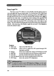
... select the desired FSB, and then click Apply to apply the new setup value. shows the current CPU temperature MSI Reminds You... If you click Turbo, click Save to start testing. MS-6580 ATX Mainboard Fuzzy Logic™ 4 The Fuzzy Logic™ 4 utility is a user friendly tool that allows ...users to adjust the voltage of CPU/Memory/AGP Ø MSI Info provides information about the mainboard, BIOS and OS Ø...
... select the desired FSB, and then click Apply to apply the new setup value. shows the current CPU temperature MSI Reminds You... If you click Turbo, click Save to start testing. MS-6580 ATX Mainboard Fuzzy Logic™ 4 The Fuzzy Logic™ 4 utility is a user friendly tool that allows ...users to adjust the voltage of CPU/Memory/AGP Ø MSI Info provides information about the mainboard, BIOS and OS Ø...
User Guide
Page 15
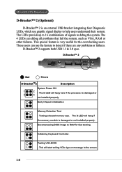
... 4 LEDs can use graphic signal display to the screen. 1-8 This special feature is very useful for fast booting. Testing onboard memory size. Testing VGA BIOS - MS-6580 ATX Mainboard D-Bracket™ 2 (Optional) D-Bracket™ 2 is an external USB bracket integrating four Diagnostic LEDs, which use the feature to detect if there are...
... 4 LEDs can use graphic signal display to the screen. 1-8 This special feature is very useful for fast booting. Testing onboard memory size. Testing VGA BIOS - MS-6580 ATX Mainboard D-Bracket™ 2 (Optional) D-Bracket™ 2 is an external USB bracket integrating four Diagnostic LEDs, which use the feature to detect if there are...
User Guide
Page 17
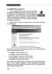
...to detect and update your BIOS/drivers online so that you need to search for the correct BIOS/driver version throughout the whole Web site. MS-6580 ATX Mainboard Live BIOS™/Live Driver™ The Live BIOS™/Live Driver™ is displayed. Updates the utilities online. After the ...installation, the "MSI Live Update Series 2" icon (as shown on the right) will appear: Five buttons are placed on the update instructions, insert the companion CD ...
...to detect and update your BIOS/drivers online so that you need to search for the correct BIOS/driver version throughout the whole Web site. MS-6580 ATX Mainboard Live BIOS™/Live Driver™ The Live BIOS™/Live Driver™ is displayed. Updates the utilities online. After the ...installation, the "MSI Live Update Series 2" icon (as shown on the right) will appear: Five buttons are placed on the update instructions, insert the companion CD ...
User Guide
Page 19
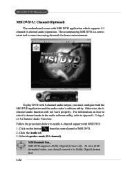
... Function. Select 6 speaker mode (5.1 channel). Follow the procedures below to Dolby Digital format first. 1-12 MS-6580 ATX Mainboard MSI DVD 5.1 Channel (Optional) The motherboard comes with 6-channel audio output, you should convert it to enable 6-channel support with MSI DVD: 1. Click on how to select 6-channel mode in the audio software utility, refer to...
... Function. Select 6 speaker mode (5.1 channel). Follow the procedures below to Dolby Digital format first. 1-12 MS-6580 ATX Mainboard MSI DVD 5.1 Channel (Optional) The motherboard comes with 6-channel audio output, you should convert it to enable 6-channel support with MSI DVD: 1. Click on how to select 6-channel mode in the audio software utility, refer to...

User Guide
Page 24
... socket. Look for Socket 478 1. Make sure to raise the lever up to move while the lever is properly and completely embedded into the socket. MS-6580 ATX Mainboard CPU Installation Procedures for the gold arrow. Sliding Plate Open Lever 90 degree 3. The gold arrow should be completely embedded into the socket...
... socket. Look for Socket 478 1. Make sure to raise the lever up to move while the lever is properly and completely embedded into the socket. MS-6580 ATX Mainboard CPU Installation Procedures for the gold arrow. Sliding Plate Open Lever 90 degree 3. The gold arrow should be completely embedded into the socket...

User Guide
Page 26
Connect the fan power cable from the mounted fan to the 3-pin fan power connector on the board. MS-6580 ATX Mainboard 5. fan power cable NOTES 2-6
Connect the fan power cable from the mounted fan to the 3-pin fan power connector on the board. MS-6580 ATX Mainboard 5. fan power cable NOTES 2-6
User Guide
Page 28
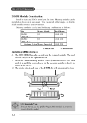
The module will automatically close. Insert the DIMM memory module vertically into the DIMM slot. or doublesided modules to meet your own needs. Volt Notch MSI Reminds You... You can be installed on the memory module is properly inserted in the socket. 2-8 Memory modules can barely see the golden finger if ... only one DIMM module on the center of the DIMM slot will only fit in any order. You can be installed in the right orientation. 2. MS-6580 ATX Mainboard DIMM Module Combination Install at each side of module.
The module will automatically close. Insert the DIMM memory module vertically into the DIMM slot. or doublesided modules to meet your own needs. Volt Notch MSI Reminds You... You can be installed on the memory module is properly inserted in the socket. 2-8 Memory modules can barely see the golden finger if ... only one DIMM module on the center of the DIMM slot will only fit in any order. You can be installed in the right orientation. 2. MS-6580 ATX Mainboard DIMM Module Combination Install at each side of module.

User Guide
Page 30
MS-6580 ATX Mainboard Back Panel The back panel provides the following connectors: Mouse LAN Parallel Midi/Joystick Keyboard USB COM A VGA L-out L-in MIC Keyboard Connector: KBMS1 The mainboard provides a standard PS/2® keyboard mini DIN connector for attaching a PS/2® keyboard. You can plug a PS/2® keyboard directly into this connector. 6 5 4 3 2 1 PS/2 Keyboard (6-pin Female) Pin Definition PIN SIGNAL DESCRIPTION 1 Keyboard DATA Keyboard DATA 2 NC No connection 3 GND Ground 4 VCC +5V 5 Keyboard Clock Keyboard clock 6 NC No connection 2-10
MS-6580 ATX Mainboard Back Panel The back panel provides the following connectors: Mouse LAN Parallel Midi/Joystick Keyboard USB COM A VGA L-out L-in MIC Keyboard Connector: KBMS1 The mainboard provides a standard PS/2® keyboard mini DIN connector for attaching a PS/2® keyboard. You can plug a PS/2® keyboard directly into this connector. 6 5 4 3 2 1 PS/2 Keyboard (6-pin Female) Pin Definition PIN SIGNAL DESCRIPTION 1 Keyboard DATA Keyboard DATA 2 NC No connection 3 GND Ground 4 VCC +5V 5 Keyboard Clock Keyboard clock 6 NC No connection 2-10

User Guide
Page 32
... pair Not used Not used Receive differential pair Not used Not used VGA Connector The mainboard provides a DB 15-pin female connector to a network environment. MS-6580 ATX Mainboard RJ-45 LAN Jack (Optional) The mainboard provides a RJ-45 connector that allows your computer to be connected to connect a VGA monitor. 5 1 15...
... pair Not used Not used Receive differential pair Not used Not used VGA Connector The mainboard provides a DB 15-pin female connector to a network environment. MS-6580 ATX Mainboard RJ-45 LAN Jack (Optional) The mainboard provides a RJ-45 connector that allows your computer to be connected to connect a VGA monitor. 5 1 15...

User Guide
Page 34
... 18 GND Ground 19 GND Ground 20 GND Ground 21 GND Ground 22 GND Ground 23 GND Ground 24 GND Ground 25 GND Ground 2-14 MS-6580 ATX Mainboard Parallel Port Connector The mainboard provides a 25-pin female centronic connector as LPT.
... 18 GND Ground 19 GND Ground 20 GND Ground 21 GND Ground 22 GND Ground 23 GND Ground 24 GND Ground 25 GND Ground 2-14 MS-6580 ATX Mainboard Parallel Port Connector The mainboard provides a 25-pin female centronic connector as LPT.

User Guide
Page 36
Floppy Disk Drive Connector: FDD1 The mainboard provides a standard floppy disk drive connector that supports 360K, 720K, 1.2M, 1.44M and 2.88M floppy disk types. 2-16 FDD1 MS-6580 ATX Mainboard Connectors The mainboard provides connectors to connect to FDD, IDE HDD, case, modem, LAN, USB Ports, IR module and CPU/System FAN.
Floppy Disk Drive Connector: FDD1 The mainboard provides a standard floppy disk drive connector that supports 360K, 720K, 1.2M, 1.44M and 2.88M floppy disk types. 2-16 FDD1 MS-6580 ATX Mainboard Connectors The mainboard provides connectors to connect to FDD, IDE HDD, case, modem, LAN, USB Ports, IR module and CPU/System FAN.
User Guide
Page 38
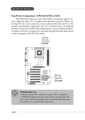
...wire to the connectors, always take advantage of the CPU fan control. CPUFAN supports the fan control. GND +12V SENSOR CPUFAN1 GND +12V SENSOR SYS_FAN1 MSI Reminds You... 1. You can install the PC Alert utility that the red wire is the positive and should be connected to the +12V, the black... wire is Ground and should be connected to GND. MS-6580 ATX Mainboard Fan Power Connectors: CPUFAN1/SYS_FAN1 The CPUFAN1 (processor fan), SYS_FAN1 (system fan) support system cooling fan with speed sensor to take note ...
...wire to the connectors, always take advantage of the CPU fan control. CPUFAN supports the fan control. GND +12V SENSOR CPUFAN1 GND +12V SENSOR SYS_FAN1 MSI Reminds You... 1. You can install the PC Alert utility that the red wire is the positive and should be connected to the +12V, the black... wire is Ground and should be connected to GND. MS-6580 ATX Mainboard Fan Power Connectors: CPUFAN1/SYS_FAN1 The CPUFAN1 (processor fan), SYS_FAN1 (system fan) support system cooling fan with speed sensor to take note ...

User Guide
Page 40
MS-6580 ATX Mainboard Front Panel Connectors: JFP1 & JFP2 The mainboard provides two front panel connectors for establishing electrical connection to GND Reserved. Do not use. JFP1 ...
MS-6580 ATX Mainboard Front Panel Connectors: JFP1 & JFP2 The mainboard provides two front panel connectors for establishing electrical connection to GND Reserved. Do not use. JFP1 ...

User Guide
Page 42
... to a maximum throughput of 480Mbps, which is 40 times faster than USB 1.1, and is ideal for users to connect to Intel® I/O Connectivity Design Guide. MS-6580 ATX Mainboard Front USB Connectors: JUSB1 & JUSB2 The mainboard provides two USB2.0 pinheaders for connecting high-speed USB interface peripherals such as USB HDD, digital...
... to a maximum throughput of 480Mbps, which is 40 times faster than USB 1.1, and is ideal for users to connect to Intel® I/O Connectivity Design Guide. MS-6580 ATX Mainboard Front USB Connectors: JUSB1 & JUSB2 The mainboard provides two USB2.0 pinheaders for connecting high-speed USB interface peripherals such as USB HDD, digital...

User Guide
Page 44
... various combinations of 16 signal combinations, please refer to JUSB1 (the USB pinheader in Chapter 1. It integrates four LEDs and allows users to DBracket™ 2. MS-6580 ATX Mainboard D-Bracket™ 2 Connector: JDB1 The mainboard comes with a JDB1 connector for red color) 9 Key 10 NC 2 10 1 9 JDB1 Connected to JDB1 D-Bracket™...
... various combinations of 16 signal combinations, please refer to JUSB1 (the USB pinheader in Chapter 1. It integrates four LEDs and allows users to DBracket™ 2. MS-6580 ATX Mainboard D-Bracket™ 2 Connector: JDB1 The mainboard comes with a JDB1 connector for red color) 9 Key 10 NC 2 10 1 9 JDB1 Connected to JDB1 D-Bracket™...
User Guide
Page 46
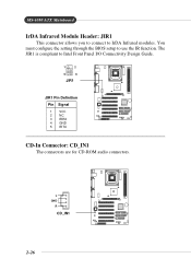
L GND R CD_IN1 2-26 MS-6580 ATX Mainboard IrDA Infrared Module Header: JIR1 This connector allows you to connect to Intel Front Panel I/O Connectivity Design Guide. 1 2 5 6 JIR1 JIR1 Pin Definition Pin Signal 1 VCC 2 NC 3 IRRX 4 GND 5 IRTX CD-In Connector: CD_IN1 The connectors are for CD-ROM audio connectors. The JIR1 is compliant to IrDA Infrared modules. You must configure the setting through the BIOS setup to use the IR function.
L GND R CD_IN1 2-26 MS-6580 ATX Mainboard IrDA Infrared Module Header: JIR1 This connector allows you to connect to Intel Front Panel I/O Connectivity Design Guide. 1 2 5 6 JIR1 JIR1 Pin Definition Pin Signal 1 VCC 2 NC 3 IRRX 4 GND 5 IRTX CD-In Connector: CD_IN1 The connectors are for CD-ROM audio connectors. The JIR1 is compliant to IrDA Infrared modules. You must configure the setting through the BIOS setup to use the IR function.


