User Manual
Page 1
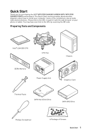
... install your phone or tablet. Some of Screws Quick Start 1 Preparing Tools and Components Intel® LGA1200 CPU CPU Fan DDR4 Memory Power Supply Unit Chassis Graphics Card Thermal Paste SATA Hard Disk Drive SATA DVD Drive Phillips Screwdriver A Package of the installations also provide video demonstrations. This Quick Start section provides demonstration diagrams about how to the URL by scanning the QR code. Quick Start Thank you for purchasing the MSI® MPG Z590 GAMING CARBON WIFI/ MPG Z590 GAMING FORCE motherboard...
... install your phone or tablet. Some of Screws Quick Start 1 Preparing Tools and Components Intel® LGA1200 CPU CPU Fan DDR4 Memory Power Supply Unit Chassis Graphics Card Thermal Paste SATA Hard Disk Drive SATA DVD Drive Phillips Screwdriver A Package of the installations also provide video demonstrations. This Quick Start section provides demonstration diagrams about how to the URL by scanning the QR code. Quick Start Thank you for purchasing the MSI® MPG Z590 GAMING CARBON WIFI/ MPG Z590 GAMING FORCE motherboard...
User Manual
Page 13
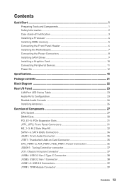
... a Processor 4 Installing DDR4 memory 5 Connecting the Front Panel Header 6 Installing the Motherboard 7 Connecting the Power Connectors 8 Installing SATA Drives 9 Installing a Graphics Card 10 Connecting Peripheral Devices 11 Power On...12 Specifications...15 Package contents 21 Block Diagram ...22 Rear I/O Panel...23 LAN Port LED Status Table 23 Audio Ports Configuration 23 Realtek Audio Console 24 Installing Antennas 26 Overview of Components 27 CPU Socket...29 DIMM Slots...30 PCI_E1~5: PCIe Expansion Slots 31 JFP1, JFP2: Front Panel Connectors 31 M2_1~3: M.2 Slots (Key...
... a Processor 4 Installing DDR4 memory 5 Connecting the Front Panel Header 6 Installing the Motherboard 7 Connecting the Power Connectors 8 Installing SATA Drives 9 Installing a Graphics Card 10 Connecting Peripheral Devices 11 Power On...12 Specifications...15 Package contents 21 Block Diagram ...22 Rear I/O Panel...23 LAN Port LED Status Table 23 Audio Ports Configuration 23 Realtek Audio Console 24 Installing Antennas 26 Overview of Components 27 CPU Socket...29 DIMM Slots...30 PCI_E1~5: PCIe Expansion Slots 31 JFP1, JFP2: Front Panel Connectors 31 M2_1~3: M.2 Slots (Key...
User Manual
Page 14
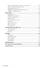
... LED connectors 43 JCORSAIR1: CORSAIR Connector 44 Onboard LEDs...45 EZ Debug LED...45 JPWRLED1: LED power input 45 LED_SW1: EZ LED Control 46 Debug Code LED...46 Hexadecimal Character Table 46 Boot Phases...46 Debug Code LED Table 47 ACPI States Codes 51 CPU Temperature 51 Installing OS, Drivers & MSI Center 52 Installing Windows® 10 52 Installing Drivers 52 MSI Center...52 UEFI BIOS...53 BIOS Setup...54 Entering BIOS Setup 54 BIOS User Guide...54 Resetting BIOS...55 Updating BIOS...55 RAID Configuration 57 Intel® Optane™ Memory Configuration 58 Troubleshooting...
... LED connectors 43 JCORSAIR1: CORSAIR Connector 44 Onboard LEDs...45 EZ Debug LED...45 JPWRLED1: LED power input 45 LED_SW1: EZ LED Control 46 Debug Code LED...46 Hexadecimal Character Table 46 Boot Phases...46 Debug Code LED Table 47 ACPI States Codes 51 CPU Temperature 51 Installing OS, Drivers & MSI Center 52 Installing Windows® 10 52 Installing Drivers 52 MSI Center...52 UEFI BIOS...53 BIOS Setup...54 Entering BIOS Setup 54 BIOS User Guide...54 Resetting BIOS...55 Updating BIOS...55 RAID Configuration 57 Intel® Optane™ Memory Configuration 58 Troubleshooting...
User Manual
Page 15
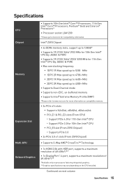
...; Processors* ∙∙Processor socket LGA1200 * Please go to www.msi.com for more information on compatible memory ∙∙3x PCIe x16 slots ▪▪Support x16/x0/x4, x8/x8/x4, x8/x4+x4/x4 ▪▪PCI_E1 & PCI_E3 slots (From CPU) ▫▫Support PCIe 4.0 for 11th Gen Intel® CPU ▫▫Support PCIe 3.0 for compatibility information. Continued on the CPU installed. Intel® Z590 Chipset ∙...
...; Processors* ∙∙Processor socket LGA1200 * Please go to www.msi.com for more information on compatible memory ∙∙3x PCIe x16 slots ▪▪Support x16/x0/x4, x8/x8/x4, x8/x4+x4/x4 ▪▪PCI_E1 & PCI_E3 slots (From CPU) ▫▫Support PCIe 4.0 for 11th Gen Intel® CPU ▫▫Support PCIe 3.0 for compatibility information. Continued on the CPU installed. Intel® Z590 Chipset ∙...
User Manual
Page 16
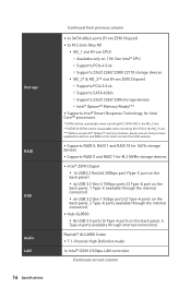
...; memory modules, please ensure that you have updated the drivers and BIOS to the latest version from MSI website. ∙∙Supports RAID 0, RAID 1 and RAID 10 for SATA storage devices ∙∙Supports RAID 0 and RAID 1 for M.2 NVMe storage devices ∙∙Intel® Z590 Chipset ▪▪1x USB3.2 Gen2x2 20Gbps port (Type-C port on the back panel) ▪▪4x USB 3.2 Gen 2 10Gbps ports (3 Type-A port on the back panel, 1 Type-C available through the internal connector) ▪▪4x USB...
...; memory modules, please ensure that you have updated the drivers and BIOS to the latest version from MSI website. ∙∙Supports RAID 0, RAID 1 and RAID 10 for SATA storage devices ∙∙Supports RAID 0 and RAID 1 for M.2 NVMe storage devices ∙∙Intel® Z590 Chipset ▪▪1x USB3.2 Gen2x2 20Gbps port (Type-C port on the back panel) ▪▪4x USB 3.2 Gen 2 10Gbps ports (3 Type-A port on the back panel, 1 Type-C available through the internal connector) ▪▪4x USB...
User Manual
Page 17
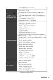
...;1x 24-pin ATX main power connector ∙∙2x 8-pin ATX 12V power connectors ∙∙1x 6-pin PCIE power connector ∙∙6x SATA 6Gb/s connectors ∙∙3x M.2 slots (M-Key) ∙∙1x USB 3.2 Gen 2 10Gbps Type-C port ∙∙1x USB 3.2 Gen 1 5Gbps connector (supports additional 2 USB 3.2 Gen 1 5Gbps ports) ∙∙2x USB 2.0 Type-A connectors (supports additional 4 USB 2.0 ports) ∙∙1x 4-pin CPU fan connector ∙∙1x 4-pin water-pump fan connector ∙∙6x 4-pin system fan connectors ∙∙1x Front panel audio...
...;1x 24-pin ATX main power connector ∙∙2x 8-pin ATX 12V power connectors ∙∙1x 6-pin PCIE power connector ∙∙6x SATA 6Gb/s connectors ∙∙3x M.2 slots (M-Key) ∙∙1x USB 3.2 Gen 2 10Gbps Type-C port ∙∙1x USB 3.2 Gen 1 5Gbps connector (supports additional 2 USB 3.2 Gen 1 5Gbps ports) ∙∙2x USB 2.0 Type-A connectors (supports additional 4 USB 2.0 ports) ∙∙1x 4-pin CPU fan connector ∙∙1x 4-pin water-pump fan connector ∙∙6x 4-pin system fan connectors ∙∙1x Front panel audio...
User Manual
Page 18
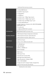
... S/PDIF OUT connector NUVOTON NCT6687 Controller Chip ∙∙CPU/ System/ Chipset temperature detection ∙∙CPU/ System/ Pump fan speed detection ∙∙CPU/ System/ Pump fan speed control ∙∙ATX Form Factor ∙∙12 in . (30.5 cm x 24.4 cm) ∙∙1x 256 Mb flash ∙∙UEFI AMI BIOS ∙∙ACPI 6.2, SMBIOS 3.0 ∙∙ Multi-language ∙∙MSI Center ∙∙MSI Sound Tune...
... S/PDIF OUT connector NUVOTON NCT6687 Controller Chip ∙∙CPU/ System/ Chipset temperature detection ∙∙CPU/ System/ Pump fan speed detection ∙∙CPU/ System/ Pump fan speed control ∙∙ATX Form Factor ∙∙12 in . (30.5 cm x 24.4 cm) ∙∙1x 256 Mb flash ∙∙UEFI AMI BIOS ∙∙ACPI 6.2, SMBIOS 3.0 ∙∙ Multi-language ∙∙MSI Center ∙∙MSI Sound Tune...
User Manual
Page 20
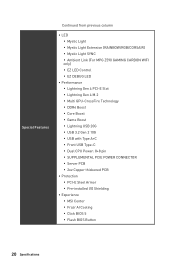
...;EZ LED Control ▪▪EZ DEBUG LED ∙∙ Performance ▪▪Lightning Gen 4 PCI-E Slot ▪▪Lightning Gen 4 M.2 ▪▪Multi GPU-CrossFire Technology ▪▪DDR4 Boost ▪▪Core Boost ▪▪Game Boost ▪▪Lightning USB 20G ▪▪USB 3.2 Gen 2 10G ▪▪USB with Type A+C ▪▪Front USB Type-C ▪▪Dual CPU Power: 8+8 pin ▪▪SUPPLEMENTAL PCIE POWER CONNECTOR...
...;EZ LED Control ▪▪EZ DEBUG LED ∙∙ Performance ▪▪Lightning Gen 4 PCI-E Slot ▪▪Lightning Gen 4 M.2 ▪▪Multi GPU-CrossFire Technology ▪▪DDR4 Boost ▪▪Core Boost ▪▪Game Boost ▪▪Lightning USB 20G ▪▪USB 3.2 Gen 2 10G ▪▪USB with Type A+C ▪▪Front USB Type-C ▪▪Dual CPU Power: 8+8 pin ▪▪SUPPLEMENTAL PCIE POWER CONNECTOR...
User Manual
Page 21
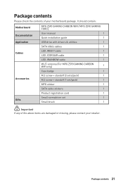
... package. It should contain: Motherboard Documentation Application Cables Accessories Gifts MPG Z590 GAMING CARBON WIFI/ MPG Z590 GAMING FORCE User manual 1 Quick installation guide 1 USB drive with drivers & utilities 1 SATA 6Gb/s cables 1 LED JRGB Y cable 1 LED JCORSAIR cable 1 LED JRAINBOW cable 1 Wi-Fi antenna (For MPG Z590 GAMING CARBON WIFI only) 1 Case badge 1 M.2 screw + standoff (2 sets/pack) 1 M.2 screw + standoff (1 set/pack) 1 MPG sticker 1 SATA cable stickers 1 Product registration card 1 Small screwdriver set 1 Small brush 1 ⚠⚠...
... package. It should contain: Motherboard Documentation Application Cables Accessories Gifts MPG Z590 GAMING CARBON WIFI/ MPG Z590 GAMING FORCE User manual 1 Quick installation guide 1 USB drive with drivers & utilities 1 SATA 6Gb/s cables 1 LED JRGB Y cable 1 LED JCORSAIR cable 1 LED JRAINBOW cable 1 Wi-Fi antenna (For MPG Z590 GAMING CARBON WIFI only) 1 Case badge 1 M.2 screw + standoff (2 sets/pack) 1 M.2 screw + standoff (1 set/pack) 1 MPG sticker 1 SATA cable stickers 1 Product registration card 1 Small screwdriver set 1 Small brush 1 ⚠⚠...

User Manual
Page 28
...JRGB1 JTBT1 JTPM1 JUSB1~2 JUSB3 JUSB4 LED_SW1 M2_1~3 PCI_E1~5 SATA1~6 Port Type Fan Connectors Power Connectors LGA1200 CPU Socket Memory slots Front Audio Connector Clear CMOS (Reset BIOS) Jumper Chassis Intrusion Connector CORSAIR Connector Tuning Controller connector Front Panel Connectors LED power input Addressable RGB LED connectors RGB LED connector Thunderbolt Add-on Card Connector TPM Module Connector USB 2.0 Connectors USB 3.2 Gen 1 Connector USB 3.2 Gen 2 Type-C Connector EZ LED Control M.2 Slots (Key M) PCIe Expansion Slots SATA 6Gb/s Connectors Page 40 36 29 30 35 41 37 44 37 31...
...JRGB1 JTBT1 JTPM1 JUSB1~2 JUSB3 JUSB4 LED_SW1 M2_1~3 PCI_E1~5 SATA1~6 Port Type Fan Connectors Power Connectors LGA1200 CPU Socket Memory slots Front Audio Connector Clear CMOS (Reset BIOS) Jumper Chassis Intrusion Connector CORSAIR Connector Tuning Controller connector Front Panel Connectors LED power input Addressable RGB LED connectors RGB LED connector Thunderbolt Add-on Card Connector TPM Module Connector USB 2.0 Connectors USB 3.2 Gen 1 Connector USB 3.2 Gen 2 Type-C Connector EZ LED Control M.2 Slots (Key M) PCIe Expansion Slots SATA 6Gb/s Connectors Page 40 36 29 30 35 41 37 44 37 31...
User Manual
Page 31
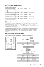
...Buzzer Speaker 1 Speaker - 2 3 Buzzer - 4 Buzzer + Speaker + Power LED Power Switch - -+ -- ++ JFP1 2 1 + 10 9 Reserved HDD LED Reset Switch 1 HDD LED + 2 3 HDD LED - 4 5 Reset Switch 6 7 Reset Switch 8 9 Reserved 10 Power LED + Power LED Power Switch Power Switch No Pin Overview of the slot. ∙∙For a single PCIe x16 expansion card installation with optimum performance, using the PCI_E1 slot is recommended. ∙∙When adding or removing expansion cards, always turn off the power supply and unplug the power supply power cable from the power...
...Buzzer Speaker 1 Speaker - 2 3 Buzzer - 4 Buzzer + Speaker + Power LED Power Switch - -+ -- ++ JFP1 2 1 + 10 9 Reserved HDD LED Reset Switch 1 HDD LED + 2 3 HDD LED - 4 5 Reset Switch 6 7 Reset Switch 8 9 Reserved 10 Power LED + Power LED Power Switch Power Switch No Pin Overview of the slot. ∙∙For a single PCIe x16 expansion card installation with optimum performance, using the PCI_E1 slot is recommended. ∙∙When adding or removing expansion cards, always turn off the power supply and unplug the power supply power cable from the power...
User Manual
Page 43
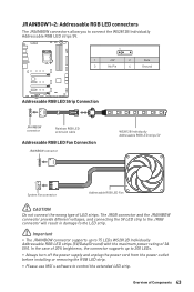
... the power supply and unplug the power cord from the power outlet before installing or removing the RGB LED strip. ∙∙Please use MSI's software to control the extended LED strip. JRAINBOW1~2: Addressable RGB LED connectors The JRAINBOW connectors allow you to connect the WS2812B Individually Addressable RGB LED strips 5V. 1 1 +5V 2 Data 3 No Pin 4 Ground Addressable RGB LED Strip Connection 1 +5V D JRAINBOW connector Rainbow RGB LED extension cable Addressable RGB LED Fan Connection JRAINBOW connector...
... the power supply and unplug the power cord from the power outlet before installing or removing the RGB LED strip. ∙∙Please use MSI's software to control the extended LED strip. JRAINBOW1~2: Addressable RGB LED connectors The JRAINBOW connectors allow you to connect the WS2812B Individually Addressable RGB LED strips 5V. 1 1 +5V 2 Data 3 No Pin 4 Ground Addressable RGB LED Strip Connection 1 +5V D JRAINBOW connector Rainbow RGB LED extension cable Addressable RGB LED Fan Connection JRAINBOW connector...
User Manual
Page 47
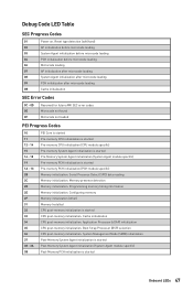
...-memory initialization. Configuring memory Memory initialization (other) Memory Installed CPU post-memory initialization is started Onboard LEDs 47 Programming memory timing information Memory initialization. Memory presence detection Memory initialization. System Management Mode (SMM) initialization Post-Memory System Agent initialization is started Post-Memory System Agent initialization (System Agent module specific) Post-Memory PCH initialization is started Pre-memory PCH initialization (PCH module specific) Memory initialization. Debug Code LED Table SEC Progress Codes 01 Power...
...-memory initialization. Configuring memory Memory initialization (other) Memory Installed CPU post-memory initialization is started Onboard LEDs 47 Programming memory timing information Memory initialization. Memory presence detection Memory initialization. System Management Mode (SMM) initialization Post-Memory System Agent initialization is started Post-Memory System Agent initialization (System Agent module specific) Post-Memory PCH initialization is started Pre-memory PCH initialization (PCH module specific) Memory initialization. Debug Code LED Table SEC Progress Codes 01 Power...
User Manual
Page 48
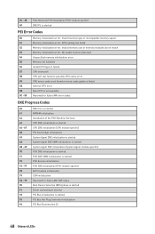
... Initialization (PCH module specific) ACPI module initialization CSM initialization Reserved for future AMI DXE codes Boot Device Selection (BDS) phase is started Driver connecting is started PCI Bus initialization is started PCI Bus Hot Plug Controller Initialization PCI Bus Enumeration 32 48 Onboard LEDs Invalid memory size or memory modules do not match Memory initialization error. SPD reading has failed Memory initialization error. 3C - 3E 4F Post-Memory PCH initialization (PCH module specific) DXE IPL is started PEI Error Codes 50 51 52...
... Initialization (PCH module specific) ACPI module initialization CSM initialization Reserved for future AMI DXE codes Boot Device Selection (BDS) phase is started Driver connecting is started PCI Bus initialization is started PCI Bus Hot Plug Controller Initialization PCI Bus Enumeration 32 48 Onboard LEDs Invalid memory size or memory modules do not match Memory initialization error. SPD reading has failed Memory initialization error. 3C - 3E 4F Post-Memory PCH initialization (PCH module specific) DXE IPL is started PEI Error Codes 50 51 52...
User Manual
Page 49
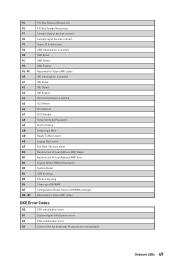
...USB initialization is started USB Reset USB Detect USB Enable Reserved for future AMI codes IDE initialization is started IDE Reset IDE Detect IDE Enable SCSI initialization is started SCSI Reset SCSI Detect SCSI Enable Setup Verifying Password Start of Setup Setup Input Wait Ready To Boot event Legacy Boot event Exit Boot Services event Runtime Set Virtual Address MAP Begin Runtime Set Virtual Address MAP End Legacy Option ROM Initialization System Reset USB hot plug PCI bus hot plug Clean-up of NVRAM Configuration Reset (reset of NVRAM settings) Reserved for future AMI codes DXE Error Codes...
...USB initialization is started USB Reset USB Detect USB Enable Reserved for future AMI codes IDE initialization is started IDE Reset IDE Detect IDE Enable SCSI initialization is started SCSI Reset SCSI Detect SCSI Enable Setup Verifying Password Start of Setup Setup Input Wait Ready To Boot event Legacy Boot event Exit Boot Services event Runtime Set Virtual Address MAP Begin Runtime Set Virtual Address MAP End Legacy Option ROM Initialization System Reset USB hot plug PCI bus hot plug Clean-up of NVRAM Configuration Reset (reset of NVRAM settings) Reserved for future AMI codes DXE Error Codes...
User Manual
Page 52
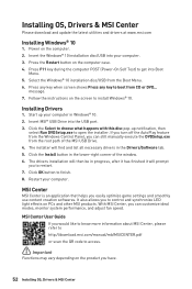
... latest utilities and drivers at www.msi.com Installing Windows® 10 1. Insert MSI® USB Drive into Boot Menu. 5. Click the Install button in the Drivers/Software tab. 5. MSI Center User Guide If you would like to know more information about MSI Center, please refer to http://download.msi.com/manual/mb/MSICENTER.pdf or scan the QR code to access. ⚠⚠Important Functions may vary depending on the screen to control and synchronize LED light...
... latest utilities and drivers at www.msi.com Installing Windows® 10 1. Insert MSI® USB Drive into Boot Menu. 5. Click the Install button in the Drivers/Software tab. 5. MSI Center User Guide If you would like to know more information about MSI Center, please refer to http://download.msi.com/manual/mb/MSICENTER.pdf or scan the QR code to access. ⚠⚠Important Functions may vary depending on the screen to control and synchronize LED light...

User Manual
Page 53
... computer. 2. When display a warning message There is compatible with a GOP/UEFI compatible graphics card or using integrated graphics from CPU for hard drive partitions larger than 2 TB. ∙∙Supports more than 4 primary partitions with the startup process. After entering the BIOS, you to enter Boot Menu message appears on your graphics card. Press Delete key, when the Press DEL key to enter Setup Menu, F11 to replace with UEFI (Unified Extensible Firmware Interface) architecture. UEFI BIOS MSI UEFI BIOS is no...
... computer. 2. When display a warning message There is compatible with a GOP/UEFI compatible graphics card or using integrated graphics from CPU for hard drive partitions larger than 2 TB. ∙∙Supports more than 4 primary partitions with the startup process. After entering the BIOS, you to enter Boot Menu message appears on your graphics card. Press Delete key, when the Press DEL key to enter Setup Menu, F11 to replace with UEFI (Unified Extensible Firmware Interface) architecture. UEFI BIOS MSI UEFI BIOS is no...
User Manual
Page 55
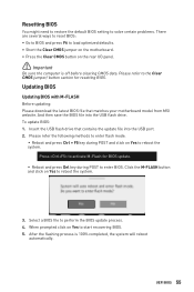
... to reset BIOS: ∙∙Go to BIOS and press F6 to load optimized defaults. ∙∙Short the Clear CMOS jumper on the motherboard. ∙∙Press the Clear CMOS button on the rear I/O panel. ⚠⚠Important Be sure the computer is 100% completed, the system will reboot automatically. Updating BIOS Updating BIOS with M-FLASH Before updating: Please download the latest BIOS file that contains the update file into the USB flash drive. After the flashing process...
... to reset BIOS: ∙∙Go to BIOS and press F6 to load optimized defaults. ∙∙Short the Clear CMOS jumper on the motherboard. ∙∙Press the Clear CMOS button on the rear I/O panel. ⚠⚠Important Be sure the computer is 100% completed, the system will reboot automatically. Updating BIOS Updating BIOS with M-FLASH Before updating: Please download the latest BIOS file that contains the update file into the USB flash drive. After the flashing process...
User Manual
Page 59
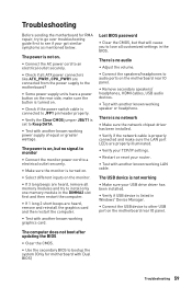
... audio ports on the monitor. ∙∙If 3 long beeps are heard, remove all customized settings in the BIOS. The computer does not boot after updating the BIOS ∙∙Clear the CMOS. ∙∙Use the secondary BIOS to lose all memory modules and try to go over troubleshooting guide first to see if your USB drive driver has been installed. ∙∙Verify if USB device is on the motherboard rear IO panel. The power...
... audio ports on the monitor. ∙∙If 3 long beeps are heard, remove all customized settings in the BIOS. The computer does not boot after updating the BIOS ∙∙Clear the CMOS. ∙∙Use the secondary BIOS to lose all memory modules and try to go over troubleshooting guide first to see if your USB drive driver has been installed. ∙∙Verify if USB device is on the motherboard rear IO panel. The power...
User Manual
Page 63
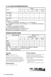
Technical Support If a problem arises with your system and no solution can be trademarks of their respective owners. All other information: http://www.msi.com yy Register your place of Micro-Star Int'l Co., Ltd. MSI reserves the right to make changes to accuracy ...technical guide, BIOS updates, driver updates, and other marks and names mentioned may be obtained from the user guide, please contact your product at: http://register.msi.com iv Regulatory Notices "超出0.1 wt 0.01 wt 2 3 PBDE Copyright Micro-Star Int'l Co.,Ltd. The MSI logo used is expressed or...
Technical Support If a problem arises with your system and no solution can be trademarks of their respective owners. All other information: http://www.msi.com yy Register your place of Micro-Star Int'l Co., Ltd. MSI reserves the right to make changes to accuracy ...technical guide, BIOS updates, driver updates, and other marks and names mentioned may be obtained from the user guide, please contact your product at: http://register.msi.com iv Regulatory Notices "超出0.1 wt 0.01 wt 2 3 PBDE Copyright Micro-Star Int'l Co.,Ltd. The MSI logo used is expressed or...


