User Manual
Page 1
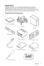
.... Please link to the URL to install your phone or tablet. Preparing Tools and Components Intel® LGA 1200 CPU CPU Fan DDR4 Memory Power Supply Unit Chassis Graphics Card Thermal Paste SATA Hard Disk Drive SATA DVD Drive Phillips Screwdriver A Package of the installations also provide video demonstrations. You may have even link to the URL by scanning the QR code. Quick Start Thank you for purchasing the MSI® MPG Z590 GAMING EDGE WIFI/ MPG Z590 GAMING PLUS motherboard.
.... Please link to the URL to install your phone or tablet. Preparing Tools and Components Intel® LGA 1200 CPU CPU Fan DDR4 Memory Power Supply Unit Chassis Graphics Card Thermal Paste SATA Hard Disk Drive SATA DVD Drive Phillips Screwdriver A Package of the installations also provide video demonstrations. You may have even link to the URL by scanning the QR code. Quick Start Thank you for purchasing the MSI® MPG Z590 GAMING EDGE WIFI/ MPG Z590 GAMING PLUS motherboard.

User Manual
Page 11
Connecting Peripheral Devices (MPG Z590 GAMING EDGE WIFI) Quick Start 11
Connecting Peripheral Devices (MPG Z590 GAMING EDGE WIFI) Quick Start 11

User Manual
Page 13
...-off notification 3 Installing a Processor 4 Installing DDR4 memory 5 Connecting the Front Panel Header 6 Installing the Motherboard 7 Connecting the Power Connectors 8 Installing SATA Drives 9 Installing a Graphics Card 10 Connecting Peripheral Devices 11 Power On...12 Specifications...15 Package contents 22 Block Diagram ...23 Rear I/O Panel...24 LAN Port LED Status Table 24 Audio Ports Configuration 24 Realtek Audio Console 25 Installing Antennas (For MPG Z590 GAMING EDGE WIFI only 27 Overview of Components 28 CPU Socket...30 DIMM Slots...31 PCI_E1~5: PCIe Expansion Slots 32...
...-off notification 3 Installing a Processor 4 Installing DDR4 memory 5 Connecting the Front Panel Header 6 Installing the Motherboard 7 Connecting the Power Connectors 8 Installing SATA Drives 9 Installing a Graphics Card 10 Connecting Peripheral Devices 11 Power On...12 Specifications...15 Package contents 22 Block Diagram ...23 Rear I/O Panel...24 LAN Port LED Status Table 24 Audio Ports Configuration 24 Realtek Audio Console 25 Installing Antennas (For MPG Z590 GAMING EDGE WIFI only 27 Overview of Components 28 CPU Socket...30 DIMM Slots...31 PCI_E1~5: PCIe Expansion Slots 32...

User Manual
Page 17
... through the internal USB connectors) ▪▪4x USB 3.2 Gen 2 10Gbps ports (1 Type-C internal connector and 3 Type-A ports on the back panel) ∙∙ Hub-GL850G ▪▪6x USB 2.0 ports (2 Type-A port on the back panel and 4 ports are available through the internal connectors) LAN ∙∙1x Intel® I225-V 2.5Gbps LAN controller Wireless LAN & Bluetooth® (For MPG Z590 GAMING EDGE WIFI only) Intel® WiFi 6E AX210 ∙∙The Wireless module is pre-installed in...
... through the internal USB connectors) ▪▪4x USB 3.2 Gen 2 10Gbps ports (1 Type-C internal connector and 3 Type-A ports on the back panel) ∙∙ Hub-GL850G ▪▪6x USB 2.0 ports (2 Type-A port on the back panel and 4 ports are available through the internal connectors) LAN ∙∙1x Intel® I225-V 2.5Gbps LAN controller Wireless LAN & Bluetooth® (For MPG Z590 GAMING EDGE WIFI only) Intel® WiFi 6E AX210 ∙∙The Wireless module is pre-installed in...

User Manual
Page 18
...1x 6-pin ATX PCIE power connector ∙∙6x SATA 6Gb/s connectors ∙∙3x M.2 slots (M-Key) ∙∙1x USB 3.2 Gen 2 10Gbps Type-C port ∙∙1x USB 3.2 Gen 1 5Gbps connector (supports additional 2 USB 3.2 Gen 1 5Gbps ports) ∙∙2x USB 2.0 connectors (supports additional 4 USB 2.0 ports) ∙∙1x 4-pin CPU fan connector ∙∙1x 4-pin water-pump fan connector ∙∙6x 4-pin system fan connectors ∙∙1x Front panel audio connector ∙∙2x System panel connectors ∙∙1x Chassis Intrusion connector ∙...
...1x 6-pin ATX PCIE power connector ∙∙6x SATA 6Gb/s connectors ∙∙3x M.2 slots (M-Key) ∙∙1x USB 3.2 Gen 2 10Gbps Type-C port ∙∙1x USB 3.2 Gen 1 5Gbps connector (supports additional 2 USB 3.2 Gen 1 5Gbps ports) ∙∙2x USB 2.0 connectors (supports additional 4 USB 2.0 ports) ∙∙1x 4-pin CPU fan connector ∙∙1x 4-pin water-pump fan connector ∙∙6x 4-pin system fan connectors ∙∙1x Front panel audio connector ∙∙2x System panel connectors ∙∙1x Chassis Intrusion connector ∙...

User Manual
Page 19
...;∙MSI Sound Tune ∙∙Gaming Mode ∙∙Creator Mode ∙∙Gaming Highlight ∙∙LAN Manager ∙∙Mystic Light ∙∙Ambient Link (For MPG Z590 GAMING EDGE WIFI only) ∙∙Frozr AI Cooling ∙∙User Scenario ∙∙True Color ∙∙Live Update ∙∙ Monitor ∙∙Super Charger ∙∙Speed Up Continued on next page Specifications...
...;∙MSI Sound Tune ∙∙Gaming Mode ∙∙Creator Mode ∙∙Gaming Highlight ∙∙LAN Manager ∙∙Mystic Light ∙∙Ambient Link (For MPG Z590 GAMING EDGE WIFI only) ∙∙Frozr AI Cooling ∙∙User Scenario ∙∙True Color ∙∙Live Update ∙∙ Monitor ∙∙Super Charger ∙∙Speed Up Continued on next page Specifications...

User Manual
Page 20
... ∙∙ Audio ▪▪Audio Boost 4 ▪▪Sound Tune ∙∙ Network ▪▪2.5G LAN ▪▪LAN Manager ▪▪Intel® WiFi (For MPG Z590 GAMING EDGE WIFI only) ∙∙ Cooling ▪▪M.2 Shield Frozr ▪▪K7 thermal pad ▪▪Choke pad ▪▪Pump Fan ▪▪Smart Fan Control ∙∙ LED ▪▪Mystic Light ▪▪...
... ∙∙ Audio ▪▪Audio Boost 4 ▪▪Sound Tune ∙∙ Network ▪▪2.5G LAN ▪▪LAN Manager ▪▪Intel® WiFi (For MPG Z590 GAMING EDGE WIFI only) ∙∙ Cooling ▪▪M.2 Shield Frozr ▪▪K7 thermal pad ▪▪Choke pad ▪▪Pump Fan ▪▪Smart Fan Control ∙∙ LED ▪▪Mystic Light ▪▪...

User Manual
Page 22
It should contain: Motherboard Documentation Application Cable Accessories Gift MPG Z590 GAMING EDGE WIFI / MPG Z590 GAMING PLUS User manual 1 Quick installation guide 1 USB drive with drivers & utilities 1 SATA 6G cables (2 cables/pack) 1 LED JRGB Y cable 1 LED JRAINBOW cable 1 Wi-Fi Antenna (for MPG Z590 GAMING EDGE WIFI only) 1 Case Badge 1 M.2 screw + standoff (1 set/pack) 1 M.2 screw + standoff (2 sets/pack) 1 MPG sticker 1 SATA cable stickers 1 Product registration card 1 Small screwdriver set 1 Small brush 1 ⚠⚠Important If any of your ...
It should contain: Motherboard Documentation Application Cable Accessories Gift MPG Z590 GAMING EDGE WIFI / MPG Z590 GAMING PLUS User manual 1 Quick installation guide 1 USB drive with drivers & utilities 1 SATA 6G cables (2 cables/pack) 1 LED JRGB Y cable 1 LED JRAINBOW cable 1 Wi-Fi Antenna (for MPG Z590 GAMING EDGE WIFI only) 1 Case Badge 1 M.2 screw + standoff (1 set/pack) 1 M.2 screw + standoff (2 sets/pack) 1 MPG sticker 1 SATA cable stickers 1 Product registration card 1 Small screwdriver set 1 Small brush 1 ⚠⚠Important If any of your ...

User Manual
Page 24
... ●● Rear Speaker Out ●●● Line-In/ Side Speaker Out ● Line-Out/ Front Speaker Out Mic In (●: connected, Blank: empty) 24 Rear I /O Panel USB 3.2 Gen 1 5Gbps Type-A Wi-Fi Antenna connectors Audio Ports DisplayPort 2.5 Gbps LAN USB 2.0 Flash BIOS Button USB 3.2 Gen 2 10Gbps Type-A Optical S/PDIF-Out Flash BIOS Port USB 3.2 Gen 2x2 20Gbps Type-C (For MPG Z590 GAMING EDGE WIFI only) ∙∙ Flash BIOS Port/ Button - Rear I /O Panel Please refer to page 50 for Updating BIOS with Flash BIOS Button.
... ●● Rear Speaker Out ●●● Line-In/ Side Speaker Out ● Line-Out/ Front Speaker Out Mic In (●: connected, Blank: empty) 24 Rear I /O Panel USB 3.2 Gen 1 5Gbps Type-A Wi-Fi Antenna connectors Audio Ports DisplayPort 2.5 Gbps LAN USB 2.0 Flash BIOS Button USB 3.2 Gen 2 10Gbps Type-A Optical S/PDIF-Out Flash BIOS Port USB 3.2 Gen 2x2 20Gbps Type-C (For MPG Z590 GAMING EDGE WIFI only) ∙∙ Flash BIOS Port/ Button - Rear I /O Panel Please refer to page 50 for Updating BIOS with Flash BIOS Button.

User Manual
Page 30
... for motherboard placement. Before attempting to install a CPU heatsink. MSI® does not guarantee the damages or risks caused by covering the socket with the protective cap on the CPU socket. ∙∙When installing a CPU, always remember to overclock, please make sure the cooling fans work properly to protect the CPU from the power outlet before booting your system. ∙∙Overheating can tolerate overclocking. MSI will...
... for motherboard placement. Before attempting to install a CPU heatsink. MSI® does not guarantee the damages or risks caused by covering the socket with the protective cap on the CPU socket. ∙∙When installing a CPU, always remember to overclock, please make sure the cooling fans work properly to protect the CPU from the power outlet before booting your system. ∙∙Overheating can tolerate overclocking. MSI will...

User Manual
Page 32
... expansion card installation with optimum performance, using the PCI_E1 slot is recommended. ∙∙When adding or removing expansion cards, always turn off the power supply and unplug the power supply power cable from the power outlet. PCI_E1~5: PCIe Expansion Slots PCI_E1: PCIe 4.0 x16 (From CPU) PCI_E2: PCIe 3.0 x1 (From Z590 chipset) PCI_E3: PCIe 3.0 x4 (From Z590 chipset) PCI_E4: PCIe 3.0 x1 (From Z590 chipset) PCI_E5: PCIe 3.0 x4 (From Z590 chipset) ⚠⚠Important ∙∙If you install a large and heavy graphics card...
... expansion card installation with optimum performance, using the PCI_E1 slot is recommended. ∙∙When adding or removing expansion cards, always turn off the power supply and unplug the power supply power cable from the power outlet. PCI_E1~5: PCIe Expansion Slots PCI_E1: PCIe 4.0 x16 (From CPU) PCI_E2: PCIe 3.0 x1 (From Z590 chipset) PCI_E3: PCIe 3.0 x4 (From Z590 chipset) PCI_E4: PCIe 3.0 x1 (From Z590 chipset) PCI_E5: PCIe 3.0 x4 (From Z590 chipset) ⚠⚠Important ∙∙If you install a large and heavy graphics card...

User Manual
Page 42
Plug the power cord and Power on the motherboard to clear the CMOS memory. Use a jumper cap to default values 1. Remove the jumper cap from a battery located on the computer. 42 Overview of Components Keep Data (default) Clear CMOS/ Reset BIOS Resetting BIOS to short JBAT1 for about 5-10 seconds. 3. Power off the computer and unplug the power cord. 2. JBAT1: Clear CMOS (Reset BIOS) Jumper There is CMOS memory onboard that is external powered from JBAT1. 4. If you want to clear the system configuration, set the jumpers to save system configuration data.
Plug the power cord and Power on the motherboard to clear the CMOS memory. Use a jumper cap to default values 1. Remove the jumper cap from a battery located on the computer. 42 Overview of Components Keep Data (default) Clear CMOS/ Reset BIOS Resetting BIOS to short JBAT1 for about 5-10 seconds. 3. Power off the computer and unplug the power cord. 2. JBAT1: Clear CMOS (Reset BIOS) Jumper There is CMOS memory onboard that is external powered from JBAT1. 4. If you want to clear the system configuration, set the jumpers to save system configuration data.

User Manual
Page 44
... connector supports up to 200 LEDs. ∙∙Always turn off the power supply and unplug the power cord from the power outlet before installing or removing the RGB LED strip. ∙∙Please use MSI's software to control the extended LED strip. 44 Overview of LED strips. JRAINBOW1~2: Addressable RGB LED connectors The JRAINBOW connectors allow you to connect the WS2812B Individually Addressable RGB LED strips 5V. 1 JRAINBOW1 1 +5V 2 Data 3 No Pin...
... connector supports up to 200 LEDs. ∙∙Always turn off the power supply and unplug the power cord from the power outlet before installing or removing the RGB LED strip. ∙∙Please use MSI's software to control the extended LED strip. 44 Overview of LED strips. JRAINBOW1~2: Addressable RGB LED connectors The JRAINBOW connectors allow you to connect the WS2812B Individually Addressable RGB LED strips 5V. 1 JRAINBOW1 1 +5V 2 Data 3 No Pin...

User Manual
Page 46
... DVD... MSI Center User Guide If you can still manually execute the DVDSetup.exe from the Windows Control Panel, you can customize ideal modes, monitor system performance, and adjust fan speed. Installing OS, Drivers & MSI Center Please download and update the latest utilities and drivers at www.msi.com Installing Windows® 10 1. Insert the Windows® 10 installation disc/USB into your computer. Press the Restart button on the product you easily optimize game settings and smoothly use...
... DVD... MSI Center User Guide If you can still manually execute the DVDSetup.exe from the Windows Control Panel, you can customize ideal modes, monitor system performance, and adjust fan speed. Installing OS, Drivers & MSI Center Please download and update the latest utilities and drivers at www.msi.com Installing Windows® 10 1. Insert the Windows® 10 installation disc/USB into your computer. Press the Restart button on the product you easily optimize game settings and smoothly use...

User Manual
Page 48
... key to enter Setup Menu, F11 to enter Boot Menu message appears on setting up the BIOS, please refer to http://download.msi.com/manual/mb/Intel500BIOS.pdf or scan the QR code to confirm your system. Select between Advanced mode and EZ mode F8: Load Overclocking Profile F9: Save Overclocking Profile F10: Save Change and Reset* F12: Take a screenshot and save it provides the modification information. BIOS User Guide If you'd like to USB flash drive...
... key to enter Setup Menu, F11 to enter Boot Menu message appears on setting up the BIOS, please refer to http://download.msi.com/manual/mb/Intel500BIOS.pdf or scan the QR code to confirm your system. Select between Advanced mode and EZ mode F8: Load Overclocking Profile F9: Save Overclocking Profile F10: Save Change and Reset* F12: Take a screenshot and save it provides the modification information. BIOS User Guide If you'd like to USB flash drive...

User Manual
Page 49
... before clearing CMOS data. Updating BIOS Updating BIOS with M-FLASH Before updating: Please download the latest BIOS file that contains the update file into the USB flash drive. Insert the USB flash drive that matches your motherboard model from MSI website. Select a BIOS file to start recovering BIOS. 5. When prompted click on Yes to reboot the system. 3. Please refer the following methods to enter flash mode. ▪▪Reboot and press Ctrl + F5 key during POST to the Clear CMOS jumper/ button section for resetting BIOS. UEFI BIOS 49...
... before clearing CMOS data. Updating BIOS Updating BIOS with M-FLASH Before updating: Please download the latest BIOS file that contains the update file into the USB flash drive. Insert the USB flash drive that matches your motherboard model from MSI website. Select a BIOS file to start recovering BIOS. 5. When prompted click on Yes to reboot the system. 3. Please refer the following methods to enter flash mode. ▪▪Reboot and press Ctrl + F5 key during POST to the Clear CMOS jumper/ button section for resetting BIOS. UEFI BIOS 49...

User Manual
Page 50
... on Install button. 4. Updating BIOS with MSI Center Before updating: ∙∙Make sure the LAN driver is already installed and the internet connection is set properly. ∙∙Please close all other application software before updating the BIOS. Press the Flash BIOS Button to Support page. 2. The installation reminder will restart automatically. Updating the BIOS with Flash BIOS Button 1. Install and launch MSI Center and go to flash BIOS, and the LED starts flashing. 6. Rename the BIOS file to install CPU and memory.) 4. Plug the USB flash drive that...
... on Install button. 4. Updating BIOS with MSI Center Before updating: ∙∙Make sure the LAN driver is already installed and the internet connection is set properly. ∙∙Please close all other application software before updating the BIOS. Press the Flash BIOS Button to Support page. 2. The installation reminder will restart automatically. Updating the BIOS with Flash BIOS Button 1. Install and launch MSI Center and go to flash BIOS, and the LED starts flashing. 6. Rename the BIOS file to install CPU and memory.) 4. Plug the USB flash drive that...

User Manual
Page 53
... speakers/ headphones, HDMI cables, USB audio devices. ∙∙Test with another known working speaker or headphone. Lost BIOS password ∙∙Clear the CMOS, but no network ∙∙Make sure the network chipset driver has been installed. ∙∙Verify if the network cable is properly connected and make sure the button is turned on. ∙∙Check if the power switch cable is connected to JFP1 pin header properly. ∙∙Verify the Clear CMOS jumper JBAT1 is listed...
... speakers/ headphones, HDMI cables, USB audio devices. ∙∙Test with another known working speaker or headphone. Lost BIOS password ∙∙Clear the CMOS, but no network ∙∙Make sure the network chipset driver has been installed. ∙∙Verify if the network cable is properly connected and make sure the button is turned on. ∙∙Check if the power switch cable is connected to JFP1 pin header properly. ∙∙Verify the Clear CMOS jumper JBAT1 is listed...

User Manual
Page 55
.... Replace only with these directives is no guarantee that to which can radiate radio frequency energy and, if not installed and used in a residential installation. KC인증서 yy MPG Z590 GAMING EDGE WIFI R-R-MSI-10-7D07 10-7D07 2021 MSI/중국 yy MPG Z590 GAMING PLUS R-R-MSI-20-7D07 20-7D07 2021 MSI/중국 クラスB VCCI-B C-Tick Compliance Battery Information European Union: Batteries, battery...
.... Replace only with these directives is no guarantee that to which can radiate radio frequency energy and, if not installed and used in a residential installation. KC인증서 yy MPG Z590 GAMING EDGE WIFI R-R-MSI-10-7D07 10-7D07 2021 MSI/중국 yy MPG Z590 GAMING PLUS R-R-MSI-20-7D07 20-7D07 2021 MSI/중국 クラスB VCCI-B C-Tick Compliance Battery Information European Union: Batteries, battery...

User Manual
Page 58
... local distributor. Technical Support If a problem arises with your system and no solution can be trademarks of Micro-Star Int'l Co., Ltd. yy Visit the MSI website for further guidance. Alternatively, please try the following help resources for technical guide, BIOS updates, driver updates, and other marks and names mentioned may be obtained from the user guide, please contact your...
... local distributor. Technical Support If a problem arises with your system and no solution can be trademarks of Micro-Star Int'l Co., Ltd. yy Visit the MSI website for further guidance. Alternatively, please try the following help resources for technical guide, BIOS updates, driver updates, and other marks and names mentioned may be obtained from the user guide, please contact your...

