User Manual
Page 1
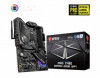
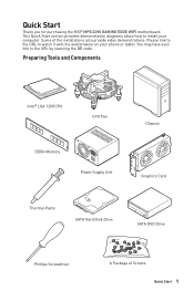
... Hard Disk Drive SATA DVD Drive Phillips Screwdriver A Package of the installations also provide video demonstrations. Some of Screws Quick Start 1 Quick Start Thank you for purchasing the MSI® MPG Z490 GAMING EDGE WIFI motherboard. This Quick Start section provides demonstration diagrams about how to install your phone or tablet. Please link to the URL to the...
... Hard Disk Drive SATA DVD Drive Phillips Screwdriver A Package of the installations also provide video demonstrations. Some of Screws Quick Start 1 Quick Start Thank you for purchasing the MSI® MPG Z490 GAMING EDGE WIFI motherboard. This Quick Start section provides demonstration diagrams about how to install your phone or tablet. Please link to the URL to the...

User Manual
Page 2
...the computer to not recognize a component or fail to start. ∙∙Hold the motherboard by the edges to avoid touching sensitive components. ∙∙It is not installed. ∙∙Before turning on the computer, ensure that there are no loose screws or metal components ...motherboard is recommended to wear an electrostatic discharge (ESD) wrist strap when handling the motherboard to damage from the power outlet before installing or removing any of the following instructions to ensure successful computer assembly. ∙∙Ensure that people can not get the ...
...the computer to not recognize a component or fail to start. ∙∙Hold the motherboard by the edges to avoid touching sensitive components. ∙∙It is not installed. ∙∙Before turning on the computer, ensure that there are no loose screws or metal components ...motherboard is recommended to wear an electrostatic discharge (ESD) wrist strap when handling the motherboard to damage from the power outlet before installing or removing any of the following instructions to ensure successful computer assembly. ∙∙Ensure that people can not get the ...

User Manual
Page 3
Installing a Processor ⚽ ⚽ https://youtu.be/4ce91YC3Oww 2 1 3 7 4 5 9 6 8 Safety Information 3
Installing a Processor ⚽ ⚽ https://youtu.be/4ce91YC3Oww 2 1 3 7 4 5 9 6 8 Safety Information 3

User Manual
Page 4
Installing DDR4 memory ⚽ ⚽ http://youtu.be/T03aDrJPyQs DIMMA2 4 Safety Information DIMMA2 DIMMB2 DIMMA1 DIMMA2 DIMMB1 DIMMB2
Installing DDR4 memory ⚽ ⚽ http://youtu.be/T03aDrJPyQs DIMMA2 4 Safety Information DIMMA2 DIMMB2 DIMMA1 DIMMA2 DIMMB1 DIMMB2
User Manual
Page 6
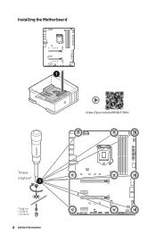
Installing the Motherboard 1 ⚽ ⚽ https://youtu.be/wWI6Qt51Wnc Torque: 3 kgf·cm* 3 *3 kgf·cm = 0.3 N·m = 2.6 lbf·in 6 Safety Information
Installing the Motherboard 1 ⚽ ⚽ https://youtu.be/wWI6Qt51Wnc Torque: 3 kgf·cm* 3 *3 kgf·cm = 0.3 N·m = 2.6 lbf·in 6 Safety Information

User Manual
Page 8
Installing SATA Drives http://youtu.be/RZsMpqxythc 2 1 3 5 4 8 Safety Information
Installing SATA Drives http://youtu.be/RZsMpqxythc 2 1 3 5 4 8 Safety Information

User Manual
Page 9
Installing a Graphics Card http://youtu.be/mG0GZpr9w_A 1 3 2 5 4 6 Safety Information 9
Installing a Graphics Card http://youtu.be/mG0GZpr9w_A 1 3 2 5 4 6 Safety Information 9
User Manual
Page 12
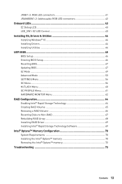
Contents Quick Start...1 Preparing Tools and Components 1 Safety Information 2 Installing a Processor 3 Installing DDR4 memory 4 Connecting the Front Panel Header 5 Installing the Motherboard 6 Connecting the Power Connectors 7 Installing SATA Drives 8 Installing a Graphics Card 9 Connecting Peripheral Devices 10 Power On...11 Specifications...14 Package contents 19 Block Diagram ...20 Rear I/O Panel...21 LAN Port LED Status Table ...
Contents Quick Start...1 Preparing Tools and Components 1 Safety Information 2 Installing a Processor 3 Installing DDR4 memory 4 Connecting the Front Panel Header 5 Installing the Motherboard 6 Connecting the Power Connectors 7 Installing SATA Drives 8 Installing a Graphics Card 9 Connecting Peripheral Devices 10 Power On...11 Specifications...14 Package contents 19 Block Diagram ...20 Rear I/O Panel...21 LAN Port LED Status Table ...
User Manual
Page 13
...RGB LED connectors 42 Onboard LEDs...43 EZ Debug LED...43 LED_SW1: EZ LED Control 43 Installing OS, Drivers & Utilities 44 Installing Windows® 10 44 Installing Drivers 44 Installing Utilities 44 UEFI BIOS...45 BIOS Setup...46 Entering BIOS Setup 46 Resetting BIOS...47 Updating ... Volume 66 Resetting Disks to Non-RAID 67 Rebuilding RAID Array 68 Installing RAID Driver 69 Installing Intel® Rapid Storage Technology Software 69 Intel® Optane™ Memory Configuration 70 System Requirements 70 Installing the Intel® Optane™ memory 70 Removing the Intel®...
...RGB LED connectors 42 Onboard LEDs...43 EZ Debug LED...43 LED_SW1: EZ LED Control 43 Installing OS, Drivers & Utilities 44 Installing Windows® 10 44 Installing Drivers 44 Installing Utilities 44 UEFI BIOS...45 BIOS Setup...46 Entering BIOS Setup 46 Resetting BIOS...47 Updating ... Volume 66 Resetting Disks to Non-RAID 67 Rebuilding RAID Array 68 Installing RAID Driver 69 Installing Intel® Rapid Storage Technology Software 69 Intel® Optane™ Memory Configuration 70 System Requirements 70 Installing the Intel® Optane™ memory 70 Removing the Intel®...
User Manual
Page 14
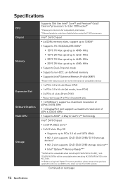
...memory ∙∙Supports Intel® Extreme Memory Profile (XMP) *Please refer www.msi.com for more information on next page 14 Specifications Continued on compatible memory ∙∙...of 4096 x 2304 @ 60Hz ∙∙Supports AMD® 2-Way CrossFire™ Technology Intel® Z490 Chipset ∙∙6x SATA 6Gb/s ports* ∙∙2x M.2 slots (Key M) ▪▪...Optane™ Memory Ready*** * SATA2 will be unavailable when installing M.2 SATA SSD in the M2_1 slot. ** SATA5 & SATA6 will be unavailable when installing M.2 SATA/PCIe SSD in the M2_2 slot. *** Before...
...memory ∙∙Supports Intel® Extreme Memory Profile (XMP) *Please refer www.msi.com for more information on next page 14 Specifications Continued on compatible memory ∙∙...of 4096 x 2304 @ 60Hz ∙∙Supports AMD® 2-Way CrossFire™ Technology Intel® Z490 Chipset ∙∙6x SATA 6Gb/s ports* ∙∙2x M.2 slots (Key M) ▪▪...Optane™ Memory Ready*** * SATA2 will be unavailable when installing M.2 SATA SSD in the M2_1 slot. ** SATA5 & SATA6 will be unavailable when installing M.2 SATA/PCIe SSD in the M2_2 slot. *** Before...
User Manual
Page 18
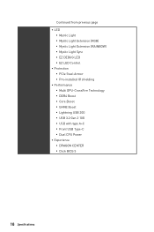
...;▪EZ LED Control ∙∙ Protection ▪▪PCIe Steel Armor ▪▪Pre-installed IO shielding ∙∙ Performance ▪▪Multi GPU-CrossFire Technology ▪▪DDR4 Boost ▪▪Core Boost ▪▪GAME Boost ▪▪Lightning USB 20G ▪▪USB 3.2 Gen 2 10G ▪▪USB...
...;▪EZ LED Control ∙∙ Protection ▪▪PCIe Steel Armor ▪▪Pre-installed IO shielding ∙∙ Performance ▪▪Multi GPU-CrossFire Technology ▪▪DDR4 Boost ▪▪Core Boost ▪▪GAME Boost ▪▪Lightning USB 20G ▪▪USB 3.2 Gen 2 10G ▪▪USB...
User Manual
Page 19
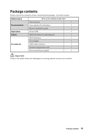
Package contents 19 It should contain: Motherboard Documentation Application Cables Accessories MPG Z490 GAMING EDGE WIFI User manual 1 Case stand-off notification 1 Quick installation guide 1 Driver DVD 1 SATA 6G cables (2 cables/pack) 1 Wi-Fi Antenna 1 Case badge 1 SATA cable stickers 1 Product registration card 1 M.2 screws (3 pcs./pack) 1 ⚠⚠Important If any of your retailer. Package contents Please check the contents of the above items are damaged or missing, please contact your motherboard package.
Package contents 19 It should contain: Motherboard Documentation Application Cables Accessories MPG Z490 GAMING EDGE WIFI User manual 1 Case stand-off notification 1 Quick installation guide 1 Driver DVD 1 SATA 6G cables (2 cables/pack) 1 Wi-Fi Antenna 1 Case badge 1 SATA cable stickers 1 Product registration card 1 M.2 screws (3 pcs./pack) 1 ⚠⚠Important If any of your retailer. Package contents Please check the contents of the above items are damaged or missing, please contact your motherboard package.

User Manual
Page 22
... you purchased. 22 Rear I/O Panel Auto popup dialog When you plug into a device at an audio jack, a dialogue window will provide you which device is installed. configures the connection settings. Realtek Audio Console After Realtek Audio Console is current connected. The check sign indicates the devices as shown on the next...
... you purchased. 22 Rear I/O Panel Auto popup dialog When you plug into a device at an audio jack, a dialogue window will provide you which device is installed. configures the connection settings. Realtek Audio Console After Realtek Audio Console is current connected. The check sign indicates the devices as shown on the next...

User Manual
Page 24
Screw the antennas tight to the antenna connectors as shown below. 2. Orient the antennas. 1 2 24 Rear I/O Panel Installing antennas 1.
Screw the antennas tight to the antenna connectors as shown below. 2. Orient the antennas. 1 2 24 Rear I/O Panel Installing antennas 1.
User Manual
Page 27
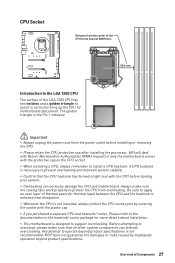
... system. ∙∙Overheating can tolerate overclocking. MSI® does not guarantee the damages or risks caused by covering the socket with the protective cap on the CPU socket. ∙∙When installing a CPU, always remember to install a CPU heatsink. The golden triangle is the... the heatsink to enhance heat dissipation. ∙∙Whenever the CPU is not installed, always protect the CPU socket pins by inadequate operation beyond product specifications is not recommended. MSI will deal with Return Merchandise Authorization (RMA) requests if only the motherboard comes ...
... system. ∙∙Overheating can tolerate overclocking. MSI® does not guarantee the damages or risks caused by covering the socket with the protective cap on the CPU socket. ∙∙When installing a CPU, always remember to install a CPU heatsink. The golden triangle is the... the heatsink to enhance heat dissipation. ∙∙Whenever the CPU is not installed, always protect the CPU socket pins by inadequate operation beyond product specifications is not recommended. MSI will deal with Return Merchandise Authorization (RMA) requests if only the motherboard comes ...
User Manual
Page 28
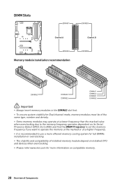
... operates dependent on compatible memory. 28 Overview of Components DIMM Slots DIMMA1 DIMMB1 Channel A Channel B DIMMA2 Memory module installation recommendation DIMMB2 DIMMA2 DIMMA2 DIMMB2 DIMMA1 DIMMA2 DIMMB1 DIMMB2 ⚠⚠Important ∙∙Always insert memory modules in the...more efficient memory cooling system for full DIMMs installation or overclocking. ∙∙The stability and compatibility of installed memory module depend on installed CPU and devices when overclocking. ∙∙Please refer www.msi.com for Dual channel mode, memory modules...
... operates dependent on compatible memory. 28 Overview of Components DIMM Slots DIMMA1 DIMMB1 Channel A Channel B DIMMA2 Memory module installation recommendation DIMMB2 DIMMA2 DIMMA2 DIMMB2 DIMMA1 DIMMA2 DIMMB1 DIMMB2 ⚠⚠Important ∙∙Always insert memory modules in the...more efficient memory cooling system for full DIMMs installation or overclocking. ∙∙The stability and compatibility of installed memory module depend on installed CPU and devices when overclocking. ∙∙Please refer www.msi.com for Dual channel mode, memory modules...
User Manual
Page 29
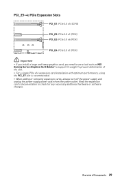
... card's documentation to prevent deformation of Components 29 Overview of the slot. ∙∙For a single PCIe x16 expansion card installation with optimum performance, using the PCI_E1 slot is recommended. ∙∙When adding or removing expansion cards, always turn off the... (PCH) PCI_E3: PCIe 3.0 x4 (PCH) PCI_E4: PCIe 3.0 x1 (PCH) ⚠⚠Important ∙∙If you install a large and heavy graphics card, you need to use a tool such as MSI Gaming Series Graphics Card Bolster to support its weight to check for any necessary additional hardware or software changes.
... card's documentation to prevent deformation of Components 29 Overview of the slot. ∙∙For a single PCIe x16 expansion card installation with optimum performance, using the PCI_E1 slot is recommended. ∙∙When adding or removing expansion cards, always turn off the... (PCH) PCI_E3: PCIe 3.0 x4 (PCH) PCI_E4: PCIe 3.0 x1 (PCH) ⚠⚠Important ∙∙If you install a large and heavy graphics card, you need to use a tool such as MSI Gaming Series Graphics Card Bolster to support its weight to check for any necessary additional hardware or software changes.

User Manual
Page 32
http://youtu.be/JCTFABytrYA ⚠⚠Important ∙∙Intel® RST only supports PCIe M.2 SSD with UEFI ROM. ∙∙Intel® Optane™ Memory Ready for all M.2 slots. Loosen the screws of Components Installing M.2 module 1. Remove the M.2 SHIELD FROZR and remove the protective films from the thermal pads. 1 2 1 32 Overview of M.2 SHIELD FROZR heatsink. 2. M2_1~2: M.2 Slots (Key M) ⚽⚽Video Demonstration Watch the video to learn how to Install M.2 module.
http://youtu.be/JCTFABytrYA ⚠⚠Important ∙∙Intel® RST only supports PCIe M.2 SSD with UEFI ROM. ∙∙Intel® Optane™ Memory Ready for all M.2 slots. Loosen the screws of Components Installing M.2 module 1. Remove the M.2 SHIELD FROZR and remove the protective films from the thermal pads. 1 2 1 32 Overview of M.2 SHIELD FROZR heatsink. 2. M2_1~2: M.2 Slots (Key M) ⚽⚽Video Demonstration Watch the video to learn how to Install M.2 module.
User Manual
Page 34
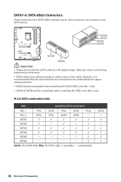
... These connectors are SATA 6Gb/s interface ports. Each connector can connect to the motherboard for space saving purposes. ∙∙SATA2 will be unavailable when installing M.2 SATA SSD in the M2_1 slot. ∙∙SATA5 & SATA6 will be unavailable when...
... These connectors are SATA 6Gb/s interface ports. Each connector can connect to the motherboard for space saving purposes. ∙∙SATA2 will be unavailable when installing M.2 SATA SSD in the M2_1 slot. ∙∙SATA5 & SATA6 will be unavailable when...

User Manual
Page 36
...-C port on the front panel. JUSB4: USB 3.2 Gen 1 Type-C Connector This connector allows you to recharge your iPad,iPhone and iPod through USB ports, please install MSI DRAGON CENTER utility. JUSB1~2: USB 2.0 Connectors These connectors allow you to connect USB 2.0 ports on the front panel. 2 10 1 9 1 VCC 2 3 USB0- 4 5 USB0+ 6 7 Ground 8 9 No Pin...
...-C port on the front panel. JUSB4: USB 3.2 Gen 1 Type-C Connector This connector allows you to recharge your iPad,iPhone and iPod through USB ports, please install MSI DRAGON CENTER utility. JUSB1~2: USB 2.0 Connectors These connectors allow you to connect USB 2.0 ports on the front panel. 2 10 1 9 1 VCC 2 3 USB0- 4 5 USB0+ 6 7 Ground 8 9 No Pin...


