User Manual
Page 1
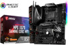
... diagrams about how to watch it with the web browser on your computer. Preparing Tools and Components AMD® AM4 CPU CPU Fan DDR4 Memory Power Supply Unit Chassis Graphics Card Thermal Paste SATA Hard Disk Drive SATA DVD Drive Phillips Screwdriver A Package of the installations also provide video demonstrations. Please link.... Some of Screws Quick Start 1 You may have even link to the URL by scanning the QR code. Quick Start Thank you for purchasing the MSI® MPG X570 GAMING EDGE WIFI motherboard.
... diagrams about how to watch it with the web browser on your computer. Preparing Tools and Components AMD® AM4 CPU CPU Fan DDR4 Memory Power Supply Unit Chassis Graphics Card Thermal Paste SATA Hard Disk Drive SATA DVD Drive Phillips Screwdriver A Package of the installations also provide video demonstrations. Please link.... Some of Screws Quick Start 1 You may have even link to the URL by scanning the QR code. Quick Start Thank you for purchasing the MSI® MPG X570 GAMING EDGE WIFI motherboard.

User Manual
Page 2
... to user guide. ƒ The motherboard has been dropped and damaged. ƒ The motherboard has obvious sign of static electricity by the edges to avoid touching sensitive components. y Do not boot the computer before handling the motherboard. y If you can not step on the motherboard ... outlet provides the same voltage as injury to the electrical outlet. y Always turn off the power supply and unplug the power cord from the power outlet before connecting the PSU to the user. y Place the power cord such a way that all components are securely connected. y All cautions and warnings on...
... to user guide. ƒ The motherboard has been dropped and damaged. ƒ The motherboard has obvious sign of static electricity by the edges to avoid touching sensitive components. y Do not boot the computer before handling the motherboard. y If you can not step on the motherboard ... outlet provides the same voltage as injury to the electrical outlet. y Always turn off the power supply and unplug the power cord from the power outlet before connecting the PSU to the user. y Place the power cord such a way that all components are securely connected. y All cautions and warnings on...

User Manual
Page 30
...;, ***: for any necessary additional hardware or software changes. y When adding or removing expansion cards, always turn off the power supply and unplug the power supply power cable from the power outlet. PCI_E1~5: PCIe Expansion Slots Slots 3rd Gen AMD Ryzen™ 2nd Gen AMD Ryzen™ Ryzen™ with Radeon...x1 PCIe 3.0 x1 PCIe 3.0 x1 Important y If you install a large and heavy graphics card, you need to use a tool such as MSI Gaming Series Graphics Card Bolster to support its weight to check for Ryzen™ with Radeon™ Vega Graphics and 2nd Gen AMD Ryzen™ ...
...;, ***: for any necessary additional hardware or software changes. y When adding or removing expansion cards, always turn off the power supply and unplug the power supply power cable from the power outlet. PCI_E1~5: PCIe Expansion Slots Slots 3rd Gen AMD Ryzen™ 2nd Gen AMD Ryzen™ Ryzen™ with Radeon...x1 PCIe 3.0 x1 PCIe 3.0 x1 Important y If you install a large and heavy graphics card, you need to use a tool such as MSI Gaming Series Graphics Card Bolster to support its weight to check for Ryzen™ with Radeon™ Vega Graphics and 2nd Gen AMD Ryzen™ ...

User Manual
Page 34
... These connectors allow you to connect an ATX power supply. 1 2 3 4 1 2 1 2 3 12 24 4 5 6 ATX_PWR1 7 8 1 13 9 10 11 12 8 4 Ground Ground Ground Ground 5 CPU_PWR1 1 5 +12V 6 +12V 7 +12V 8 +12V 4 2 Ground Ground 3 CPU_PWR2 1 3 4 +12V +12V +3.3V 13 +3.3V 14 ... +12V 22 +12V 23 +3.3V 24 +3.3V -12V Ground PS-ON# Ground Ground Ground Res +5V +5V +5V Ground Important Make sure that all the power cables are securely connected to a proper ATX power supply to ensure stable operation of the motherboard. 34 Overview of Components
... These connectors allow you to connect an ATX power supply. 1 2 3 4 1 2 1 2 3 12 24 4 5 6 ATX_PWR1 7 8 1 13 9 10 11 12 8 4 Ground Ground Ground Ground 5 CPU_PWR1 1 5 +12V 6 +12V 7 +12V 8 +12V 4 2 Ground Ground 3 CPU_PWR2 1 3 4 +12V +12V +3.3V 13 +3.3V 14 ... +12V 22 +12V 23 +3.3V 24 +3.3V -12V Ground PS-ON# Ground Ground Ground Res +5V +5V +5V Ground Important Make sure that all the power cables are securely connected to a proper ATX power supply to ensure stable operation of the motherboard. 34 Overview of Components

User Manual
Page 40
y Please use MSI's software to 2 meters continuous 5050 RGB LED strips (12V/G/R/B) with the maximum power rating of Components y Always turn off the power supply and unplug the power cord from the power outlet before installing or removing the RGB LED strip. JRGB1~2: RGB LED connectors The JRGB connectors allow you to connect the 5050 RGB LED...
y Please use MSI's software to 2 meters continuous 5050 RGB LED strips (12V/G/R/B) with the maximum power rating of Components y Always turn off the power supply and unplug the power cord from the power outlet before installing or removing the RGB LED strip. JRGB1~2: RGB LED connectors The JRGB connectors allow you to connect the 5050 RGB LED...
User Manual
Page 41
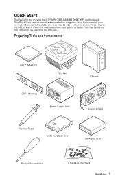
...up to 200 LEDs. Overview of 3A (5V). In the case of LED strips. y Always turn off the power supply and unplug the power cord from the power outlet before installing or removing the RGB LED strip. JRAINBOW1~2: Addressable RGB LED connectors The JRAINBOW connectors allow you ...to control the extended LED strip. y Please use MSI's software to connect the WS2812B Individually Addressable RGB LED strips 5V. 1 1 +...
...up to 200 LEDs. Overview of 3A (5V). In the case of LED strips. y Always turn off the power supply and unplug the power cord from the power outlet before installing or removing the RGB LED strip. JRAINBOW1~2: Addressable RGB LED connectors The JRAINBOW connectors allow you ...to control the extended LED strip. y Please use MSI's software to connect the WS2812B Individually Addressable RGB LED strips 5V. 1 1 +...
User Manual
Page 45
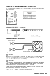
Plug the USB flash drive that matches your motherboard model from MSI® website and rename the BIOS file to the root of USB flash drive. Connect power supply to flash BIOS, and the LED near the Button starts flashing. 4. Important Only the FAT32 format USB flash drive supports...1. Press the Flash BIOS Button to CPU_PWR1 and ATX_PWR1. (No other components are necessary but power supply.) 2. Updating BIOS with Flash BIOS Button Before updating: Please download the latest BIOS file that contains the MSI.ROM file into the Flash BIOS Port on rear I/O panel. 3. BIOS Setup 45 After...
Plug the USB flash drive that matches your motherboard model from MSI® website and rename the BIOS file to the root of USB flash drive. Connect power supply to flash BIOS, and the LED near the Button starts flashing. 4. Important Only the FAT32 format USB flash drive supports...1. Press the Flash BIOS Button to CPU_PWR1 and ATX_PWR1. (No other components are necessary but power supply.) 2. Updating BIOS with Flash BIOS Button Before updating: Please download the latest BIOS file that contains the MSI.ROM file into the Flash BIOS Port on rear I/O panel. 3. BIOS Setup 45 After...
User Manual
Page 60
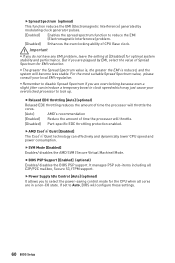
...Disabled] for EMI reduction. fAMD Cool'n'Quiet [Enabled] The Cool'n'Quiet technology can introduce a temporary boost in a non-CO state. fPower Supply Idle Control [Auto] (optional) It allows you are in clock speed which may just cause your local EMI regulation. It manages PSP ...sub-items including all cores are overclocking because even a slight jitter can effectively and dynamically lower CPU speed and power consumption. fRelaxed EDC throttling [Auto] (optional) Relaxed EDC throttling reduces the amount of time the processor will throttle. [Disabled] Part...
...Disabled] for EMI reduction. fAMD Cool'n'Quiet [Enabled] The Cool'n'Quiet technology can introduce a temporary boost in a non-CO state. fPower Supply Idle Control [Auto] (optional) It allows you are in clock speed which may just cause your local EMI regulation. It manages PSP ...sub-items including all cores are overclocking because even a slight jitter can effectively and dynamically lower CPU speed and power consumption. fRelaxed EDC throttling [Auto] (optional) Relaxed EDC throttling reduces the amount of time the processor will throttle. [Disabled] Part...
User Manual
Page 73
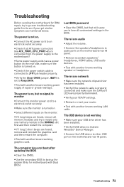
... all memory modules and try to go over troubleshooting guide first to the motherboard? y If 3 long beeps are properly illuminated. y Some power supply units have a power button on . y Connect the speakers/headphones to an electrical outlet securely. The USB device is on the motherboard rear IO panel. y Check... to bootup the system (Only for RMA repair, try to Keep DATA. The power is properly connected and make sure the button is turned on . y If 1 long 2 short beeps are connected from the power supply to see if your router. y Verify if the network cable is not on ...
... all memory modules and try to go over troubleshooting guide first to the motherboard? y If 3 long beeps are properly illuminated. y Some power supply units have a power button on . y Connect the speakers/headphones to an electrical outlet securely. The USB device is on the motherboard rear IO panel. y Check... to bootup the system (Only for RMA repair, try to Keep DATA. The power is properly connected and make sure the button is turned on . y If 1 long 2 short beeps are connected from the power supply to see if your router. y Verify if the network cable is not on ...


