User Manual
Page 1
.... Preparing Tools and Components AMD® AM4 CPU CPU Fan DDR4 Memory Power Supply Unit Chassis Graphics Card Thermal Paste SATA Hard Disk Drive SATA DVD Drive Phillips Screwdriver A Package of the installations also provide video demonstrations. Quick Start Thank you for purchasing the MSI® MPG X570 GAMING EDGE WIFI motherboard. Please link to the URL to the...
.... Preparing Tools and Components AMD® AM4 CPU CPU Fan DDR4 Memory Power Supply Unit Chassis Graphics Card Thermal Paste SATA Hard Disk Drive SATA DVD Drive Phillips Screwdriver A Package of the installations also provide video demonstrations. Quick Start Thank you for purchasing the MSI® MPG X570 GAMING EDGE WIFI motherboard. Please link to the URL to the...
User Manual
Page 13
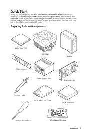
...Card 10 Connecting Peripheral Devices 11 Power On...12 Specifications...15 Package contents 20 Block Diagram ...21 Rear I/O Panel ...22 LAN Port LED Status Table 22 Audio Ports Configuration 22 Realtek Audio Console 23 Overview of Components 26 CPU Socket ...28 DIMM Slots...29 ...PCI_E1~5: PCIe Expansion Slots 30 M2_1~2: M.2 Slots (Key M 31 SATA1~6: SATA 6Gb/s Connectors 33 JFP1, JFP2: Front Panel Connectors 33 CPU_PWR1~2, ATX_PWR1: Power Connectors 34 CPU_FAN1, PUMP_FAN1, SYS_FAN1~4: Fan Connectors...
...Card 10 Connecting Peripheral Devices 11 Power On...12 Specifications...15 Package contents 20 Block Diagram ...21 Rear I/O Panel ...22 LAN Port LED Status Table 22 Audio Ports Configuration 22 Realtek Audio Console 23 Overview of Components 26 CPU Socket ...28 DIMM Slots...29 ...PCI_E1~5: PCIe Expansion Slots 30 M2_1~2: M.2 Slots (Key M 31 SATA1~6: SATA 6Gb/s Connectors 33 JFP1, JFP2: Front Panel Connectors 33 CPU_PWR1~2, ATX_PWR1: Power Connectors 34 CPU_FAN1, PUMP_FAN1, SYS_FAN1~4: Fan Connectors...
User Manual
Page 17
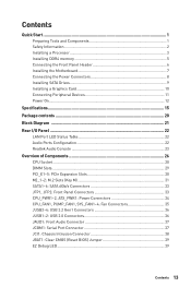
Continued from previous page y AMD® X570 Chipset ƒ 2x USB 3.2 Gen 2 (SuperSpeed USB 10Gbps) Type-A ports on the back panel ƒ 4x USB 3.2 Gen 1 (SuperSpeed USB) ports through the internal USB 3.2 ... y 1x 8-pin ATX 12V power connector y 1x 4-pin ATX 12V power connector y 6x SATA 6Gb/s connectors y 2x USB 2.0 connectors (supports additional 4 USB 2.0 ports) y 2x USB 3.2 Gen1 connectors (supports additional 4 USB 3.2 Gen1 ports) y 1x 4-pin CPU fan connector y 1x 4-pin water-pump connector y 4x 4-pin system fan connectors y 1x Front panel audio connector y 2x...
Continued from previous page y AMD® X570 Chipset ƒ 2x USB 3.2 Gen 2 (SuperSpeed USB 10Gbps) Type-A ports on the back panel ƒ 4x USB 3.2 Gen 1 (SuperSpeed USB) ports through the internal USB 3.2 ... y 1x 8-pin ATX 12V power connector y 1x 4-pin ATX 12V power connector y 6x SATA 6Gb/s connectors y 2x USB 2.0 connectors (supports additional 4 USB 2.0 ports) y 2x USB 3.2 Gen1 connectors (supports additional 4 USB 3.2 Gen1 ports) y 1x 4-pin CPU fan connector y 1x 4-pin water-pump connector y 4x 4-pin system fan connectors y 1x Front panel audio connector y 2x...
User Manual
Page 27
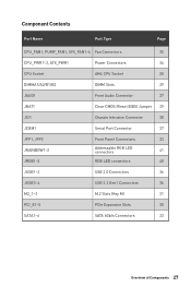
Component Contents Port Name Port Type Page CPU_FAN1, PUMP_FAN1, SYS_FAN1~4 Fan Connectors 35 CPU_PWR1~2, ATX_PWR1 Power Connectors 34 CPU Socket AM4 CPU Socket 28 DIMMA1/A2/B1/B2 DIMM Slots 29 JAUD1 Front Audio Connector 37 JBAT1 Clear CMOS (Reset BIOS) Jumper 39 JCI1 Chassis Intrusion Connector ...
Component Contents Port Name Port Type Page CPU_FAN1, PUMP_FAN1, SYS_FAN1~4 Fan Connectors 35 CPU_PWR1~2, ATX_PWR1 Power Connectors 34 CPU Socket AM4 CPU Socket 28 DIMMA1/A2/B1/B2 DIMM Slots 29 JAUD1 Front Audio Connector 37 JBAT1 Clear CMOS (Reset BIOS) Jumper 39 JCI1 Chassis Intrusion Connector ...
User Manual
Page 28
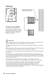
...BIOS to default values, due to protect the CPU from overheating. CPU Socket Distance from the center of the CPU to the nearest DIMM slot. 52.5 mm Introduction to the AM4 CPU The surface of Components y Always unplug the power cord from the power outlet before booting your system. y If you...thermal paste (or thermal tape) between the CPU and the heatsink to operate beyond product specifications. 28 Overview of the AM4 CPU has a yellow triangle to the documentation in correctly lining up the CPU for more details about installation. MSI® does not guarantee the damages or risks...
...BIOS to default values, due to protect the CPU from overheating. CPU Socket Distance from the center of the CPU to the nearest DIMM slot. 52.5 mm Introduction to the AM4 CPU The surface of Components y Always unplug the power cord from the power outlet before booting your system. y If you...thermal paste (or thermal tape) between the CPU and the heatsink to operate beyond product specifications. 28 Overview of the AM4 CPU has a yellow triangle to the documentation in correctly lining up the CPU for more details about installation. MSI® does not guarantee the damages or risks...

User Manual
Page 30
PCIe bandwidth table Slot Single 2-Way PCI_E1 (CPU) @4.0 x16* or @3.0 x16** or @3.0 x8*** @4.0 x16* or @3.0 x16** or @3.0 x8*** PCI_E2 (PCH) 3.0 x1 ― ...of Components y When adding or removing expansion cards, always turn off the power supply and unplug the power supply power cable from the power outlet. PCI_E1~5: PCIe Expansion Slots Slots 3rd Gen AMD Ryzen™ ...Important y If you install a large and heavy graphics card, you need to use a tool such as MSI Gaming Series Graphics Card Bolster to support its weight to check for Ryzen™ with Radeon™ Vega Graphics...
PCIe bandwidth table Slot Single 2-Way PCI_E1 (CPU) @4.0 x16* or @3.0 x16** or @3.0 x8*** @4.0 x16* or @3.0 x16** or @3.0 x8*** PCI_E2 (PCH) 3.0 x1 ― ...of Components y When adding or removing expansion cards, always turn off the power supply and unplug the power supply power cable from the power outlet. PCI_E1~5: PCIe Expansion Slots Slots 3rd Gen AMD Ryzen™ ...Important y If you install a large and heavy graphics card, you need to use a tool such as MSI Gaming Series Graphics Card Bolster to support its weight to check for Ryzen™ with Radeon™ Vega Graphics...
User Manual
Page 39
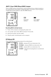
...cap from a battery located on the computer. CPU - Overview of the motherboard. Keep Data (default) Clear CMOS/ Reset BIOS Resetting BIOS to save system configuration data. Power off the computer and unplug the power cord 2. indicates GPU is external powered from JBAT1. 4. JBAT1: Clear CMOS (...Reset BIOS) Jumper There is CMOS memory onboard that is not detected or fail. indicates CPU is not detected or fail.
...cap from a battery located on the computer. CPU - Overview of the motherboard. Keep Data (default) Clear CMOS/ Reset BIOS Resetting BIOS to save system configuration data. Power off the computer and unplug the power cord 2. indicates GPU is external powered from JBAT1. 4. JBAT1: Clear CMOS (...Reset BIOS) Jumper There is CMOS memory onboard that is not detected or fail. indicates CPU is not detected or fail.
User Manual
Page 49
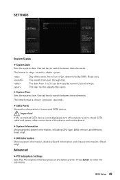
... of the week, from Jan. through Dec. f System Time Sets the system time. f System Information Shows detailed system information, including CPU type, BIOS version, and Memory (read only). BIOS Setup 49 SETTINGS System Status f System Date Sets the system date. Use tab ...and chassis Information. (Read only). Important If the connected SATA device is not displayed, turn off computer and re-check SATA cable and power cable connections of connected SATA device. Press Enter to switch between date elements. The month from Sun to switch between time elements. The...
... of the week, from Jan. through Dec. f System Time Sets the system time. f System Information Shows detailed system information, including CPU type, BIOS version, and Memory (read only). BIOS Setup 49 SETTINGS System Status f System Date Sets the system date. Use tab ...and chassis Information. (Read only). Important If the connected SATA device is not displayed, turn off computer and re-check SATA cable and power cable connections of connected SATA device. Press Enter to switch between date elements. The month from Sun to switch between time elements. The...
User Manual
Page 50
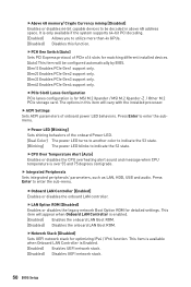
... vary with the installed processor. f ACPI Settings Sets ACPI parameters of the onboard Power LED. [Dual Color] The power LED turns to another color to indicate the S3 state. [Blinking] The power LED blinks to indicate the S3 state. fPCIe SlotX Lanes Configuration PCIe lanes confi... Switch [Auto] Sets PCI Express protocol of PCIe x16 slots for MSI M.2 Xpander / MSI M.2 Xpander-Z / Other M.2 PCIe storage card. fCPU Over Temperature Alert [Auto] Enables or disables the CPU overheating alert sound and message when CPU temperature is over 55 and 75 degrees centigrade. Press Enter to enter...
... vary with the installed processor. f ACPI Settings Sets ACPI parameters of the onboard Power LED. [Dual Color] The power LED turns to another color to indicate the S3 state. [Blinking] The power LED blinks to indicate the S3 state. fPCIe SlotX Lanes Configuration PCIe lanes confi... Switch [Auto] Sets PCI Express protocol of PCIe x16 slots for MSI M.2 Xpander / MSI M.2 Xpander-Z / Other M.2 PCIe storage card. fCPU Over Temperature Alert [Auto] Enables or disables the CPU overheating alert sound and message when CPU temperature is over 55 and 75 degrees centigrade. Press Enter to enter...
User Manual
Page 57
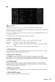
y Overclocking is only recommended for advanced users. Note: We use GAME BOOST function for OC expert to configure in OC menu will be changed if the processor supports this function. f CPU Ratio [Auto] Sets the CPU ratio that is not guaranteed. f A-XMP [Disabled] Please enable A-XMP or select a profile...] Enables or disables to use * as the symbol for overclocking the memory. BIOS Setup 57 This item can set the parameters about CPU power/ current. If it could void your warranty or severely damage your PC manually is not guaranteed, and if done improperly, it occurs,...
y Overclocking is only recommended for advanced users. Note: We use GAME BOOST function for OC expert to configure in OC menu will be changed if the processor supports this function. f CPU Ratio [Auto] Sets the CPU ratio that is not guaranteed. f A-XMP [Disabled] Please enable A-XMP or select a profile...] Enables or disables to use * as the symbol for overclocking the memory. BIOS Setup 57 This item can set the parameters about CPU power/ current. If it could void your warranty or severely damage your PC manually is not guaranteed, and if done improperly, it occurs,...
User Manual
Page 58
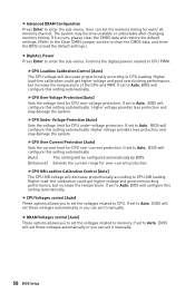
... voltages related to Auto, BIOS will configure this setting automatically. f Advanced DRAM Configuration Press Enter to CPU PWM. Controls the digital powers related to enter the sub-menu. fCPU Over Voltage Protection [Auto] Sets the voltage limit for each/ all memory channel.... could get higher voltage and good overclocking performance, but increase the temperature. fCPU Under Voltage Protection [Auto] Sets the voltage limit for CPU over -current protection. The system may become unstable or unbootable after changing memory timing. If it manually. If set to set it ...
... voltages related to Auto, BIOS will configure this setting automatically. f Advanced DRAM Configuration Press Enter to CPU PWM. Controls the digital powers related to enter the sub-menu. fCPU Over Voltage Protection [Auto] Sets the voltage limit for each/ all memory channel.... could get higher voltage and good overclocking performance, but increase the temperature. fCPU Under Voltage Protection [Auto] Sets the voltage limit for CPU over -current protection. The system may become unstable or unbootable after changing memory timing. If it manually. If set to set it ...
User Manual
Page 59
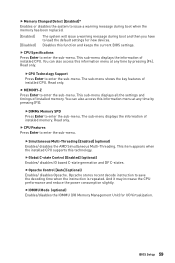
...information menu at any time by pressing [F4]. This item appears when the installed CPU supports this function and keeps the current BIOS settings. And it may increase the CPU performance and reduce the power consumption slightly. f MEMORY-Z Press Enter to enter the sub-menu. BIOS Setup... 59 This sub-menu displays the information of installed CPU. You can also access this information menu at any ...
...information menu at any time by pressing [F4]. This item appears when the installed CPU supports this function and keeps the current BIOS settings. And it may increase the CPU performance and reduce the power consumption slightly. f MEMORY-Z Press Enter to enter the sub-menu. BIOS Setup... 59 This sub-menu displays the information of installed CPU. You can also access this information menu at any ...
User Manual
Page 60
...] Part-specific EDC throttling protection enabled. For the most suitable Spread Spectrum value, please consult your overclocked processor to select the power-saving control mode for optimal system stability and performance. y Remember to disable Spread Spectrum if you to lock up. fAMD Cool... state. It manages PSP sub-items including all cores are overclocking because even a slight jitter can effectively and dynamically lower CPU speed and power consumption. fPower Supply Idle Control [Auto] (optional) It allows you are in clock speed which may just cause your local...
...] Part-specific EDC throttling protection enabled. For the most suitable Spread Spectrum value, please consult your overclocked processor to select the power-saving control mode for optimal system stability and performance. y Remember to disable Spread Spectrum if you to lock up. fAMD Cool... state. It manages PSP sub-items including all cores are overclocking because even a slight jitter can effectively and dynamically lower CPU speed and power consumption. fPower Supply Idle Control [Auto] (optional) It allows you are in clock speed which may just cause your local...


