User Manual
Page 1
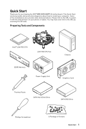
... you for purchasing the MSI® MEG Z690 UNIFY-X motherboard. Preparing Tools and Components Intel® LGA1700 CPU LGA1700 CPU Fan DDR5 Memory Power Supply Unit Chassis Graphics Card Thermal Paste SATA Hard Disk Drive SATA DVD Drive Phillips Screwdriver A Package of the installations also provide video demonstrations. Some of Screws Quick Start 1 This Quick Start section provides demonstration diagrams about how to install your phone or tablet. You may have even link to watch it with...
... you for purchasing the MSI® MEG Z690 UNIFY-X motherboard. Preparing Tools and Components Intel® LGA1700 CPU LGA1700 CPU Fan DDR5 Memory Power Supply Unit Chassis Graphics Card Thermal Paste SATA Hard Disk Drive SATA DVD Drive Phillips Screwdriver A Package of the installations also provide video demonstrations. Some of Screws Quick Start 1 This Quick Start section provides demonstration diagrams about how to install your phone or tablet. You may have even link to watch it with...

User Manual
Page 13
... a Processor 4 Installing DDR5 memory 5 Connecting the Front Panel Header 6 Installing the Motherboard 7 Connecting the Power Connectors 8 Installing SATA Drives 9 Installing a Graphics Card 10 Connecting Peripheral Devices 11 Power On...12 Specifications...15 Package contents 22 Block Diagram ...23 Rear I/O Panel...24 LAN Port LED Status Table 24 Audio Ports Configuration 24 Realtek Audio Console 25 Installing Antennas 27 Overview of Components 28 CPU Socket...30 DIMM Slots...31 PCI_E1~3: PCIe Expansion Slots 32 JFP1, JFP2: Front Panel Connectors 33 M2_1~5: M.2 Slots (Key...
... a Processor 4 Installing DDR5 memory 5 Connecting the Front Panel Header 6 Installing the Motherboard 7 Connecting the Power Connectors 8 Installing SATA Drives 9 Installing a Graphics Card 10 Connecting Peripheral Devices 11 Power On...12 Specifications...15 Package contents 22 Block Diagram ...23 Rear I/O Panel...24 LAN Port LED Status Table 24 Audio Ports Configuration 24 Realtek Audio Console 25 Installing Antennas 27 Overview of Components 28 CPU Socket...30 DIMM Slots...31 PCI_E1~3: PCIe Expansion Slots 32 JFP1, JFP2: Front Panel Connectors 33 M2_1~5: M.2 Slots (Key...

User Manual
Page 14
... Multi-BIOS Switch 52 JRGB1: RGB LED connector 53 JRAINBOW1~2: Addressable RGB LED connectors 54 JCORSAIR1: CORSAIR Connector 55 Onboard LEDs...56 EZ Debug LED...56 Debug Code LED...56 Hexadecimal Character Table 56 Boot Phases...56 Debug Code LED Table 57 ACPI States Codes 61 CPU Temperature 61 Installing OS, Drivers & MSI Center 62 Installing Windows® 10 62 Installing Drivers 62 MSI Center...62 UEFI BIOS...63 BIOS Setup...64 Entering BIOS Setup 64 BIOS User Guide...64 Resetting BIOS...65 Updating BIOS...65 RAID Configuration 67 Intel® Optane™ Memory Configuration...
... Multi-BIOS Switch 52 JRGB1: RGB LED connector 53 JRAINBOW1~2: Addressable RGB LED connectors 54 JCORSAIR1: CORSAIR Connector 55 Onboard LEDs...56 EZ Debug LED...56 Debug Code LED...56 Hexadecimal Character Table 56 Boot Phases...56 Debug Code LED Table 57 ACPI States Codes 61 CPU Temperature 61 Installing OS, Drivers & MSI Center 62 Installing Windows® 10 62 Installing Drivers 62 MSI Center...62 UEFI BIOS...63 BIOS Setup...64 Entering BIOS Setup 64 BIOS User Guide...64 Resetting BIOS...65 Updating BIOS...65 RAID Configuration 67 Intel® Optane™ Memory Configuration...

User Manual
Page 15
... memory slots, support up to 5600+ MHz ∙∙Supports Intel® XMP 3.0 OC ∙∙Supports Dual Controller Dual-Channel mode ∙∙Supports non-ECC, un-buffered memory *Please refer to www.msi.com for more information on compatible memory ∙∙Intel® Z690 Chipset ▪▪2x USB 3.2 Gen2x2 20Gbps ports ( 1 Type-C port on the back panel, 1 Type-C internal connector) ▪▪3x USB 3.2 Gen2 10Gbps Type-A ports on the back panel ▪▪2x USB 2.0 Type-A port...
... memory slots, support up to 5600+ MHz ∙∙Supports Intel® XMP 3.0 OC ∙∙Supports Dual Controller Dual-Channel mode ∙∙Supports non-ECC, un-buffered memory *Please refer to www.msi.com for more information on compatible memory ∙∙Intel® Z690 Chipset ▪▪2x USB 3.2 Gen2x2 20Gbps ports ( 1 Type-C port on the back panel, 1 Type-C internal connector) ▪▪3x USB 3.2 Gen2 10Gbps Type-A ports on the back panel ▪▪2x USB 2.0 Type-A port...

User Manual
Page 16
...-GPU Storage RAID Audio LAN 16 Specifications Continued from previous page ∙∙Supports NVIDIA® SLI Technology ∙∙Supports AMD® CrossFire™ Technology ∙∙6x SATA 6Gb/s ports ▪▪SATA5~8 (From Z690 Chipset) ▪▪SATAA~B1 (From ASMedia ASM1061) ∙∙5x M.2 slots (Key M) ▪▪M2_1 slot (From CPU) ▫▫Supports PCIe 4.0 x4 ▫▫Supports 2260/ 2280 storage devices ▪▪M2_2 slot (From Z690 Chipset) ▫▫Supports PCIe...
...-GPU Storage RAID Audio LAN 16 Specifications Continued from previous page ∙∙Supports NVIDIA® SLI Technology ∙∙Supports AMD® CrossFire™ Technology ∙∙6x SATA 6Gb/s ports ▪▪SATA5~8 (From Z690 Chipset) ▪▪SATAA~B1 (From ASMedia ASM1061) ∙∙5x M.2 slots (Key M) ▪▪M2_1 slot (From CPU) ▫▫Supports PCIe 4.0 x4 ▫▫Supports 2260/ 2280 storage devices ▪▪M2_2 slot (From Z690 Chipset) ▫▫Supports PCIe...

User Manual
Page 18
... Low temperature booting jumpers ∙∙1x Safe boot jumper ∙∙1x OC Retry jumper ∙∙1x 2-Digit Debug Code LED ∙∙4x EZ Debug LED ∙∙1x 4-pin RGB LED connector ∙∙2x 3-pin RAINBOW LED connectors ∙∙1x 3-pin JCORSAIR LED connector ∙∙1x Clear CMOS button ∙∙1x Flash BIOS button ∙∙1x PS/2 port ∙∙2x USB 2.0 Type-A ports ∙∙2x 2.5Gbps LAN (RJ45) ports ∙...
... Low temperature booting jumpers ∙∙1x Safe boot jumper ∙∙1x OC Retry jumper ∙∙1x 2-Digit Debug Code LED ∙∙4x EZ Debug LED ∙∙1x 4-pin RGB LED connector ∙∙2x 3-pin RAINBOW LED connectors ∙∙1x 3-pin JCORSAIR LED connector ∙∙1x Clear CMOS button ∙∙1x Flash BIOS button ∙∙1x PS/2 port ∙∙2x USB 2.0 Type-A ports ∙∙2x 2.5Gbps LAN (RJ45) ports ∙...

User Manual
Page 29
... Port Type Multi-BIOS Switch Fan Connectors Power Connectors LGA1700 CPU Socket Memory slots Front Audio Connector Clear CMOS (Reset BIOS) Jumper Chassis Intrusion Connector CORSAIR Connector Tuning Controller connector Front Panel Connectors Low Temperature Booting Jumper Safe Boot Jumper OC Retry Button Connector Addressable RGB LED connectors RGB LED connector Slow Mode Booting Jumper Thunderbolt Add-on Card Connector TPM Module Connector USB 2.0 Connectors USB 3.2 Gen 1 Connectors USB 3.2 Gen 2x2 Type-C Connector M.2 Slots (Key M) PCIe Expansion Slots Power Button, Reset Button SATA...
... Port Type Multi-BIOS Switch Fan Connectors Power Connectors LGA1700 CPU Socket Memory slots Front Audio Connector Clear CMOS (Reset BIOS) Jumper Chassis Intrusion Connector CORSAIR Connector Tuning Controller connector Front Panel Connectors Low Temperature Booting Jumper Safe Boot Jumper OC Retry Button Connector Addressable RGB LED connectors RGB LED connector Slow Mode Booting Jumper Thunderbolt Add-on Card Connector TPM Module Connector USB 2.0 Connectors USB 3.2 Gen 1 Connectors USB 3.2 Gen 2x2 Type-C Connector M.2 Slots (Key M) PCIe Expansion Slots Power Button, Reset Button SATA...

User Manual
Page 30
... sure the cooling fans work properly to overclock, please make sure that the CPU heatsink has formed a tight seal with the CPU before installing or removing the CPU. ∙∙Please retain the CPU protective cap after installing the processor. A CPU heatsink is not recommended. Before attempting to protect the CPU from the power outlet before booting your system. ∙∙Overheating can tolerate overclocking. MSI® does not...
... sure the cooling fans work properly to overclock, please make sure that the CPU heatsink has formed a tight seal with the CPU before installing or removing the CPU. ∙∙Please retain the CPU protective cap after installing the processor. A CPU heatsink is not recommended. Before attempting to protect the CPU from the power outlet before booting your system. ∙∙Overheating can tolerate overclocking. MSI® does not...

User Manual
Page 32
... the power supply power cable from the power outlet. Installing SLI graphics cards For power supply recommendations for SLI configurations, Please refer to make sure you need to use a tool such as MSI Graphics Card Bolster to support its weight to check for any necessary additional hardware or software changes. Read the expansion card's documentation to prevent deformation of the slot. ∙∙For a single PCIe x16 expansion card installation with optimum performance, using the SLI Bridge Connector...
... the power supply power cable from the power outlet. Installing SLI graphics cards For power supply recommendations for SLI configurations, Please refer to make sure you need to use a tool such as MSI Graphics Card Bolster to support its weight to check for any necessary additional hardware or software changes. Read the expansion card's documentation to prevent deformation of the slot. ∙∙For a single PCIe x16 expansion card installation with optimum performance, using the SLI Bridge Connector...

User Manual
Page 33
... the power cord, power up the computer and install the drivers and software included in the SLI configuration menu, and then click Apply. JFP1, JFP2: Front Panel Connectors These connectors connect to the JFP1. 3 5 7 9 JFP1 2 1 + 10 9 Reserved HDD LED Reset Switch HDD LED + 2 HDD LED - 4 Reset Switch 6 Reset Switch 8 Reserved 10 Power LED + Power LED Power Switch Power Switch No Pin Overview of the graphics cards. 4. Right-click the Windows desktop and select NVIDIA Control Panel from the menu, click on the front panel. Connect all PCIe power connectors of...
... the power cord, power up the computer and install the drivers and software included in the SLI configuration menu, and then click Apply. JFP1, JFP2: Front Panel Connectors These connectors connect to the JFP1. 3 5 7 9 JFP1 2 1 + 10 9 Reserved HDD LED Reset Switch HDD LED + 2 HDD LED - 4 Reset Switch 6 Reset Switch 8 Reserved 10 Power LED + Power LED Power Switch Power Switch No Pin Overview of the graphics cards. 4. Right-click the Windows desktop and select NVIDIA Control Panel from the menu, click on the front panel. Connect all PCIe power connectors of...

User Manual
Page 43
... Debug Code LED Reset Clear CMOS 88 1 Tuning Controller JDASH1 Tuning Controller cable OC button- these buttons are used to the Debug Code LED table in Safe Boot mode. press and hold this manual for retrying OC settings until the system boot up successfully. ∙∙ Clear CMOS - Please follow the instructions below to decrease/ increase the CPU base clock/ CPU ratio. this button allows you to be overclocked. ∙∙ Reset - OC Retry Using Tuning Controller Power Tuning controller is used to...
... Debug Code LED Reset Clear CMOS 88 1 Tuning Controller JDASH1 Tuning Controller cable OC button- these buttons are used to the Debug Code LED table in Safe Boot mode. press and hold this manual for retrying OC settings until the system boot up successfully. ∙∙ Clear CMOS - Please follow the instructions below to decrease/ increase the CPU base clock/ CPU ratio. this button allows you to be overclocked. ∙∙ Reset - OC Retry Using Tuning Controller Power Tuning controller is used to...

User Manual
Page 52
Multi-BIOS LED (Red: BIOS B, White: BIOS A) BIOS B BIOS A (Default) ⚠⚠Important ∙∙Do not use the MSI Center or Flash BIOS Button to default values 1. Keep Data (default) Clear CMOS/ Reset BIOS Resetting BIOS to flash BIOS. Use a jumper cap to clear the CMOS memory. Plug the power cord and Power on the motherboard to BIOS section for details. 52 Overview of Components If you can also use the Multi-BIOS switch when system is booting up. ∙∙You can shift to the...
Multi-BIOS LED (Red: BIOS B, White: BIOS A) BIOS B BIOS A (Default) ⚠⚠Important ∙∙Do not use the MSI Center or Flash BIOS Button to default values 1. Keep Data (default) Clear CMOS/ Reset BIOS Resetting BIOS to flash BIOS. Use a jumper cap to clear the CMOS memory. Plug the power cord and Power on the motherboard to BIOS section for details. 52 Overview of Components If you can also use the Multi-BIOS switch when system is booting up. ∙∙You can shift to the...

User Manual
Page 58
... memory initialization error 55 Memory not installed 56 Invalid CPU type or Speed 57 CPU mismatch 58 CPU self test failed or possible CPU cache error 59 CPU micro-code is not found or micro-code update is failed 5A Internal CPU error 5B Reset PPI is not available 5C - 5F Reserved for future AMI error codes DXE Progress Codes 60 DXE Core is started 61 NVRAM initialization 62 Installation of the PCH Runtime Services 63 CPU...
... memory initialization error 55 Memory not installed 56 Invalid CPU type or Speed 57 CPU mismatch 58 CPU self test failed or possible CPU cache error 59 CPU micro-code is not found or micro-code update is failed 5A Internal CPU error 5B Reset PPI is not available 5C - 5F Reserved for future AMI error codes DXE Progress Codes 60 DXE Core is started 61 NVRAM initialization 62 Installation of the PCH Runtime Services 63 CPU...

User Manual
Page 59
... is started PCI Bus Hot Plug Controller Initialization PCI Bus Enumeration 32 PCI Bus Request Resources PCI Bus Assign Resources Console Output devices connect Console input devices connect Super IO Initialization USB initialization is started USB Reset USB Detect USB Enable Reserved for future AMI codes IDE initialization is started IDE Reset IDE Detect IDE Enable SCSI initialization is started SCSI Reset SCSI Detect SCSI Enable Setup Verifying Password Start of Setup Setup Input Wait Ready To Boot event Legacy Boot event Exit Boot Services event Runtime Set Virtual Address MAP Begin Onboard...
... is started PCI Bus Hot Plug Controller Initialization PCI Bus Enumeration 32 PCI Bus Request Resources PCI Bus Assign Resources Console Output devices connect Console input devices connect Super IO Initialization USB initialization is started USB Reset USB Detect USB Enable Reserved for future AMI codes IDE initialization is started IDE Reset IDE Detect IDE Enable SCSI initialization is started SCSI Reset SCSI Detect SCSI Enable Setup Verifying Password Start of Setup Setup Input Wait Ready To Boot event Legacy Boot event Exit Boot Services event Runtime Set Virtual Address MAP Begin Onboard...

User Manual
Page 60
... S3 Resume PPI not Found 60 Onboard LEDs B1 Runtime Set Virtual Address MAP End B2 Legacy Option ROM Initialization B3 System Reset B4 USB hot plug B5 PCI bus hot plug B6 Clean-up of NVRAM B7 Configuration Reset (reset of the Architectural Protocols are found D8 Invalid password D9 Error loading Boot Option (LoadImage returned error) DA Boot Option is failed (StartImage returned error) DB Flash update is failed DC Reset protocol is not available S3...
... S3 Resume PPI not Found 60 Onboard LEDs B1 Runtime Set Virtual Address MAP End B2 Legacy Option ROM Initialization B3 System Reset B4 USB hot plug B5 PCI bus hot plug B6 Clean-up of NVRAM B7 Configuration Reset (reset of the Architectural Protocols are found D8 Invalid password D9 Error loading Boot Option (LoadImage returned error) DA Boot Option is failed (StartImage returned error) DB Flash update is failed DC Reset protocol is not available S3...

User Manual
Page 62
... game settings and smoothly use content creation softwares. Installing OS, Drivers & MSI Center Please download and update the latest utilities and drivers at www.msi.com Installing Windows® 10 1. Insert the Windows® 10 installation disc/USB into your computer in the lower-right corner of the MSI USB Drive. 4. Press F11 key during the computer POST (Power-On Self Test) to control and synchronize LED light effects on PCs and other MSI products. Start up...
... game settings and smoothly use content creation softwares. Installing OS, Drivers & MSI Center Please download and update the latest utilities and drivers at www.msi.com Installing Windows® 10 1. Insert the Windows® 10 installation disc/USB into your computer in the lower-right corner of the MSI USB Drive. 4. Press F11 key during the computer POST (Power-On Self Test) to control and synchronize LED light effects on PCs and other MSI products. Start up...

User Manual
Page 65
... to reset BIOS: ∙∙Go to BIOS and press F6 to load optimized defaults. ∙∙Short the Clear CMOS jumper on the motherboard. ∙∙Press the Clear CMOS button on the rear I/O panel. ⚠⚠Important Be sure the computer is 100% completed, the system will reboot automatically. Select a BIOS file to enter BIOS. UEFI BIOS 65 Updating BIOS Updating BIOS with M-FLASH Before updating: Please download the latest BIOS file that contains the update file into the USB flash drive...
... to reset BIOS: ∙∙Go to BIOS and press F6 to load optimized defaults. ∙∙Short the Clear CMOS jumper on the motherboard. ∙∙Press the Clear CMOS button on the rear I/O panel. ⚠⚠Important Be sure the computer is 100% completed, the system will reboot automatically. Select a BIOS file to enter BIOS. UEFI BIOS 65 Updating BIOS Updating BIOS with M-FLASH Before updating: Please download the latest BIOS file that contains the update file into the USB flash drive...

User Manual
Page 66
... connection is set properly. ∙∙Please close all other application software before updating the BIOS. Plug the USB storage device that matches your motherboard model from the MSI® website. 2. After the flashing process is completed. 66 UEFI BIOS Connect the power supply to CPU_PWR1 and ATX_PWR1. (No need to update BIOS. 6. Please download the latest BIOS file that contains the MSI.ROM file into the Flash BIOS Port on Install button. 4. The system will automatically restart to install CPU and memory.) 4. The LED...
... connection is set properly. ∙∙Please close all other application software before updating the BIOS. Plug the USB storage device that matches your motherboard model from the MSI® website. 2. After the flashing process is completed. 66 UEFI BIOS Connect the power supply to CPU_PWR1 and ATX_PWR1. (No need to update BIOS. 6. Please download the latest BIOS file that contains the MSI.ROM file into the Flash BIOS Port on Install button. 4. The system will automatically restart to install CPU and memory.) 4. The LED...

User Manual
Page 69
...;∙Connect the USB device to other USB port on the monitor. ∙∙If 3 long beeps are heard, remove all ATX power connectors like ATX_PWR1, CPU_PWR1 are connected from the power supply to the motherboard? ∙∙Some power supply units have a power button on . ∙∙Check if the power switch cable is connected to see if your router. ∙∙Test with Dual BIOS) Troubleshooting 69 Troubleshooting Before sending the motherboard for motherboard with another known working power supply of...
...;∙Connect the USB device to other USB port on the monitor. ∙∙If 3 long beeps are heard, remove all ATX power connectors like ATX_PWR1, CPU_PWR1 are connected from the power supply to the motherboard? ∙∙Some power supply units have a power button on . ∙∙Check if the power switch cable is connected to see if your router. ∙∙Test with Dual BIOS) Troubleshooting 69 Troubleshooting Before sending the motherboard for motherboard with another known working power supply of...

User Manual
Page 73
... right to make changes to accuracy or completeness is a registered trademark of Micro-Star Int'l Co., Ltd. The MSI logo used is expressed or implied. Revision History Version 2.0, 2021/09, First release. MS-7D28 铅 汞 ...MSI website for further guidance. Alternatively, please try the following help resources for technical guide, BIOS updates, driver updates, and other marks and names mentioned may be obtained from the user guide, please contact your system and no solution can be trademarks of purchase or local distributor. Technical Support If a problem...
... right to make changes to accuracy or completeness is a registered trademark of Micro-Star Int'l Co., Ltd. The MSI logo used is expressed or implied. Revision History Version 2.0, 2021/09, First release. MS-7D28 铅 汞 ...MSI website for further guidance. Alternatively, please try the following help resources for technical guide, BIOS updates, driver updates, and other marks and names mentioned may be obtained from the user guide, please contact your system and no solution can be trademarks of purchase or local distributor. Technical Support If a problem...

