User Manual
Page 12
... Status Table 22 Audio Ports Configuration 22 Realtek Audio Console 23 Installing Antennas 25 Overview of Components 26 CPU Socket...28 DIMM Slots...29 PCI_E1~5: PCIe Expansion Slots 30 M2_1~3: M.2 Slots (Key M 32 SATA1~6: SATA 6Gb/s Connectors 34 JFP1, JFP2: Front Panel Connectors 35 CPU_PWR1~3, ATX_PWR1: Power Connectors 36 JBLK_U1: Base...
... Status Table 22 Audio Ports Configuration 22 Realtek Audio Console 23 Installing Antennas 25 Overview of Components 26 CPU Socket...28 DIMM Slots...29 PCI_E1~5: PCIe Expansion Slots 30 M2_1~3: M.2 Slots (Key M 32 SATA1~6: SATA 6Gb/s Connectors 34 JFP1, JFP2: Front Panel Connectors 35 CPU_PWR1~3, ATX_PWR1: Power Connectors 36 JBLK_U1: Base...
User Manual
Page 15
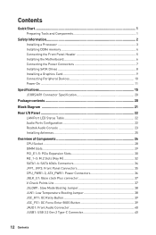
...; Technology ∙∙Supports 3-Way AMD® CrossFire™ Technology Intel® Z490 Chipset ∙∙6x SATA 6Gb/s ports* ∙∙3x M.2 slots (Key M) ▪▪M2_1 supports up to PCIe 3.0 x4 and SATA 6Gb/s, 2242/ 2260/ 2280/ 22110 storage devices* ▪▪... *** Before using the F SKU processors. Continued on compatible memory ∙∙3x PCIe 3.0 x16 slots (2 from CPU, 1 from PCH, support 16/0/4, 8/8/4) ∙∙2x PCIe x1 slots (from MSI website. Intel® Z490 Chipset ∙∙4x DDR4 memory slots, support up to 128GB* ∙∙...
...; Technology ∙∙Supports 3-Way AMD® CrossFire™ Technology Intel® Z490 Chipset ∙∙6x SATA 6Gb/s ports* ∙∙3x M.2 slots (Key M) ▪▪M2_1 supports up to PCIe 3.0 x4 and SATA 6Gb/s, 2242/ 2260/ 2280/ 22110 storage devices* ▪▪... *** Before using the F SKU processors. Continued on compatible memory ∙∙3x PCIe 3.0 x16 slots (2 from CPU, 1 from PCH, support 16/0/4, 8/8/4) ∙∙2x PCIe x1 slots (from MSI website. Intel® Z490 Chipset ∙∙4x DDR4 memory slots, support up to 128GB* ∙∙...
User Manual
Page 16
...8729;1x Optical S/PDIF OUT connector ∙∙5x OFC audio jacks Continued on next page 16 Specifications Continued from previous page Intel® Z490 Chipset RAID ∙∙Supports RAID 0, RAID1, RAID 5 and RAID 10 for SATA storage devices ∙∙Supports RAID 0, RAID 1 and RAID ...5 for M.2 PCIe storage devices LAN ∙∙1x Realtek® 8125B 2.5G LAN controller Intel® AX201 ∙∙MU-MIMO TX/RX, 2.4GHz/ 5GHz (160MHz...
...8729;1x Optical S/PDIF OUT connector ∙∙5x OFC audio jacks Continued on next page 16 Specifications Continued from previous page Intel® Z490 Chipset RAID ∙∙Supports RAID 0, RAID1, RAID 5 and RAID 10 for SATA storage devices ∙∙Supports RAID 0, RAID 1 and RAID ...5 for M.2 PCIe storage devices LAN ∙∙1x Realtek® 8125B 2.5G LAN controller Intel® AX201 ∙∙MU-MIMO TX/RX, 2.4GHz/ 5GHz (160MHz...
User Manual
Page 21
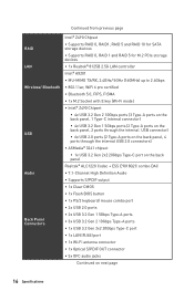
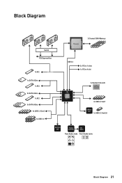
Block Diagram Switch PCI Express Bus 1x M.2 Processor 2 Channel DDR4 Memory DMI 3.0 2x PCIe x1 slots 1x PCIe x4 slot 1x SATA 6Gb/s 1x M.2 2x SATA 6Gb/s 1x M.2 3x SATA 6Gb/s 4x USB 3.2 Gen2 6x USB 2.0 1x Realtek 2.5G LAN PCH 4x USB 3.2 Gen1 ASMedia 3241 1x USB 3.2 Gen2x2 NUVOTON 6687 Realtek ALC1220 ESS E9018 Rear Audio Jacks Front Audio Jacks Block Diagram 21
Block Diagram Switch PCI Express Bus 1x M.2 Processor 2 Channel DDR4 Memory DMI 3.0 2x PCIe x1 slots 1x PCIe x4 slot 1x SATA 6Gb/s 1x M.2 2x SATA 6Gb/s 1x M.2 3x SATA 6Gb/s 4x USB 3.2 Gen2 6x USB 2.0 1x Realtek 2.5G LAN PCH 4x USB 3.2 Gen1 ASMedia 3241 1x USB 3.2 Gen2x2 NUVOTON 6687 Realtek ALC1220 ESS E9018 Rear Audio Jacks Front Audio Jacks Block Diagram 21
User Manual
Page 27
... Mode Booting Jumper Thunderbolt Add-on Card Connector TPM Module Connector USB 3.2 Gen 2 Type-C Connector USB 3.2 Gen 1 Connector USB 2.0 Connectors EZ LED Control M.2 Slots (Key M) PCIe Expansion Slots Power Button, Reset Button SATA 6Gb/s Connectors Page 43 36 28 29 40 46 37 45 49 35 38 39 39 50 48...
... Mode Booting Jumper Thunderbolt Add-on Card Connector TPM Module Connector USB 3.2 Gen 2 Type-C Connector USB 3.2 Gen 1 Connector USB 2.0 Connectors EZ LED Control M.2 Slots (Key M) PCIe Expansion Slots Power Button, Reset Button SATA 6Gb/s Connectors Page 43 36 28 29 40 46 37 45 49 35 38 39 39 50 48...
User Manual
Page 30
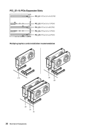
PCI_E1~5: PCIe Expansion Slots PCI_E1: PCIe 3.0 x16 (CPU) PCI_E2: PCIe 3.0 x1 (PCH) PCI_E3: PCIe 3.0 x8 (CPU) PCI_E4: PCIe 3.0 x1 (PCH) PCI_E5: PCIe 3.0 x4 (PCH) Multiple graphics cards installation recommendation x16 x8 x8 x8 x4 x4 30 Overview of Components
PCI_E1~5: PCIe Expansion Slots PCI_E1: PCIe 3.0 x16 (CPU) PCI_E2: PCIe 3.0 x1 (PCH) PCI_E3: PCIe 3.0 x8 (CPU) PCI_E4: PCIe 3.0 x1 (PCH) PCI_E5: PCIe 3.0 x4 (PCH) Multiple graphics cards installation recommendation x16 x8 x8 x8 x4 x4 30 Overview of Components
User Manual
Page 31
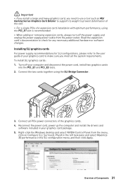
... additional hardware or software changes. ⚠⚠Important ∙∙If you install a large and heavy graphics card, you meet all PCIe power connectors of Components 31 To install SLI graphics cards: 1. Reconnect the power cord, power up the computer and install the drivers ...expansion card's documentation to make sure you need to use a tool such as MSI Gaming Series Graphics Card Bolster to support its weight to prevent deformation of the slot. ∙∙For a single PCIe x16 expansion card installation with optimum performance, using the SLI Bridge Connector. 3. ...
... additional hardware or software changes. ⚠⚠Important ∙∙If you install a large and heavy graphics card, you meet all PCIe power connectors of Components 31 To install SLI graphics cards: 1. Reconnect the power cord, power up the computer and install the drivers ...expansion card's documentation to make sure you need to use a tool such as MSI Gaming Series Graphics Card Bolster to support its weight to prevent deformation of the slot. ∙∙For a single PCIe x16 expansion card installation with optimum performance, using the SLI Bridge Connector. 3. ...
User Manual
Page 32
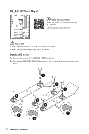
Installing M.2 module 1. Remove the M.2 SHIELD FROZR and remove the protective films from the thermal pads. 1 1 1 M2_1 1 M2_2 1 M2_3 1 2 2 2 32 Overview of M.2 SHIELD FROZR heatsink. 2. M2_1~3: M.2 Slots (Key M) ⚽⚽Video Demonstration Watch the video to learn how to Install M.2 module. Loosen the screws of Components M2_1 http://youtu.be/JCTFABytrYA M2_2 M2_3 ⚠⚠Important ∙∙Intel® RST only supports PCIe M.2 SSD with UEFI ROM. ∙∙Intel® Optane™ Memory Ready for all M.2 slots.
Installing M.2 module 1. Remove the M.2 SHIELD FROZR and remove the protective films from the thermal pads. 1 1 1 M2_1 1 M2_2 1 M2_3 1 2 2 2 32 Overview of M.2 SHIELD FROZR heatsink. 2. M2_1~3: M.2 Slots (Key M) ⚽⚽Video Demonstration Watch the video to learn how to Install M.2 module. Loosen the screws of Components M2_1 http://youtu.be/JCTFABytrYA M2_2 M2_3 ⚠⚠Important ∙∙Intel® RST only supports PCIe M.2 SSD with UEFI ROM. ∙∙Intel® Optane™ Memory Ready for all M.2 slots.

User Manual
Page 34
... installing M.2 SSD in the M2_2 slot. M.2 & SATA combination table Slot Available SATA connectors M2_1 PCIe SATA PCIe SATA PCIe M2_2 M2_3 PCIe PCIe SATA SATA ─ M2_3 slot supports PCIe only SATA1 SATA2 ✓ ✓ ✓ ✓ ✓ ✓ ─ &#... SATA5 SATA6 ─ ─ ─ ─ ✓ ─ ─ ─ ─ ✓ (SATA: M.2 SATA SSD, PCIe: M.2 PCIe SSD, ✓: available, ─: unavailable) SATA ─ 34 Overview of the cable. SATA1~6: SATA 6Gb/s Connectors These connectors are SATA 6Gb/s...
... installing M.2 SSD in the M2_2 slot. M.2 & SATA combination table Slot Available SATA connectors M2_1 PCIe SATA PCIe SATA PCIe M2_2 M2_3 PCIe PCIe SATA SATA ─ M2_3 slot supports PCIe only SATA1 SATA2 ✓ ✓ ✓ ✓ ✓ ✓ ─ &#... SATA5 SATA6 ─ ─ ─ ─ ✓ ─ ─ ─ ─ ✓ (SATA: M.2 SATA SSD, PCIe: M.2 PCIe SSD, ✓: available, ─: unavailable) SATA ─ 34 Overview of the cable. SATA1~6: SATA 6Gb/s Connectors These connectors are SATA 6Gb/s...
User Manual
Page 66
The month from Sun to set the parameters and behaviors of PCIe, ACPI, integrated peripherals, integrated graphics, USB, power management and Windows . ▶▶PCIe/PCI Sub-system Settings sub-menu Sets PCI, PCI express interface protocol and latency timer. ▶▶ACPI Settings sub-menu Sets ACPI parameters of ...
The month from Sun to set the parameters and behaviors of PCIe, ACPI, integrated peripherals, integrated graphics, USB, power management and Windows . ▶▶PCIe/PCI Sub-system Settings sub-menu Sets PCI, PCI express interface protocol and latency timer. ▶▶ACPI Settings sub-menu Sets ACPI parameters of ...
User Manual
Page 79
... at the byte level and also stripe error correction information. This results in this step If you are only using NVMe PCIe SSDs, go to BIOS > SETTINGS > Advanced > Integrated Peripherals > M2_x Pcie Storage Remapping and change setting to enter BIOS Setup menu. 6. Enabling Intel® Rapid Storage Technology 1. If you are using...
... at the byte level and also stripe error correction information. This results in this step If you are only using NVMe PCIe SSDs, go to BIOS > SETTINGS > Advanced > Integrated Peripherals > M2_x Pcie Storage Remapping and change setting to enter BIOS Setup menu. 6. Enabling Intel® Rapid Storage Technology 1. If you are using...

