User Manual
Page 1
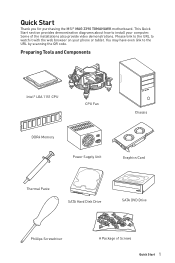
Quick Start Thank you for purchasing the MSI® MAG Z390 TOMAHAWK motherboard. This Quick Start section provides demonstration diagrams about how to install your phone or tablet. Some of Screws Quick Start 1 Preparing Tools and Components Intel® LGA 1151 CPU CPU Fan Chassis DDR4 Memory Power Supply Unit Graphics Card Thermal Paste SATA Hard Disk Drive...
Quick Start Thank you for purchasing the MSI® MAG Z390 TOMAHAWK motherboard. This Quick Start section provides demonstration diagrams about how to install your phone or tablet. Some of Screws Quick Start 1 Preparing Tools and Components Intel® LGA 1151 CPU CPU Fan Chassis DDR4 Memory Power Supply Unit Graphics Card Thermal Paste SATA Hard Disk Drive...

User Manual
Page 11
... 9 Power On...10 Specifications...13 Package contents 18 Block Diagram ...19 Rear I/O Panel ...20 LAN Port LED Status Table 20 Audio Ports Configuration 20 Realtek Audio Console 21 Overview of Components 23 CPU Socket ...25 DIMM Slots...26 PCI_E1~5: PCIe Expansion Slots 27 M2_1~2: M.2 Slots ...(Key M 28 SATA1~6: SATA 6Gb/s Connectors 29 CPU_PWR1~2, ATX_PWR1: Power Connectors 31 JFP1, JFP2: Front Panel Connectors 32 JAUD1: ...
... 9 Power On...10 Specifications...13 Package contents 18 Block Diagram ...19 Rear I/O Panel ...20 LAN Port LED Status Table 20 Audio Ports Configuration 20 Realtek Audio Console 21 Overview of Components 23 CPU Socket ...25 DIMM Slots...26 PCI_E1~5: PCIe Expansion Slots 27 M2_1~2: M.2 Slots ...(Key M 28 SATA1~6: SATA 6Gb/s Connectors 29 CPU_PWR1~2, ATX_PWR1: Power Connectors 31 JFP1, JFP2: Front Panel Connectors 32 JAUD1: ...
User Manual
Page 15
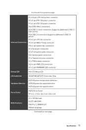
... 24-pin ATX main power connector y 1x 8-pin ATX 12V power connector y 1x 4-pin ATX 12V power connector y 6x SATA 6Gb/s connectors y 2x USB 3.1 Gen1 connectors (supports additional 4 USB 3.1 Gen1 ports) y 2x USB 2.0 connectors (supports additional 4 USB 2.0 ports) y 1x 4-pin CPU fan connector y 1x ...y 1x 3-pin RAINBOW LED connector Debug LED y 4x EZ Debug LED I/O Controller NUVOTON NCT6797 Controller Chip Hardware Monitor y CPU/System temperature detection y CPU/System fan speed detection y CPU/System fan speed control Form Factor y ATX Form Factor y 9.6 in . (24.3 cm x 30.4 cm) BIOS ...
... 24-pin ATX main power connector y 1x 8-pin ATX 12V power connector y 1x 4-pin ATX 12V power connector y 6x SATA 6Gb/s connectors y 2x USB 3.1 Gen1 connectors (supports additional 4 USB 3.1 Gen1 ports) y 2x USB 2.0 connectors (supports additional 4 USB 2.0 ports) y 1x 4-pin CPU fan connector y 1x ...y 1x 3-pin RAINBOW LED connector Debug LED y 4x EZ Debug LED I/O Controller NUVOTON NCT6797 Controller Chip Hardware Monitor y CPU/System temperature detection y CPU/System fan speed detection y CPU/System fan speed control Form Factor y ATX Form Factor y 9.6 in . (24.3 cm x 30.4 cm) BIOS ...
User Manual
Page 17
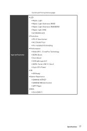
CrossFire Technology ƒ DDR4 Boost ƒ Core Boost ƒ USB with type A+C ƒ INTEL Turbo USB 3.1 Gen 2 ƒ 8-pin CPU Power y VR ƒ VR Ready y Gamer Experience ƒ GAMING HOTKEY ƒ GAMING MOUSE Control ƒ APP Player y BIOS ƒ Click BIOS 5 Specifications 17 Special ...
CrossFire Technology ƒ DDR4 Boost ƒ Core Boost ƒ USB with type A+C ƒ INTEL Turbo USB 3.1 Gen 2 ƒ 8-pin CPU Power y VR ƒ VR Ready y Gamer Experience ƒ GAMING HOTKEY ƒ GAMING MOUSE Control ƒ APP Player y BIOS ƒ Click BIOS 5 Specifications 17 Special ...
User Manual
Page 24
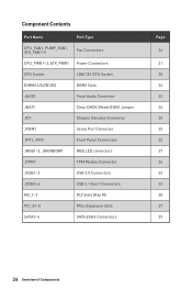
Component Contents Port Name Port Type CPU_FAN1, PUMP_FAN1, SYS_FAN1~5 Fan Connectors CPU_PWR1~2, ATX_PWR1 Power Connectors CPU Socket LGA1151 CPU Socket DIMMA1/A2/B1/B2 DIMM Slots JAUD1 Front Audio Connector JBAT1 Clear CMOS (Reset BIOS) Jumper JCI1 Chassis Intrusion Connector JCOM1 Serial Port Connector ...
Component Contents Port Name Port Type CPU_FAN1, PUMP_FAN1, SYS_FAN1~5 Fan Connectors CPU_PWR1~2, ATX_PWR1 Power Connectors CPU Socket LGA1151 CPU Socket DIMMA1/A2/B1/B2 DIMM Slots JAUD1 Front Audio Connector JBAT1 Clear CMOS (Reset BIOS) Jumper JCI1 Chassis Intrusion Connector JCOM1 Serial Port Connector ...
User Manual
Page 25
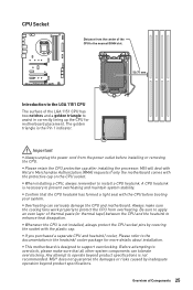
... is designed to support overclocking. MSI will deal with Return Merchandise Authorization (RMA) requests if only the motherboard comes with the CPU before installing or removing the CPU. A CPU heatsink is not installed, always protect the CPU socket pins by inadequate operation beyond... product specifications is not recommended. Important y Always unplug the power cord from the power outlet before booting your ...
... is designed to support overclocking. MSI will deal with Return Merchandise Authorization (RMA) requests if only the motherboard comes with the CPU before installing or removing the CPU. A CPU heatsink is not installed, always protect the CPU socket pins by inadequate operation beyond... product specifications is not recommended. Important y Always unplug the power cord from the power outlet before booting your ...
User Manual
Page 27
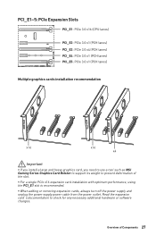
... and unplug the power supply power cable from the power outlet. Read the expansion card's documentation to prevent deformation of Components 27 Overview of the slot. y For a single PCIe x16 expansion card installation with optimum performance, using the PCI_E1 slot is recommended. PCI_E1~5: PCIe Expansion Slots PCI_E1: PCIe 3.0 x16 (CPU lanes) PCI_E2: PCIe 3.0 x1...
... and unplug the power supply power cable from the power outlet. Read the expansion card's documentation to prevent deformation of Components 27 Overview of the slot. y For a single PCIe x16 expansion card installation with optimum performance, using the PCI_E1 slot is recommended. PCI_E1~5: PCIe Expansion Slots PCI_E1: PCIe 3.0 x16 (CPU lanes) PCI_E2: PCIe 3.0 x1...
User Manual
Page 48
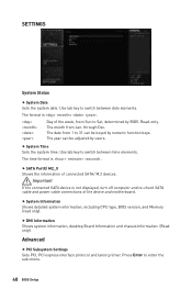
Read-only. Important If the connected SATA device is not displayed, turn off computer and re-check SATA cable and power cable connections of connected SATA/ M.2 devices. Advanced f PCI Subsystem Settings Sets PCI, PCI express interface protocol and latency timer. through Dec. Press Enter to 31 ... tab key to switch between date elements. The date from 1 to enter the sub-menu. 48 BIOS Setup f System Information Shows detailed system information, including CPU type, BIOS version, and Memory (read only).
Read-only. Important If the connected SATA device is not displayed, turn off computer and re-check SATA cable and power cable connections of connected SATA/ M.2 devices. Advanced f PCI Subsystem Settings Sets PCI, PCI express interface protocol and latency timer. through Dec. Press Enter to 31 ... tab key to switch between date elements. The date from 1 to enter the sub-menu. 48 BIOS Setup f System Information Shows detailed system information, including CPU type, BIOS version, and Memory (read only).
User Manual
Page 49
... [Disabled] Sets UEFI network stack for detailed settings. fCPU Over Temperature Alert [Auto] Enables or disables the CPU overheating alert when CPU temperature is over 80 degrees centigrade. f ACPI Settings Sets ACPI parameters of the onboard Power LED. [Dual Color] The power LED turns to another color to indicate the S3 state. [Blinking] The...
... [Disabled] Sets UEFI network stack for detailed settings. fCPU Over Temperature Alert [Auto] Enables or disables the CPU overheating alert when CPU temperature is over 80 degrees centigrade. f ACPI Settings Sets ACPI parameters of the onboard Power LED. [Dual Color] The power LED turns to another color to indicate the S3 state. [Blinking] The...
User Manual
Page 59
.... This item appears when the installed CPU supports this function. [Enabled] Enables this function to boost CPU performance. Please note the overclocking behavior is not guaranteed. f Misc Setting* Press Enter, + or - It can decrease average power consumption and average heat production. [Disabled...] Disables EIST. You may overclock the CPU by choosing optimized memory preset. f CPU Base Clock (MHz) [Default] Sets the CPU Base clock. Read-only. key to open or close the...
.... This item appears when the installed CPU supports this function. [Enabled] Enables this function to boost CPU performance. Please note the overclocking behavior is not guaranteed. f Misc Setting* Press Enter, + or - It can decrease average power consumption and average heat production. [Disabled...] Disables EIST. You may overclock the CPU by choosing optimized memory preset. f CPU Base Clock (MHz) [Default] Sets the CPU Base clock. Read-only. key to open or close the...
User Manual
Page 60
...setup some protecting conditions about voltage/ current/ temputure for new devices. If set to Auto, BIOS will set these voltages automatically or you to CPU. f CPU Specifications Press Enter to enter the sub-menu. fCPU Technology Support Press Enter to enter the sub-menu. The sub-menu shows the... key features of installed CPU. f MEMORY-Z Press Enter to enter the sub-menu. f DigitALL Power Press Enter to enter the sub-menu. If set to Auto, BIOS will set these voltages automatically or you to...
...setup some protecting conditions about voltage/ current/ temputure for new devices. If set to Auto, BIOS will set these voltages automatically or you to CPU. f CPU Specifications Press Enter to enter the sub-menu. fCPU Technology Support Press Enter to enter the sub-menu. The sub-menu shows the... key features of installed CPU. f MEMORY-Z Press Enter to enter the sub-menu. f DigitALL Power Press Enter to enter the sub-menu. If set to Auto, BIOS will set these voltages automatically or you to...
User Manual
Page 62
The options of system and reduce CPU power consumption accordingly. [Disabled] Disable this function. It can decrease average power consumption and average heat production. [Disabled] Disables EIST. fPackage C State limit [Auto] This item allows you to select a CPU C-state level for Normal mode and appears when a CPU that support Turbo Boost is idle. fEIST [Enabled] Enables...
The options of system and reduce CPU power consumption accordingly. [Disabled] Disable this function. It can decrease average power consumption and average heat production. [Disabled] Disables EIST. fPackage C State limit [Auto] This item allows you to select a CPU C-state level for Normal mode and appears when a CPU that support Turbo Boost is idle. fEIST [Enabled] Enables...
User Manual
Page 63
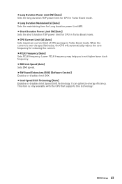
...ciency. fSW Guard Extensions (SGX) [Software Control] Enables or disables Intel SGX. BIOS Setup 63 fShort Duration Power Limit (W) [Auto] Sets the short duration TDP power limit for CPU in Turbo Boost mode. Lower FCLK frequency may help you to set higher base clock frequency. This item ...is over the specified value, the CPU will automatically reduce the core frequency for Long duration power Limit(W). fIntel Speed Shift Technology [Auto] Enables or disables Intel Speed Shift Technology. fLong Duration Maintained (s) [Auto...
...ciency. fSW Guard Extensions (SGX) [Software Control] Enables or disables Intel SGX. BIOS Setup 63 fShort Duration Power Limit (W) [Auto] Sets the short duration TDP power limit for CPU in Turbo Boost mode. Lower FCLK frequency may help you to set higher base clock frequency. This item ...is over the specified value, the CPU will automatically reduce the core frequency for Long duration power Limit(W). fIntel Speed Shift Technology [Auto] Enables or disables Intel Speed Shift Technology. fLong Duration Maintained (s) [Auto...


