User Manual
Page 1
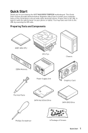
... watch it with the web browser on your computer. Please link to the URL to the URL by scanning the QR code. Quick Start Thank you for purchasing the MSI® MAG B550 TORPEDO motherboard. Some of Screws Quick Start 1 Preparing Tools and Components AMD® AM4 CPU CPU Fan DDR4 Memory Power Supply Unit Chassis Graphics Card Thermal Paste SATA Hard Disk Drive SATA DVD Drive Phillips Screwdriver A Package of the installations also provide video demonstrations.
... watch it with the web browser on your computer. Please link to the URL to the URL by scanning the QR code. Quick Start Thank you for purchasing the MSI® MAG B550 TORPEDO motherboard. Some of Screws Quick Start 1 Preparing Tools and Components AMD® AM4 CPU CPU Fan DDR4 Memory Power Supply Unit Chassis Graphics Card Thermal Paste SATA Hard Disk Drive SATA DVD Drive Phillips Screwdriver A Package of the installations also provide video demonstrations.

User Manual
Page 13
... Quick Start ...1 Preparing Tools and Components 1 Safety Information 2 Installing a Processor 3 Installing DDR4 memory 5 Connecting the Front Panel Header 6 Installing the Motherboard 7 Connecting the Power Connectors 8 Installing SATA Drives 9 Installing a Graphics Card 10 Connecting Peripheral Devices 11 Power On...12 Specifications...15 Package contents 20 Block Diagram ...21 Rear I/O Panel...22 LAN Port LED Status Table 22 Audio Ports Configuration 22 Realtek Audio Console 23 Overview of Components 25 Processor Socket 27 DIMM Slots...28 PCI_E1~4: PCIe Expansion Slots 29...
... Quick Start ...1 Preparing Tools and Components 1 Safety Information 2 Installing a Processor 3 Installing DDR4 memory 5 Connecting the Front Panel Header 6 Installing the Motherboard 7 Connecting the Power Connectors 8 Installing SATA Drives 9 Installing a Graphics Card 10 Connecting Peripheral Devices 11 Power On...12 Specifications...15 Package contents 20 Block Diagram ...21 Rear I/O Panel...22 LAN Port LED Status Table 22 Audio Ports Configuration 22 Realtek Audio Console 23 Overview of Components 25 Processor Socket 27 DIMM Slots...28 PCI_E1~4: PCIe Expansion Slots 29...

User Manual
Page 14
... RGB LED connectors 40 EZ Debug LED...41 LED_SW1: EZ LED Control 41 Installing OS, Drivers & Utilities 42 Installing Windows® 10 42 Installing Drivers 42 Installing Utilities 42 UEFI BIOS...43 BIOS Setup...44 Entering BIOS Setup 44 Resetting BIOS...45 Updating BIOS...45 EZ Mode ...47 Advanced Mode ...50 SETTINGS Menu 51 OC Menu...53 M-FLASH Menu ...55 OC PROFILE Menu 56 HARDWARE MONITOR Menu 57 AMD RAID Configuration 59 Enabling RAIDXpert2 Configuration Utility 59 Initializing Disks 60 Creating Arrays...61 Deleting Arrays ...62 Installing RAID Driver 63 Troubleshooting 64...
... RGB LED connectors 40 EZ Debug LED...41 LED_SW1: EZ LED Control 41 Installing OS, Drivers & Utilities 42 Installing Windows® 10 42 Installing Drivers 42 Installing Utilities 42 UEFI BIOS...43 BIOS Setup...44 Entering BIOS Setup 44 Resetting BIOS...45 Updating BIOS...45 EZ Mode ...47 Advanced Mode ...50 SETTINGS Menu 51 OC Menu...53 M-FLASH Menu ...55 OC PROFILE Menu 56 HARDWARE MONITOR Menu 57 AMD RAID Configuration 59 Enabling RAIDXpert2 Configuration Utility 59 Initializing Disks 60 Creating Arrays...61 Deleting Arrays ...62 Installing RAID Driver 63 Troubleshooting 64...
User Manual
Page 18
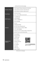
... page 18 Specifications Continued from previous page Hardware Monitor Form Factor BIOS Features Software Dragon Center Features ∙∙CPU/ System/ Chipset temperature detection ∙∙CPU/ System/ Pump fan speed detection ∙∙CPU/ System/ Pump fan speed control ∙∙ATX Form Factor ∙∙12 in . (30.5 cm x 24.4 cm) ∙∙1x 256 Mb flash ∙∙UEFI AMI BIOS ∙∙ACPI 6.0, SMBIOS 2.8 ∙...
... page 18 Specifications Continued from previous page Hardware Monitor Form Factor BIOS Features Software Dragon Center Features ∙∙CPU/ System/ Chipset temperature detection ∙∙CPU/ System/ Pump fan speed detection ∙∙CPU/ System/ Pump fan speed control ∙∙ATX Form Factor ∙∙12 in . (30.5 cm x 24.4 cm) ∙∙1x 256 Mb flash ∙∙UEFI AMI BIOS ∙∙ACPI 6.0, SMBIOS 2.8 ∙...

User Manual
Page 38
Keep Data (default) Clear CMOS/ Reset BIOS Resetting BIOS to clear the CMOS memory. Remove the jumper cap from a battery located on the computer. 38 Overview of Components Plug the power cord and Power on the motherboard to short JBAT1 for about 5-10 seconds. 3. Power off the computer and unplug the power cord. 2. If you want to clear the system configuration, set the jumpers to default values 1. Use a jumper cap to save system configuration data. JBAT1: Clear CMOS (Reset BIOS) Jumper There is CMOS memory onboard that is external powered from JBAT1. 4.
Keep Data (default) Clear CMOS/ Reset BIOS Resetting BIOS to clear the CMOS memory. Remove the jumper cap from a battery located on the computer. 38 Overview of Components Plug the power cord and Power on the motherboard to short JBAT1 for about 5-10 seconds. 3. Power off the computer and unplug the power cord. 2. If you want to clear the system configuration, set the jumpers to default values 1. Use a jumper cap to save system configuration data. JBAT1: Clear CMOS (Reset BIOS) Jumper There is CMOS memory onboard that is external powered from JBAT1. 4.

User Manual
Page 40
... JRAINBOW connector provide different voltages, and connecting the 5V LED strip to the JRGB connector will result in damage to the LED strip. ⚠⚠Important ∙∙The JRAINBOW connector supports up to 200 LEDs. ∙∙Always turn off the power supply and unplug the power cord from the power outlet before installing or removing the RGB LED strip. ∙∙Please use MSI's software to 75 LEDs WS2812B...
... JRAINBOW connector provide different voltages, and connecting the 5V LED strip to the JRGB connector will result in damage to the LED strip. ⚠⚠Important ∙∙The JRAINBOW connector supports up to 200 LEDs. ∙∙Always turn off the power supply and unplug the power cord from the power outlet before installing or removing the RGB LED strip. ∙∙Please use MSI's software to 75 LEDs WS2812B...
User Manual
Page 42
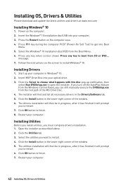
... case. 4. Press F11 key during the computer POST (Power-On Self Test) to install Windows® 10. Select the Windows® 10 installation disc/USB from the Windows Control Panel, you must complete drivers installation. 1. Follow the instructions on the screen to get into Boot Menu. 5. If you turn off the AutoPlay feature from the Boot Menu. 6. The drivers installation will then be in progress, after it has finished it will find and list...
... case. 4. Press F11 key during the computer POST (Power-On Self Test) to install Windows® 10. Select the Windows® 10 installation disc/USB from the Windows Control Panel, you must complete drivers installation. 1. Follow the instructions on the screen to get into Boot Menu. 5. If you turn off the AutoPlay feature from the Boot Menu. 6. The drivers installation will then be in progress, after it has finished it will find and list...
User Manual
Page 45
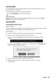
Insert the USB flash drive that matches your motherboard model from MSI website. Select a BIOS file to the Clear CMOS jumper section for BIOS update. ▪▪Reboot and press Del key during POST and click on Yes to load optimized defaults. ∙∙Short the Clear CMOS jumper on Yes to enter BIOS. UEFI BIOS 45 Updating BIOS Updating BIOS with M-FLASH Before updating: Please download the latest BIOS file that contains the update file into the USB flash drive. Updating BIOS: 1. After the flashing process is off before clearing CMOS data. Please refer...
Insert the USB flash drive that matches your motherboard model from MSI website. Select a BIOS file to the Clear CMOS jumper section for BIOS update. ▪▪Reboot and press Del key during POST and click on Yes to load optimized defaults. ∙∙Short the Clear CMOS jumper on Yes to enter BIOS. UEFI BIOS 45 Updating BIOS Updating BIOS with M-FLASH Before updating: Please download the latest BIOS file that contains the update file into the USB flash drive. Updating BIOS: 1. After the flashing process is off before clearing CMOS data. Please refer...
User Manual
Page 46
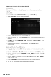
... MSI.ROM file into the Flash BIOS Port on Scan button to flash BIOS, and the LED starts flashing. 6. Updating the BIOS with Flash BIOS Button 1. Select the BIOS file and click on Advance button. 3. Click Next and choose In Windows mode. The LED will be turned off when the process is 100% completed, the system will restart automatically. Select Live Update and click on Download icon to install CPU and memory.) 4. After the flashing process is completed. 46 UEFI BIOS Connect the power supply...
... MSI.ROM file into the Flash BIOS Port on Scan button to flash BIOS, and the LED starts flashing. 6. Updating the BIOS with Flash BIOS Button 1. Select the BIOS file and click on Advance button. 3. Click Next and choose In Windows mode. The LED will be turned off when the process is 100% completed, the system will restart automatically. Select Live Update and click on Download icon to install CPU and memory.) 4. After the flashing process is completed. 46 UEFI BIOS Connect the power supply...

User Manual
Page 48
... the CPU/ DDR speed, CPU/ MB temperature, MB/ CPU type, memory size, CPU/ DDR voltage, BIOS version and build date. ∙∙ Boot device priority bar - click on these functions by percentage. ∙∙ Favorites - enable or disable these buttons. The boot priority from high to low is enabled when the button shows ON . ⚠⚠Important The function buttons will vary with a USB flash drive. ∙∙ Hardware Monitor - click on this button to manually control the fan speed by...
... the CPU/ DDR speed, CPU/ MB temperature, MB/ CPU type, memory size, CPU/ DDR voltage, BIOS version and build date. ∙∙ Boot device priority bar - click on these functions by percentage. ∙∙ Favorites - enable or disable these buttons. The boot priority from high to low is enabled when the button shows ON . ⚠⚠Important The function buttons will vary with a USB flash drive. ∙∙ Hardware Monitor - click on this button to manually control the fan speed by...

User Manual
Page 50
...;BOARD EXPLORER - provides the way to be configured. 50 UEFI BIOS provides BIOS setting items and information to update BIOS with a USB flash drive. ▪▪OC PROFILE - allows you to set the speeds of fans and monitor voltages of installed devices on this motherboard. ∙∙ Menu display - Advanced Mode Press Setup Mode switch or F7 function key can switch between EZ Mode and Advanced Mode in BIOS setup. BIOS menu selection BIOS menu selection Menu display ∙∙ BIOS menu selection - the following options are available: ▪▪SETTINGS...
...;BOARD EXPLORER - provides the way to be configured. 50 UEFI BIOS provides BIOS setting items and information to update BIOS with a USB flash drive. ▪▪OC PROFILE - allows you to set the speeds of fans and monitor voltages of installed devices on this motherboard. ∙∙ Menu display - Advanced Mode Press Setup Mode switch or F7 function key can switch between EZ Mode and Advanced Mode in BIOS setup. BIOS menu selection BIOS menu selection Menu display ∙∙ BIOS menu selection - the following options are available: ▪▪SETTINGS...

User Manual
Page 51
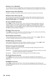
... is not displayed, turn off computer and re-check SATA/ M.2 cable and power cable connections of the device and motherboard. ▶▶System Information Shows detailed system information, including CPU type, BIOS version, and Memory (read only). ▶▶DMI Information Shows system information, desktop board information and chassis information. ▶▶Advanced sub-menu The Advanced sub-menu allows you to enter the sub-menu. ▶▶ACPI Settings Sets ACPI parameters of onboard power LED behaviors...
... is not displayed, turn off computer and re-check SATA/ M.2 cable and power cable connections of the device and motherboard. ▶▶System Information Shows detailed system information, including CPU type, BIOS version, and Memory (read only). ▶▶DMI Information Shows system information, desktop board information and chassis information. ▶▶Advanced sub-menu The Advanced sub-menu allows you to enter the sub-menu. ▶▶ACPI Settings Sets ACPI parameters of onboard power LED behaviors...
User Manual
Page 52
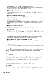
...-menu Sets system wake up behaviors for different sleep modes. ▶▶Secure Erase+ Enables or disables Secure Erase+ function. You also can enter the setup and OS without changes. 52 UEFI BIOS Once the password is being disabled. A message will replace any previous set the administrator password and the user password for optimum system. You can support this function. ▶▶Realtek PCIe GbE Family Controller (MAC sub-menu This sub-menu shows driver...
...-menu Sets system wake up behaviors for different sleep modes. ▶▶Secure Erase+ Enables or disables Secure Erase+ function. You also can enter the setup and OS without changes. 52 UEFI BIOS Once the password is being disabled. A message will replace any previous set the administrator password and the user password for optimum system. You can support this function. ▶▶Realtek PCIe GbE Family Controller (MAC sub-menu This sub-menu shows driver...
User Manual
Page 53
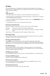
...;Adjusted DRAM Frequency Shows the adjusted DRAM frequency. Note: We use GAME BOOST function for easy overclocking. ∙∙The BIOS items in OC menu will be changed if the processor supports this function. ▶▶DRAM Frequency [Auto] Sets the DRAM frequency. This item can set the parameters about CPU power/ current. User can only be available when the installed processor, memory modules and motherboard support this function. ▶▶Advanced CPU Configuration Press Enter to configure the frequencies and voltages...
...;Adjusted DRAM Frequency Shows the adjusted DRAM frequency. Note: We use GAME BOOST function for easy overclocking. ∙∙The BIOS items in OC menu will be changed if the processor supports this function. ▶▶DRAM Frequency [Auto] Sets the DRAM frequency. This item can set the parameters about CPU power/ current. User can only be available when the installed processor, memory modules and motherboard support this function. ▶▶Advanced CPU Configuration Press Enter to configure the frequencies and voltages...
User Manual
Page 54
... memory has been replaced. [Enabled] [Disabled] The system will restore the last available settings. User can set the voltages related to issue a warning message during boot and then you can set the voltages related to CPU. If it occurs, please clear the CMOS data and restore the default settings. (Refer to the Clear CMOS jumper section to clear the CMOS data, and enter the BIOS to load the default settings.) ▶▶DigitALL Power sub-menu Press Enter to enter...
... memory has been replaced. [Enabled] [Disabled] The system will restore the last available settings. User can set the voltages related to issue a warning message during boot and then you can set the voltages related to CPU. If it occurs, please clear the CMOS data and restore the default settings. (Refer to the Clear CMOS jumper section to clear the CMOS data, and enter the BIOS to load the default settings.) ▶▶DigitALL Power sub-menu Press Enter to enter...

User Manual
Page 55
... update BIOS with a USB flash drive. Click on M-FLASH tab, a demand message will appear after rebooting. 4. The system will enter the flash mode and a file selection menu will be prompted. Click on Yes to perform the BIOS update process. 5. After the flashing process is 100% completed, the system will reboot automatically. Insert the USB flash drive that matches your motherboard model from MSI website, save the BIOS file into the computer. 2. Select a BIOS file...
... update BIOS with a USB flash drive. Click on M-FLASH tab, a demand message will appear after rebooting. 4. The system will enter the flash mode and a file selection menu will be prompted. Click on Yes to perform the BIOS update process. 5. After the flashing process is 100% completed, the system will reboot automatically. Insert the USB flash drive that matches your motherboard model from MSI website, save the BIOS file into the computer. 2. Select a BIOS file...
User Manual
Page 59
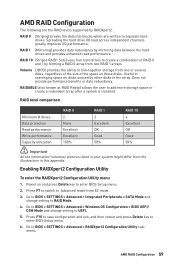
RAID 10 (Striped RAID1 Sets) uses four hard drives to RAID Mode. 4. Enabling RAIDXpert2 Configuration Utility To enter the RAIDXpert2 Configuration Utility menu 1. Go to BIOS > SETTINGS > Advanced > Windows OS Configuration > BIOS UEFI/ CSM Mode and change setting to create a combination of the space on those disks. RAIDABLE (also known as RAID Ready) allows the user to enter BIOS Setup menu. 6. Press F10 to save configuration and exit, and then reboot and press Delete key to add more storage space or create a redundant array...
RAID 10 (Striped RAID1 Sets) uses four hard drives to RAID Mode. 4. Enabling RAIDXpert2 Configuration Utility To enter the RAIDXpert2 Configuration Utility menu 1. Go to BIOS > SETTINGS > Advanced > Windows OS Configuration > BIOS UEFI/ CSM Mode and change setting to create a combination of the space on those disks. RAIDABLE (also known as RAID Ready) allows the user to enter BIOS Setup menu. 6. Press F10 to save configuration and exit, and then reboot and press Delete key to add more storage space or create a redundant array...
User Manual
Page 63
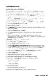
... operating system installation, after the RAID volume is formatted, and Windows setup starts copying files. Navigate to RAID Mode in BIOS 2. Select the (rcraid.inf) driver, click Next. 8. Insert the MSI Driver Disc into the optical drive. admin 9. When prompted, insert the USB flash drive with the new credentials. exe from the Windows Control Panel, you to restart, click OK button to finish. 7. Under the Drivers/Software tab, check the AMD RAID Drivers check-box...
... operating system installation, after the RAID volume is formatted, and Windows setup starts copying files. Navigate to RAID Mode in BIOS 2. Select the (rcraid.inf) driver, click Next. 8. Insert the MSI Driver Disc into the optical drive. admin 9. When prompted, insert the USB flash drive with the new credentials. exe from the Windows Control Panel, you to restart, click OK button to finish. 7. Under the Drivers/Software tab, check the AMD RAID Drivers check-box...

User Manual
Page 64
... the monitor is not on. ∙∙Connect the AC power cord to JFP1 pin header properly. ∙∙Verify the Clear CMOS jumper JBAT1 is turned on the motherboard rear IO panel. ∙∙Remove secondary speakers/ headphones, HDMI cables, USB audio devices. ∙∙Test with another known working LAN cable. The power is turned on. ∙∙Select different inputs on the motherboard rear IO panel. Troubleshooting Before sending the motherboard for motherboard with Dual BIOS) 64 Troubleshooting
... the monitor is not on. ∙∙Connect the AC power cord to JFP1 pin header properly. ∙∙Verify the Clear CMOS jumper JBAT1 is turned on the motherboard rear IO panel. ∙∙Remove secondary speakers/ headphones, HDMI cables, USB audio devices. ∙∙Test with another known working LAN cable. The power is turned on. ∙∙Select different inputs on the motherboard rear IO panel. Troubleshooting Before sending the motherboard for motherboard with Dual BIOS) 64 Troubleshooting
User Manual
Page 68
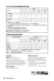
... ○ 備考1. The MSI logo used is expressed or implied. MSI reserves the right to make changes to accuracy or completeness is a registered trademark of their respective owners. Revision History Version 3.0, 2020/09, First release. yy Visit the MSI website for further guidance. All other...help resources for technical guide, BIOS updates, driver updates, and other marks and names mentioned may be obtained from the user guide, please contact your product at: http://register.msi.com 68 Regulatory Notices Technical Support If a problem arises with your system...
... ○ 備考1. The MSI logo used is expressed or implied. MSI reserves the right to make changes to accuracy or completeness is a registered trademark of their respective owners. Revision History Version 3.0, 2020/09, First release. yy Visit the MSI website for further guidance. All other...help resources for technical guide, BIOS updates, driver updates, and other marks and names mentioned may be obtained from the user guide, please contact your product at: http://register.msi.com 68 Regulatory Notices Technical Support If a problem arises with your system...


