
User Guide
Page 2
... own expense. Notice 2 Shielded interface cables and A.C. Operation of the FCC rules. VOIR LA NOTICE D'INSTALLATION AVANT DE RACCORDER AU RESEAU. Micro-Star International MS-6734 This device complies with the instruction manual, may cause harmful interference to comply with the emission limits. Operation is subject to the following two conditions...
... own expense. Notice 2 Shielded interface cables and A.C. Operation of the FCC rules. VOIR LA NOTICE D'INSTALLATION AVANT DE RACCORDER AU RESEAU. Micro-Star International MS-6734 This device complies with the instruction manual, may cause harmful interference to comply with the emission limits. Operation is subject to the following two conditions...

User Guide
Page 7
The KM4M / KM4AM v1.x Micro-ATX mainboard is based on VIA® Apollo KM400/400A North Bridge & VT8235/8237 South Bridge chipset for purchasing the KM4M / KM4AM (MS-6734 v1.x) MicroATX mainboard. Getting Started Getting Started Thank you for optimal system efficiency. Designed to fit the advanced AMD® Athlon™, Athlon™ XP or Duron™ processors, the KM4M / KM4AM delivers a high performance and professional desktop platform solution. 1-1
The KM4M / KM4AM v1.x Micro-ATX mainboard is based on VIA® Apollo KM400/400A North Bridge & VT8235/8237 South Bridge chipset for purchasing the KM4M / KM4AM (MS-6734 v1.x) MicroATX mainboard. Getting Started Getting Started Thank you for optimal system efficiency. Designed to fit the advanced AMD® Athlon™, Athlon™ XP or Duron™ processors, the KM4M / KM4AM delivers a high performance and professional desktop platform solution. 1-1

User Guide
Page 8
Supports DDR200/266/333/400* (*for KM4M) (For the latest information about CPU, please visit http://www.msi.com.tw/program/products/mainboard/mbd/pro_mbd_cpu_support.php) Chipset h VIA® KM400/400A North Bridge - Integrated Direct Sound AC97 audio - Integrated USB 2.0 controller *... on the VT8235/8237 chipset provides IDE HDD/CD-ROM with housing 1-2 Dual channel Ultra DMA 33/66/100/133 master mode EIDE controller - MS-6734 M-ATX Mainboard Mainboard Specifications CPU h Supports Socket A (Socket-462) for AMD® /Athlon™ XP /Sempron™ processors h Supports AMD Athlon XP ...
Supports DDR200/266/333/400* (*for KM4M) (For the latest information about CPU, please visit http://www.msi.com.tw/program/products/mainboard/mbd/pro_mbd_cpu_support.php) Chipset h VIA® KM400/400A North Bridge - Integrated Direct Sound AC97 audio - Integrated USB 2.0 controller *... on the VT8235/8237 chipset provides IDE HDD/CD-ROM with housing 1-2 Dual channel Ultra DMA 33/66/100/133 master mode EIDE controller - MS-6734 M-ATX Mainboard Mainboard Specifications CPU h Supports Socket A (Socket-462) for AMD® /Athlon™ XP /Sempron™ processors h Supports AMD Athlon XP ...

User Guide
Page 10
ATX Power Supply FDD1 MS-6734 M-ATX Mainboard Mainboard Layout Top : mouse Bottom: keyboard T:1394 port (Optional) B:USB ports SOCKET 462 CPUFA1 Winbond 83697HF BIOS Top : LPT Bottom: COM A VGA port JPW1 T: RJ45 LAN jack B: USB ports T:Line-In M:Line-Out B:Mic VIA VT6103 VIA VT6307 (Optional) J1394_2 (Optional) Codec JAUD1 VIA KM400/400A SYSFA1 AGP Slot PCI Slot 1 BATT + PCI Slot 2 PCI Slot 3 J1394_1 (Optional) JCD1 JSP1 VIA VT8235/8237 SW1 SW2 JUSB2 JUSB3(Optional) JFP1 JFP2 MS-6734 v1.X M-ATX Mainboard DIMM 1 IDE 1 IDE 2 1-4
ATX Power Supply FDD1 MS-6734 M-ATX Mainboard Mainboard Layout Top : mouse Bottom: keyboard T:1394 port (Optional) B:USB ports SOCKET 462 CPUFA1 Winbond 83697HF BIOS Top : LPT Bottom: COM A VGA port JPW1 T: RJ45 LAN jack B: USB ports T:Line-In M:Line-Out B:Mic VIA VT6103 VIA VT6307 (Optional) J1394_2 (Optional) Codec JAUD1 VIA KM400/400A SYSFA1 AGP Slot PCI Slot 1 BATT + PCI Slot 2 PCI Slot 3 J1394_1 (Optional) JCD1 JSP1 VIA VT8235/8237 SW1 SW2 JUSB2 JUSB3(Optional) JFP1 JFP2 MS-6734 v1.X M-ATX Mainboard DIMM 1 IDE 1 IDE 2 1-4

User Guide
Page 14
... CPU is likely to move while the lever is properly and completely embedded into the socket and can only fit in the correct orientation. 4. MS-6734 M-ATX Mainboard CPU Installation Procedures for the gold arrow. Open Lever 2. Please note that any violation of the correct installation procedures may cause permanent damages...
... CPU is likely to move while the lever is properly and completely embedded into the socket and can only fit in the correct orientation. 4. MS-6734 M-ATX Mainboard CPU Installation Procedures for the gold arrow. Open Lever 2. Please note that any violation of the correct installation procedures may cause permanent damages...

User Guide
Page 16
... default. To set to operate beyond product specifications. 2-6 BIOS Setup. Any attempt to 100MHz by inadequate operation or beyond product specifications is not recommended. MS-6734 M-ATX Mainboard CPU Clock Frequency Selection through BIOS The hardware configuration for the installed CPU, refer to adjust the CPU clock frequency in Chapter...
... default. To set to operate beyond product specifications. 2-6 BIOS Setup. Any attempt to 100MHz by inadequate operation or beyond product specifications is not recommended. MS-6734 M-ATX Mainboard CPU Clock Frequency Selection through BIOS The hardware configuration for the installed CPU, refer to adjust the CPU clock frequency in Chapter...

User Guide
Page 18
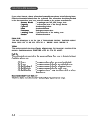
... in the socket. 3. You can barely see the golden finger if the module is deeply inserted in until the golden finger on the slots. MS-6734 M-ATX Mainboard DIMM Module Combination Install at each side of module. Insert the DIMM memory module vertically into the DIMM slot. You can be installed... Memory Suppported Total Memory 64MB~1GB 64MB~1GB 64MB~2GB S: Single Side D: Double Side Installing DDR Modules 1. Memory modules can install either single- Volt Notch MSI Reminds You... or doublesided modules in any order to meet your own needs.
... in the socket. 3. You can barely see the golden finger if the module is deeply inserted in until the golden finger on the slots. MS-6734 M-ATX Mainboard DIMM Module Combination Install at each side of module. Insert the DIMM memory module vertically into the DIMM slot. You can be installed... Memory Suppported Total Memory 64MB~1GB 64MB~1GB 64MB~2GB S: Single Side D: Double Side Installing DDR Modules 1. Memory modules can install either single- Volt Notch MSI Reminds You... or doublesided modules in any order to meet your own needs.

User Guide
Page 20
MS-6734 M-ATX Mainboard Back Panel The back panel provides the following connectors: Mouse IEEE1394 (Optional) Parallel LAN (Optional) Keyboard USB COM VGA USB L-in L-out MIC ...
MS-6734 M-ATX Mainboard Back Panel The back panel provides the following connectors: Mouse IEEE1394 (Optional) Parallel LAN (Optional) Keyboard USB COM VGA USB L-in L-out MIC ...

User Guide
Page 22
... Description GREEN N/C GND GND GND SDA Vertical Sync IEEE1394 Port (Optional) The back panel provides one 9-pin male DIN connector as serial port COM 1. MS-6734 M-ATX Mainboard Serial Port Connector: COM 1 The mainboard offers one standard IEEE 1394 port.
... Description GREEN N/C GND GND GND SDA Vertical Sync IEEE1394 Port (Optional) The back panel provides one 9-pin male DIN connector as serial port COM 1. MS-6734 M-ATX Mainboard Serial Port Connector: COM 1 The mainboard offers one standard IEEE 1394 port.

User Guide
Page 26
... on cable, you must configure second hard drive to the hard disk documentation supplied by hard disk vendors for future BIOS) and other devices. MSI Reminds You... You can connect up to IDE1. IDE1 IDE2 IDE1 (Primary IDE Connector) The first hard drive should always be connected to four... the jumper accordingly. IDE2 (Secondary IDE Connector) IDE2 can connect a Master and a Slave drive. Refer to Slave mode by setting its jumper. MS-6734 M-ATX Mainboard Hard Disk Connectors: IDE1 & IDE2 The mainboard has a 32-bit Enhanced PCI IDE and Ultra DMA 33/66/100/133 controller that provides...
... on cable, you must configure second hard drive to the hard disk documentation supplied by hard disk vendors for future BIOS) and other devices. MSI Reminds You... You can connect up to IDE1. IDE1 IDE2 IDE1 (Primary IDE Connector) The first hard drive should always be connected to four... the jumper accordingly. IDE2 (Secondary IDE Connector) IDE2 can connect a Master and a Slave drive. Refer to Slave mode by setting its jumper. MS-6734 M-ATX Mainboard Hard Disk Connectors: IDE1 & IDE2 The mainboard has a 32-bit Enhanced PCI IDE and Ultra DMA 33/66/100/133 controller that provides...

User Guide
Page 28
... SIGNAL 2 SPK- 4 BUZ+ 6 BUZ- 8 SPK+ CD-In Connector: JCD1 The connector is compliant with Intel® Front Panel I/O Connectivity Design Guide. Do not use. MS-6734 M-ATX Mainboard Front Panel Connectors: JFP1 & JFP2 The mainboard provides two front panel connectors for CD-ROM audio connector. 2-18 R L GND JCD1 Power Power LED...
... SIGNAL 2 SPK- 4 BUZ+ 6 BUZ- 8 SPK+ CD-In Connector: JCD1 The connector is compliant with Intel® Front Panel I/O Connectivity Design Guide. Do not use. MS-6734 M-ATX Mainboard Front Panel Connectors: JFP1 & JFP2 The mainboard provides two front panel connectors for CD-ROM audio connector. 2-18 R L GND JCD1 Power Power LED...

User Guide
Page 30
MS-6734 M-ATX Mainboard IEEE 1394 Connectors: J1394_1 & J1394_2 (Optional) The mainboard provides one or two optional 1394 pin headers J1394_1 and J1394_2 that allow you to connect optional IEEE 1394 ports. 9 1 10 2 J1394_1 / J1394_2 (Optional) Pin Definition PIN SIGNAL PIN 1 TPA+ 2 3 Ground 4 5 TPB+ 6 7 Cable power 8 9 Key (no pin) 10 SIGNAL TPAGround TPBCable power Ground IEEE1394 Bracket (Optional) Foolproof Design 2-20
MS-6734 M-ATX Mainboard IEEE 1394 Connectors: J1394_1 & J1394_2 (Optional) The mainboard provides one or two optional 1394 pin headers J1394_1 and J1394_2 that allow you to connect optional IEEE 1394 ports. 9 1 10 2 J1394_1 / J1394_2 (Optional) Pin Definition PIN SIGNAL PIN 1 TPA+ 2 3 Ground 4 5 TPB+ 6 7 Cable power 8 9 Key (no pin) 10 SIGNAL TPAGround TPBCable power Ground IEEE1394 Bracket (Optional) Foolproof Design 2-20

User Guide
Page 32
... by shorting 2-3 pin while the system is a CMOS RAM on ; Follow the instructions below to clear data. Then return to set the computer's function. MS-6734 M-ATX Mainboard Jumpers The motherboard provides the following jumpers for you want to clear the system configuration, se the JBAT1 (Clear CMOS Jumper ) to clear...
... by shorting 2-3 pin while the system is a CMOS RAM on ; Follow the instructions below to clear data. Then return to set the computer's function. MS-6734 M-ATX Mainboard Jumpers The motherboard provides the following jumpers for you want to clear the system configuration, se the JBAT1 (Clear CMOS Jumper ) to clear...

User Guide
Page 35
... menu, the first menu you want to return to call up the sub-menu. General Help The BIOS setup program provides a General Help screen. MS-6734 M-ATX Mainboard Entering Setup Power on the computer and the system will see is displayed at the bottom of the screen. Main Menu The main...
... menu, the first menu you want to return to call up the sub-menu. General Help The BIOS setup program provides a General Help screen. MS-6734 M-ATX Mainboard Entering Setup Power on the computer and the system will see is displayed at the bottom of the screen. Main Menu The main...

User Guide
Page 37
.... Save & Exit Setup Save changes to specify your settings for frequency/voltage control. Load Fail-Safe Defaults Use this menu to set Supervisor Password. MS-6734 M-ATX Mainboard Frequency/Voltage Control Use this menu to CMOS and exit setup.
.... Save & Exit Setup Save changes to specify your settings for frequency/voltage control. Load Fail-Safe Defaults Use this menu to set Supervisor Password. MS-6734 M-ATX Mainboard Frequency/Voltage Control Use this menu to CMOS and exit setup.
User Guide
Page 39
... setting determines whether the system will stop if an error is detected. The system doesn't stop for the primary monitor of the storage device. MS-6734 M-ATX Mainboard If you to set the type of floppy drives installed. The system doesn't stop for any error is detected at boot. Access Mode...
... setting determines whether the system will stop if an error is detected. The system doesn't stop for the primary monitor of the storage device. MS-6734 M-ATX Mainboard If you to set the type of floppy drives installed. The system doesn't stop for any error is detected at boot. Access Mode...

User Guide
Page 41
... implemented. Typematic Rate (Chars/Sec) After Typematic Rate Setting is enabled, this item allows you to use the arrow keys on the numeric keypad. MS-6734 M-ATX Mainboard CPU Internal Cache The item allows you to On will turn on or off CPU's internal (L1) cache. Setting to turn on the...
... implemented. Typematic Rate (Chars/Sec) After Typematic Rate Setting is enabled, this item allows you to use the arrow keys on the numeric keypad. MS-6734 M-ATX Mainboard CPU Internal Cache The item allows you to On will turn on or off CPU's internal (L1) cache. Setting to turn on the...
User Guide
Page 43
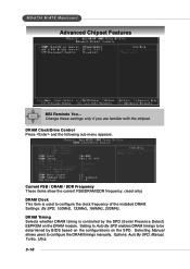
... Control Press and the following sub-menu appears. Setting to Auto By SPD enables DRAM timings to configure the DRAM timings manually. MS-6734 M-ATX Mainboard Advanced Chipset Features MSI Reminds You... Current FSB / DRAM / DDR Frequency These items show the current FSB/DRAM/DDR frequency. (read only) DRAM Clock This item...
... Control Press and the following sub-menu appears. Setting to Auto By SPD enables DRAM timings to configure the DRAM timings manually. MS-6734 M-ATX Mainboard Advanced Chipset Features MSI Reminds You... Current FSB / DRAM / DDR Frequency These items show the current FSB/DRAM/DDR frequency. (read only) DRAM Clock This item...
User Guide
Page 45
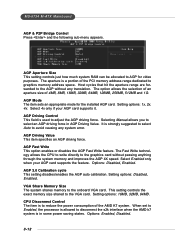
... PCI memory address range dedicated to the onboard VGA card. The aperture is to select an AGP driving force in some power saving states. MS-6734 M-ATX Mainboard AGP & P2P Bridge Control Press and the following sub-menu appears. Selecting Manual allows you to reduce the power consumption of 4MB, 8MB...
... PCI memory address range dedicated to the onboard VGA card. The aperture is to select an AGP driving force in some power saving states. MS-6734 M-ATX Mainboard AGP & P2P Bridge Control Press and the following sub-menu appears. Selecting Manual allows you to reduce the power consumption of 4MB, 8MB...

User Guide
Page 47
... Ultra DMA/33, Ultra DMA/66 and Ultra DMA/100 select Auto to enable/disable the onboard USB1.1 controller. Setting options: Disabled, Enabled. 3-14 MS-6734 M-ATX Mainboard Primary/Secondary Master/Slave PIO The four IDE PIO (Programmed Input/Output) fields let you set the field to auto-detect the LAN...
... Ultra DMA/33, Ultra DMA/66 and Ultra DMA/100 select Auto to enable/disable the onboard USB1.1 controller. Setting options: Disabled, Enabled. 3-14 MS-6734 M-ATX Mainboard Primary/Secondary Master/Slave PIO The four IDE PIO (Programmed Input/Output) fields let you set the field to auto-detect the LAN...