
User Guide
Page 2
... be used in a commercial environment. power cord, if any, must accept any interference received, including interference that may cause undesired operation ii Micro-Star International MS-6734 This device complies with Part 15 of the FCC rules. VOIR LA NOTICE D'INSTALLATION AVANT DE RACCORDER AU RESEAU. Notice 1 The changes or modifications not...
... be used in a commercial environment. power cord, if any, must accept any interference received, including interference that may cause undesired operation ii Micro-Star International MS-6734 This device complies with Part 15 of the FCC rules. VOIR LA NOTICE D'INSTALLATION AVANT DE RACCORDER AU RESEAU. Notice 1 The changes or modifications not...

User Guide
Page 7
The KM4M / KM4AM v1.x Micro-ATX mainboard is based on VIA® Apollo KM400/400A North Bridge & VT8235/8237 South Bridge chipset for purchasing the KM4M / KM4AM (MS-6734 v1.x) MicroATX mainboard. Getting Started Getting Started Thank you for optimal system efficiency. Designed to fit the advanced AMD® Athlon™, Athlon™ XP or Duron™ processors, the KM4M / KM4AM delivers a high performance and professional desktop platform solution. 1-1
The KM4M / KM4AM v1.x Micro-ATX mainboard is based on VIA® Apollo KM400/400A North Bridge & VT8235/8237 South Bridge chipset for purchasing the KM4M / KM4AM (MS-6734 v1.x) MicroATX mainboard. Getting Started Getting Started Thank you for optimal system efficiency. Designed to fit the advanced AMD® Athlon™, Athlon™ XP or Duron™ processors, the KM4M / KM4AM delivers a high performance and professional desktop platform solution. 1-1

User Guide
Page 8
MS-6734 M-ATX Mainboard Mainboard Specifications CPU h Supports Socket A (Socket-462) for AMD® /Athlon™ XP /Sempron™ processors h Supports AMD Athlon XP Sempron 3200+ @ 200 ... h Supports 2 SATA devices (for KM400A only) (For the updated supporting memory modules, please visit http://www.msi.com. Supports DDR200/266/333/400* (*for KM4M) (For the latest information about CPU, please visit http://www.msi.com.tw/program/products/mainboard/mbd/pro_mbd_cpu_support.php) Chipset h VIA® KM400/400A North Bridge - Integrated S-ATA...
MS-6734 M-ATX Mainboard Mainboard Specifications CPU h Supports Socket A (Socket-462) for AMD® /Athlon™ XP /Sempron™ processors h Supports AMD Athlon XP Sempron 3200+ @ 200 ... h Supports 2 SATA devices (for KM400A only) (For the updated supporting memory modules, please visit http://www.msi.com. Supports DDR200/266/333/400* (*for KM4M) (For the latest information about CPU, please visit http://www.msi.com.tw/program/products/mainboard/mbd/pro_mbd_cpu_support.php) Chipset h VIA® KM400/400A North Bridge - Integrated S-ATA...

User Guide
Page 10
ATX Power Supply FDD1 MS-6734 M-ATX Mainboard Mainboard Layout Top : mouse Bottom: keyboard T:1394 port (Optional) B:USB ports SOCKET 462 CPUFA1 Winbond 83697HF BIOS Top : LPT Bottom: COM A VGA port JPW1 T: RJ45 LAN jack B: USB ports T:Line-In M:Line-Out B:Mic VIA VT6103 VIA VT6307 (Optional) J1394_2 (Optional) Codec JAUD1 VIA KM400/400A SYSFA1 AGP Slot PCI Slot 1 BATT + PCI Slot 2 PCI Slot 3 J1394_1 (Optional) JCD1 JSP1 VIA VT8235/8237 SW1 SW2 JUSB2 JUSB3(Optional) JFP1 JFP2 MS-6734 v1.X M-ATX Mainboard DIMM 1 IDE 1 IDE 2 1-4
ATX Power Supply FDD1 MS-6734 M-ATX Mainboard Mainboard Layout Top : mouse Bottom: keyboard T:1394 port (Optional) B:USB ports SOCKET 462 CPUFA1 Winbond 83697HF BIOS Top : LPT Bottom: COM A VGA port JPW1 T: RJ45 LAN jack B: USB ports T:Line-In M:Line-Out B:Mic VIA VT6103 VIA VT6307 (Optional) J1394_2 (Optional) Codec JAUD1 VIA KM400/400A SYSFA1 AGP Slot PCI Slot 1 BATT + PCI Slot 2 PCI Slot 3 J1394_1 (Optional) JCD1 JSP1 VIA VT8235/8237 SW1 SW2 JUSB2 JUSB3(Optional) JFP1 JFP2 MS-6734 v1.X M-ATX Mainboard DIMM 1 IDE 1 IDE 2 1-4

User Guide
Page 14
... away from the socket. As the CPU is likely to move while the lever is correctly installed, the pins should point towards the lever pivot. MS-6734 M-ATX Mainboard CPU Installation Procedures for the gold arrow. The gold arrow should be completely embedded into the socket and close the lever with your...
... away from the socket. As the CPU is likely to move while the lever is correctly installed, the pins should point towards the lever pivot. MS-6734 M-ATX Mainboard CPU Installation Procedures for the gold arrow. The gold arrow should be completely embedded into the socket and close the lever with your...

User Guide
Page 16
BIOS Setup. MSI Reminds You... Replacing the CPU While replacing the CPU, always turn off the ATX power supply or unplug the power supply's power cord from overheating. ... damages or risks caused by default. Overclocking This motherboard is installed on the board, you have to Frequency/Voltage Control in the BIOS setup utility. MS-6734 M-ATX Mainboard CPU Clock Frequency Selection through BIOS The hardware configuration for CPU clock frequency of CPU. However, please make sure the cooling fan can...
BIOS Setup. MSI Reminds You... Replacing the CPU While replacing the CPU, always turn off the ATX power supply or unplug the power supply's power cord from overheating. ... damages or risks caused by default. Overclocking This motherboard is installed on the board, you have to Frequency/Voltage Control in the BIOS setup utility. MS-6734 M-ATX Mainboard CPU Clock Frequency Selection through BIOS The hardware configuration for CPU clock frequency of CPU. However, please make sure the cooling fan can...

User Guide
Page 18
MS-6734 M-ATX Mainboard DIMM Module Combination Install at each side of module. You can barely see the golden finger if the module is deeply inserted in ... S/D (Bank 0 & 1) DIMM 2 DDR S/D (Bank 2 & 3) Maximum System Memory Suppported Total Memory 64MB~1GB 64MB~1GB 64MB~2GB S: Single Side D: Double Side Installing DDR Modules 1. Volt Notch MSI Reminds You... The plastic clip at least one notch on the center of the DIMM slot will only fit in any order to meet your...
MS-6734 M-ATX Mainboard DIMM Module Combination Install at each side of module. You can barely see the golden finger if the module is deeply inserted in ... S/D (Bank 0 & 1) DIMM 2 DDR S/D (Bank 2 & 3) Maximum System Memory Suppported Total Memory 64MB~1GB 64MB~1GB 64MB~2GB S: Single Side D: Double Side Installing DDR Modules 1. Volt Notch MSI Reminds You... The plastic clip at least one notch on the center of the DIMM slot will only fit in any order to meet your...

User Guide
Page 20
You can plug a PS/2® mouse directly into this connector. MS-6734 M-ATX Mainboard Back Panel The back panel provides the following connectors: Mouse IEEE1394 (Optional) Parallel LAN (Optional) Keyboard USB COM VGA USB L-in L-out MIC ...
You can plug a PS/2® mouse directly into this connector. MS-6734 M-ATX Mainboard Back Panel The back panel provides the following connectors: Mouse IEEE1394 (Optional) Parallel LAN (Optional) Keyboard USB COM VGA USB L-in L-out MIC ...

User Guide
Page 22
MS-6734 M-ATX Mainboard Serial Port Connector: COM 1 The mainboard offers one standard IEEE 1394 port. The IEEE1394 high-speed serial bus complements USB by providing enhanced ...
MS-6734 M-ATX Mainboard Serial Port Connector: COM 1 The mainboard offers one standard IEEE 1394 port. The IEEE1394 high-speed serial bus complements USB by providing enhanced ...

User Guide
Page 26
... hard disk drives, CD-ROM, 120MB Floppy (reserved for jumper setting instructions. 2-16 IDE1 can also connect a Master and a Slave drive. MSI Reminds You... You can connect up to the hard disk documentation supplied by hard disk vendors for future BIOS) and other devices. If you install... two hard disks on cable, you must configure second hard drive to Slave mode by setting the jumper accordingly. MS-6734 M-ATX Mainboard Hard Disk Connectors: IDE1 & IDE2 The mainboard has a 32-bit Enhanced PCI IDE and Ultra DMA 33/66/100/133 controller...
... hard disk drives, CD-ROM, 120MB Floppy (reserved for jumper setting instructions. 2-16 IDE1 can also connect a Master and a Slave drive. MSI Reminds You... You can connect up to the hard disk documentation supplied by hard disk vendors for future BIOS) and other devices. If you install... two hard disks on cable, you must configure second hard drive to Slave mode by setting the jumper accordingly. MS-6734 M-ATX Mainboard Hard Disk Connectors: IDE1 & IDE2 The mainboard has a 32-bit Enhanced PCI IDE and Ultra DMA 33/66/100/133 controller...

User Guide
Page 28
MS-6734 M-ATX Mainboard Front Panel Connectors: JFP1 & JFP2 The mainboard provides two front panel connectors for CD-ROM audio connector. 2-18 R L GND JCD1 Do not use. ...
MS-6734 M-ATX Mainboard Front Panel Connectors: JFP1 & JFP2 The mainboard provides two front panel connectors for CD-ROM audio connector. 2-18 R L GND JCD1 Do not use. ...

User Guide
Page 30
MS-6734 M-ATX Mainboard IEEE 1394 Connectors: J1394_1 & J1394_2 (Optional) The mainboard provides one or two optional 1394 pin headers J1394_1 and J1394_2 that allow you to connect optional IEEE 1394 ports. 9 1 10 2 J1394_1 / J1394_2 (Optional) Pin Definition PIN SIGNAL PIN 1 TPA+ 2 3 Ground 4 5 TPB+ 6 7 Cable power 8 9 Key (no pin) 10 SIGNAL TPAGround TPBCable power Ground IEEE1394 Bracket (Optional) Foolproof Design 2-20
MS-6734 M-ATX Mainboard IEEE 1394 Connectors: J1394_1 & J1394_2 (Optional) The mainboard provides one or two optional 1394 pin headers J1394_1 and J1394_2 that allow you to connect optional IEEE 1394 ports. 9 1 10 2 J1394_1 / J1394_2 (Optional) Pin Definition PIN SIGNAL PIN 1 TPA+ 2 3 Ground 4 5 TPB+ 6 7 Cable power 8 9 Key (no pin) 10 SIGNAL TPAGround TPBCable power Ground IEEE1394 Bracket (Optional) Foolproof Design 2-20

User Guide
Page 32
.... You can automatically boot OS every time it will explain how to change your motherboard's function through the use of system configuration. MS-6734 M-ATX Mainboard Jumpers The motherboard provides the following jumpers for you want to clear the system configuration, se the JBAT1 (Clear CMOS ... only) 3 1 SW1 2-22 3 1 SW2 3 1 SW2 3 1 SW2 3 1 SW2 Then return to clear the data: 3 1 3 1 3 1 JBAT1 Clear Data Keep Data MSI Reminds You... it is off. Clear CMOS Jumper: JBAT1 There is on; With the CMOS RAM, the system can clear CMOS by shorting 2-3 pin while...
.... You can automatically boot OS every time it will explain how to change your motherboard's function through the use of system configuration. MS-6734 M-ATX Mainboard Jumpers The motherboard provides the following jumpers for you want to clear the system configuration, se the JBAT1 (Clear CMOS ... only) 3 1 SW1 2-22 3 1 SW2 3 1 SW2 3 1 SW2 3 1 SW2 Then return to clear the data: 3 1 3 1 3 1 JBAT1 Clear Data Keep Data MSI Reminds You... it is off. Clear CMOS Jumper: JBAT1 There is on; With the CMOS RAM, the system can clear CMOS by shorting 2-3 pin while...

User Guide
Page 35
... find a right pointer symbol (as shown in the right view) appears to the left hand Move to the item in the left of the screen. MS-6734 M-ATX Mainboard Entering Setup Power on the screen, press key to . When the message below appears on the computer and the system will see is...
... find a right pointer symbol (as shown in the right view) appears to the left hand Move to the item in the left of the screen. MS-6734 M-ATX Mainboard Entering Setup Power on the screen, press key to . When the message below appears on the computer and the system will see is...

User Guide
Page 37
... exit setup. Save & Exit Setup Save changes to set User Password. Load Optimized Defaults Use this menu to specify your settings for frequency/voltage control. MS-6734 M-ATX Mainboard Frequency/Voltage Control Use this menu to load factory default settings into the BIOS for stable system performance operations.
... exit setup. Save & Exit Setup Save changes to set User Password. Load Optimized Defaults Use this menu to specify your settings for frequency/voltage control. MS-6734 M-ATX Mainboard Frequency/Voltage Control Use this menu to load factory default settings into the BIOS for stable system performance operations.
User Guide
Page 39
... only). 3-6 Available options: None, 360K 5.25, 1.2 MB 5.25, 720 KB 3.5, 1.44 MB 3.5 and 2.88 MB 3.5. The system doesn't stop for the primary monitor of cylinders. MS-6734 M-ATX Mainboard If you to set the type of floppy drives installed. Base/Extended/Total Memory The three items show the memory status of your...
... only). 3-6 Available options: None, 360K 5.25, 1.2 MB 5.25, 720 KB 3.5, 1.44 MB 3.5 and 2.88 MB 3.5. The system doesn't stop for the primary monitor of cylinders. MS-6734 M-ATX Mainboard If you to set the type of floppy drives installed. Base/Extended/Total Memory The three items show the memory status of your...

User Guide
Page 41
... and when the acceleration begins. Settings are described below: Option Description Setup System The password prompt appears only when end users try to run Setup. MS-6734 M-ATX Mainboard CPU Internal Cache The item allows you to turn on the Num Lock key when the system is powered on. Setting to use...
... and when the acceleration begins. Settings are described below: Option Description Setup System The password prompt appears only when end users try to run Setup. MS-6734 M-ATX Mainboard CPU Internal Cache The item allows you to turn on the Num Lock key when the system is powered on. Setting to use...
User Guide
Page 43
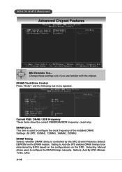
... of the installed DRAM. Settings: By SPD, 100MHz, 133MHz, 166MHz, 200MHz. DRAM Timing Selects whether DRAM timing is used to configure the DRAM timings manually. MS-6734 M-ATX Mainboard Advanced Chipset Features MSI Reminds You...
... of the installed DRAM. Settings: By SPD, 100MHz, 133MHz, 166MHz, 200MHz. DRAM Timing Selects whether DRAM timing is used to configure the DRAM timings manually. MS-6734 M-ATX Mainboard Advanced Chipset Features MSI Reminds You...
User Guide
Page 45
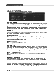
Setting options: 1x, 2x, 4x. Selecting Manual allows you to reduce the power consumption of the AMD K7 system. Setting options: Disabled, Enabled. MS-6734 M-ATX Mainboard AGP & P2P Bridge Control Press and the following sub-menu appears. CPU Disconnect Control The item is to select an AGP driving force ...
Setting options: 1x, 2x, 4x. Selecting Manual allows you to reduce the power consumption of the AMD K7 system. Setting options: Disabled, Enabled. MS-6734 M-ATX Mainboard AGP & P2P Bridge Control Press and the following sub-menu appears. CPU Disconnect Control The item is to select an AGP driving force ...

User Guide
Page 47
... to enable/disable the onboard USB1.1 controller. Setting options: Disabled, Enabled. 3-14 The settings are : Auto, Mode 0, Mode 1, Mode 2, Mode 3, Mode 4. Setting options: Disabled, Enabled. MS-6734 M-ATX Mainboard Primary/Secondary Master/Slave PIO The four IDE PIO (Programmed Input/Output) fields let you set the field to auto-detect the LAN...
... to enable/disable the onboard USB1.1 controller. Setting options: Disabled, Enabled. 3-14 The settings are : Auto, Mode 0, Mode 1, Mode 2, Mode 3, Mode 4. Setting options: Disabled, Enabled. MS-6734 M-ATX Mainboard Primary/Secondary Master/Slave PIO The four IDE PIO (Programmed Input/Output) fields let you set the field to auto-detect the LAN...

