User Guide
Page 2
... guide, BIOS updates, driver updates, and other countries. We take every care in the preparation of this document is the intellectual property of its contents. Award® is a registered trademark of Novell, Inc. Visit the MSI website for PCB 1.X Date March 2008 Technical Support If a problem arises with your system and no guarantee is a registered trademark of Phoenix Technologies Ltd...
... guide, BIOS updates, driver updates, and other countries. We take every care in the preparation of this document is the intellectual property of its contents. Award® is a registered trademark of Novell, Inc. Visit the MSI website for PCB 1.X Date March 2008 Technical Support If a problem arises with your system and no guarantee is a registered trademark of Phoenix Technologies Ltd...
User Guide
Page 8
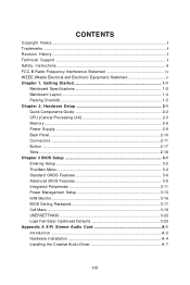
...Power Supply ...2-8 Back Panel ...2-10 Connectors ...2-11 Button ...2-17 Slots ...2-18 Chapter 3 BIOS Setup 3-1 Entering Setup ...3-2 The Main Menu ...3-4 Standard CMOS Features 3-6 Advanced BIOS Features 3-8 Integrated Peripherals 3-11 Power Management Setup 3-13 H/W Monitor ...3-16 BIOS Setting Password 3-17 Cell Menu ...3-18 USERSETTINGS 3-22 Load Fail-Safe/ Optimized Defaults 3-23 Appendix A X-Fi Xtreme Audio Card A-1 Introduction ...A-2 Hardware Installation A-4 Installing the Creative Audio Driver A-7 viii Getting Started 1-1 Mainboard Specifications 1-2 Mainboard Layout...
...Power Supply ...2-8 Back Panel ...2-10 Connectors ...2-11 Button ...2-17 Slots ...2-18 Chapter 3 BIOS Setup 3-1 Entering Setup ...3-2 The Main Menu ...3-4 Standard CMOS Features 3-6 Advanced BIOS Features 3-8 Integrated Peripherals 3-11 Power Management Setup 3-13 H/W Monitor ...3-16 BIOS Setting Password 3-17 Cell Menu ...3-18 USERSETTINGS 3-22 Load Fail-Safe/ Optimized Defaults 3-23 Appendix A X-Fi Xtreme Audio Card A-1 Introduction ...A-2 Hardware Installation A-4 Installing the Creative Audio Driver A-7 viii Getting Started 1-1 Mainboard Specifications 1-2 Mainboard Layout...
User Guide
Page 11
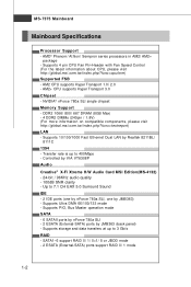
... storage and data transfers at up to 7.1 CH EAX 5.0 Surround Sound IDE - 2 IDE ports (one by nForce 780a SLI, one by Realtek 8211BL/ 8111C 1394 - AM2+ CPU supports Hyper Transport 3.0 Chipset - Controlled by JMB363 (back panel) - SATA1~6 support RAID 0/ 1/ 0+1/ 5 or JBOD mode - 2 ESATA (External-SATA) ports support RAID 0/ 1 mode 1-2 AMD® Phenom/ Athlon/ Sempron series processors in AM2/ AM2+ package - ms i. t w / i ndex . NVIDIA® nForce 780a SLI single chipset Memory Support - c om. Supports Ultra DMA 66/100/133 mode - MS-7375 Mainboard Mainboard Specifications...
... storage and data transfers at up to 7.1 CH EAX 5.0 Surround Sound IDE - 2 IDE ports (one by nForce 780a SLI, one by Realtek 8211BL/ 8111C 1394 - AM2+ CPU supports Hyper Transport 3.0 Chipset - Controlled by JMB363 (back panel) - SATA1~6 support RAID 0/ 1/ 0+1/ 5 or JBOD mode - 2 ESATA (External-SATA) ports support RAID 0/ 1 mode 1-2 AMD® Phenom/ Athlon/ Sempron series processors in AM2/ AM2+ package - ms i. t w / i ndex . NVIDIA® nForce 780a SLI single chipset Memory Support - c om. Supports Ultra DMA 66/100/133 mode - MS-7375 Mainboard Mainboard Specifications...

User Guide
Page 12
... with PCIE 2.0 specification a. ATX (30.5cm X 24.4 cm) Mounting - 9 mounting holes 1-3 support 3-W ay SLI, these three PCIE x16 lanes will configure to x16/ x16/ x0 . - 1 PCI Express x 1 slot - 2 PCI slots Form Factor - Getting Started Floppy - 1 floppy port - Supports TPM Slots - 3 PCI Express x16 slots compatible with 360KB, 720KB, 1.2MB, 1.44MB and 2.88MB Connectors Back panel - 1 PS/2 mouse port - 1 PS/2 keyboard port - 1 1394 port - 1 DVI-D port - 2 LAN jacks - 4 USB 2.0 ports - 2 ESATA ports On-Board Pinheaders - 3 USB 2.0 pinheaders - 1 1394 pinheader - 1 Serial port pinheader...
... with PCIE 2.0 specification a. ATX (30.5cm X 24.4 cm) Mounting - 9 mounting holes 1-3 support 3-W ay SLI, these three PCIE x16 lanes will configure to x16/ x16/ x0 . - 1 PCI Express x 1 slot - 2 PCI slots Form Factor - Getting Started Floppy - 1 floppy port - Supports TPM Slots - 3 PCI Express x16 slots compatible with 360KB, 720KB, 1.2MB, 1.44MB and 2.88MB Connectors Back panel - 1 PS/2 mouse port - 1 PS/2 keyboard port - 1 1394 port - 1 DVI-D port - 2 LAN jacks - 4 USB 2.0 ports - 2 ESATA ports On-Board Pinheaders - 3 USB 2.0 pinheaders - 1 1394 pinheader - 1 Serial port pinheader...
User Guide
Page 17
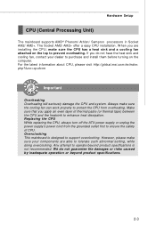
... ATX power supply or unplug the power supply's power cord from overheating. Any attempt to prevent overheating. We do not have the heat sink and cooling fan, contact your components are installing the CPU, make sure your dealer to purchase and install them before turning on the top to operate beyond product specifications. 2-3 Hardware Setup CPU (Central Processing Unit) The mainboard supports AMD® Phenom/ Athlon/ Sempron processors in Socket...
... ATX power supply or unplug the power supply's power cord from overheating. Any attempt to prevent overheating. We do not have the heat sink and cooling fan, contact your components are installing the CPU, make sure your dealer to purchase and install them before turning on the top to operate beyond product specifications. 2-3 Hardware Setup CPU (Central Processing Unit) The mainboard supports AMD® Phenom/ Athlon/ Sempron processors in Socket...

User Guide
Page 24
... Network (LAN). On (steady state) LAN link is for a PS/2® mouse/keyboard. On 1000 Mbit/sec data rate is for more information.) 1394 Port The IEEE1394 port on the LAN. LAN The standard RJ-45 LAN jack is selected. To connect an LCD monitor, simply plug your monitor cable into the DVI connector, and make sure that the other USB-compatible devices. You can also use the optional external SATA cable...
... Network (LAN). On (steady state) LAN link is for a PS/2® mouse/keyboard. On 1000 Mbit/sec data rate is for more information.) 1394 Port The IEEE1394 port on the LAN. LAN The standard RJ-45 LAN jack is selected. To connect an LCD monitor, simply plug your monitor cable into the DVI connector, and make sure that the other USB-compatible devices. You can also use the optional external SATA cable...

User Guide
Page 25
... and a Slave drive. Important If you install two IDE devices on the same cable, you must configure the drives separately to IDE device's documentation supplied by setting jumpers. IDE2 (Secondary IDE Connector) IDE2 can connect a Master and a Slave drive. Refer to master / slave mode by the vendors for jumper setting instructions. 2-11 IDE1 IDE2 IDE1 (Primary IDE Connector) The first hard drive should always be connected to IDE1. Hardware Setup Connectors IDE Connector: IDE1 / IDE2 This connector supports IDE hard disk drives, optical disk drives and other IDE devices.
... and a Slave drive. Important If you install two IDE devices on the same cable, you must configure the drives separately to IDE device's documentation supplied by setting jumpers. IDE2 (Secondary IDE Connector) IDE2 can connect a Master and a Slave drive. Refer to master / slave mode by the vendors for jumper setting instructions. 2-11 IDE1 IDE2 IDE1 (Primary IDE Connector) The first hard drive should always be connected to IDE1. Hardware Setup Connectors IDE Connector: IDE1 / IDE2 This connector supports IDE hard disk drives, optical disk drives and other IDE devices.

User Guide
Page 27
... CPU cooling fan. 2. Serial Port Connector: JCOM1 This connector is Ground and should be connected to the actual CPU temperature. 3. the black wire is a 16550A high speed communication port that will automatically control the CPU fan speed according to GND. You can install Dual Core Center utility that sends/receives 16 bytes FIFOs. If the mainboard has a System Hardware Monitor chipset on-board, you must use a specially designed fan with +12V. CPUFAN supports fan control. You can attach a serial device. Pin Definition 2 1 9 JCOM1 PIN...
... CPU cooling fan. 2. Serial Port Connector: JCOM1 This connector is Ground and should be connected to the actual CPU temperature. 3. the black wire is a 16550A high speed communication port that will automatically control the CPU fan speed according to GND. You can install Dual Core Center utility that sends/receives 16 bytes FIFOs. If the mainboard has a System Hardware Monitor chipset on-board, you must use a specially designed fan with +12V. CPUFAN supports fan control. You can attach a serial device. Pin Definition 2 1 9 JCOM1 PIN...

User Guide
Page 32
MS-7375 Mainboard Slots PCI (Peripheral Component Interconnect) Express Slots The PCI Express slot supports the PCI Express interface expansion card. support 3-Way SLI, these three PCIE x16 lanes will configure to run full x16 speed. 2. b. c. The PCI Express 2.0 x 8 supports up to x16/ x8/ x8. The PCI Express 2.0 x 16 supports up to 8.0 GB/s transfer rate. When adding or removing expansion cards, make sure that you intend to install only ONE x16 graphics card, please install this graphics card in mazarine PCIE x16 (PCI_E2...
MS-7375 Mainboard Slots PCI (Peripheral Component Interconnect) Express Slots The PCI Express slot supports the PCI Express interface expansion card. support 3-Way SLI, these three PCIE x16 lanes will configure to run full x16 speed. 2. b. c. The PCI Express 2.0 x 8 supports up to x16/ x8/ x8. The PCI Express 2.0 x 16 supports up to 8.0 GB/s transfer rate. When adding or removing expansion cards, make sure that you intend to install only ONE x16 graphics card, please install this graphics card in mazarine PCIE x16 (PCI_E2...

User Guide
Page 37
... SLI technology, delivers multi-GPU benefits when an NVIDIA mainboard GPU is combined with the graphic card and boost the performance of mainboard) will share the rendering load with an NVIDIA discrete GPU. The chipset will work. Hence, you have installed the graphics card in the System tray can select the Hybird mode. Hybrid-Performance M ode - Click on the Hybrid Icon in the PCI Express slot, only the onboard video...
... SLI technology, delivers multi-GPU benefits when an NVIDIA mainboard GPU is combined with the graphic card and boost the performance of mainboard) will share the rendering load with an NVIDIA discrete GPU. The chipset will work. Hence, you have installed the graphics card in the System tray can select the Hybird mode. Hybrid-Performance M ode - Click on the Hybrid Icon in the PCI Express slot, only the onboard video...

User Guide
Page 38
...) Slots The PCI slots support LAN cards, SCSI cards, USB cards, and other add-on cards that you unplug the power supply first. At 32 bits and 33 MHz, it yields a throughput rate of 133 MBps. 32-bit PCI Slot PCI Interrupt Request Routing The IRQ, acronym of interrupt request line and pronounced I-R-Q, are typically connected to configure any necessary hardware or software settings for the expansion card to the PCI bus pins as jumpers, switches or BIOS configuration...
...) Slots The PCI slots support LAN cards, SCSI cards, USB cards, and other add-on cards that you unplug the power supply first. At 32 bits and 33 MHz, it yields a throughput rate of 133 MBps. 32-bit PCI Slot PCI Interrupt Request Routing The IRQ, acronym of interrupt request line and pronounced I-R-Q, are typically connected to configure any necessary hardware or software settings for the expansion card to the PCI bus pins as jumpers, switches or BIOS configuration...

User Guide
Page 45
... HD devices to the IDE/ SATA/ E-SATA connector on the mainboard. This allows you to activate the S.M.A.R.T. (Self-Monitoring Analysis & Reporting Technology) capability for the hard disks. Floppy Drive A This item allows you to set the type of your disk status to move data from a hard disk that monitors your system (read only). 3-7 This gives you an opportunity to predict hard disk failure. This sub-menu shows the CPU information, BIOS version and memory status of floppy drives installed...
... HD devices to the IDE/ SATA/ E-SATA connector on the mainboard. This allows you to activate the S.M.A.R.T. (Self-Monitoring Analysis & Reporting Technology) capability for the hard disks. Floppy Drive A This item allows you to set the type of your disk status to move data from a hard disk that monitors your system (read only). 3-7 This gives you an opportunity to predict hard disk failure. This sub-menu shows the CPU information, BIOS version and memory status of floppy drives installed...

User Guide
Page 47
.... Hybrid SLI support This item is part of the chipset. This setting controls the exact memory size shared to the on -chip VGA. VGA Share Memory Size The system shares memory to the on-chip VGA. You can to enable it, and will provide you should set to higher values, every PCI device can hold the bus before another takes over. BIOS Setup Primary Graphic's Adapter This setting specifies which graphic card is used to enable or disable the on -chip VGA. 3-9
.... Hybrid SLI support This item is part of the chipset. This setting controls the exact memory size shared to the on -chip VGA. VGA Share Memory Size The system shares memory to the on-chip VGA. You can to enable it, and will provide you should set to higher values, every PCI device can hold the bus before another takes over. BIOS Setup Primary Graphic's Adapter This setting specifies which graphic card is used to enable or disable the on -chip VGA. 3-9

User Guide
Page 54
... of the monitored hardware devices/ components such as CPU voltage, temperatures and all fans' speeds. 3-16 CPU/ System Temperature, CPU FAN/ SYS FAN1/ SYS FAN2 Speed, CPU Vcore, 3.3V, 5V, 12V These items display the current status of all of SYSFAN1 speed. ---- To clear the warning message, set a FAN target in . CPU Smart FAN Target The mainboard provides the Smart Fan function which can select a fan target value here. SYS FAN1 Control This item is used to...
... of the monitored hardware devices/ components such as CPU voltage, temperatures and all fans' speeds. 3-16 CPU/ System Temperature, CPU FAN/ SYS FAN1/ SYS FAN2 Speed, CPU Vcore, 3.3V, 5V, 12V These items display the current status of all of SYSFAN1 speed. ---- To clear the warning message, set a FAN target in . CPU Smart FAN Target The mainboard provides the Smart Fan function which can select a fan target value here. SYS FAN1 Control This item is used to...
User Guide
Page 59
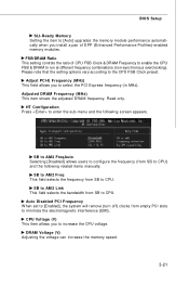
... to CPU. CPU Voltage (V) This item allows you to select the PCI Express frequency (in MHz). Adjusted DRAM Frequency (M Hz) This item shows the adjusted DRAM frequency. DRAM Voltage (V) Adjusting the voltage can increase the memory speed. 3-21 BIOS Setup SLI-Ready Memory Setting the item to [Auto] upgrades the memory module performance automatically when you install a pair of CPU FSB Clock & DRAM Frequency to enable the CPU FSB & DRAM to run at different frequency combinations (non-synchronous overclocking). FSB/DRAM Ratio This setting controls the...
... to CPU. CPU Voltage (V) This item allows you to select the PCI Express frequency (in MHz). Adjusted DRAM Frequency (M Hz) This item shows the adjusted DRAM frequency. DRAM Voltage (V) Adjusting the voltage can increase the memory speed. 3-21 BIOS Setup SLI-Ready Memory Setting the item to [Auto] upgrades the memory module performance automatically when you install a pair of CPU FSB Clock & DRAM Frequency to enable the CPU FSB & DRAM to run at different frequency combinations (non-synchronous overclocking). FSB/DRAM Ratio This setting controls the...
User Guide
Page 71
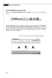
In each Task, please refer to get the online help information A-10 For more information and usage details on the "?" Launcher Click on this button to its configuraton screen. Launcher icon to get the online help information). Launcher consists of various tabs such as Programs, Product Settings, Product Support and Companion Products. click on the Creative MediaSource Go! button to enter its online Help (simply click on each tab, you can access different applications, called Tasks. Creatvie MediaSource Go! MS-7375 Mainboard Creative MediaSource Go!
In each Task, please refer to get the online help information A-10 For more information and usage details on the "?" Launcher Click on this button to its configuraton screen. Launcher icon to get the online help information). Launcher consists of various tabs such as Programs, Product Settings, Product Support and Companion Products. click on the Creative MediaSource Go! button to enter its online Help (simply click on each tab, you can access different applications, called Tasks. Creatvie MediaSource Go! MS-7375 Mainboard Creative MediaSource Go!

User Guide
Page 80
... RAID function in the system BIOS. (Refer the bios section for details.) 4. Choose the hard disks that are to Optimal. Boot from the W indows CD, use the floppy disk that press F10 to copy and install the nForce RAID software. (Check p.B-7 for details.) 2. NVRAID BIOS setup lets you choose the RAID array type and which hard drives you to be RAID enabled in BIOS before configuring the NVRAID BIOS. Press F10, and the NVIDIA RAID Utility --- nVidia RAID RAID Configuration Basic Configuration Instructions...
... RAID function in the system BIOS. (Refer the bios section for details.) 4. Choose the hard disks that are to Optimal. Boot from the W indows CD, use the floppy disk that press F10 to copy and install the nForce RAID software. (Check p.B-7 for details.) 2. NVRAID BIOS setup lets you choose the RAID array type and which hard drives you to be RAID enabled in BIOS before configuring the NVRAID BIOS. Press F10, and the NVIDIA RAID Utility --- nVidia RAID RAID Configuration Basic Configuration Instructions...

User Guide
Page 84
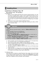
... USB). Click the "Browse CD" on the "Load Driver" button to select "Specify Additional Device". 3. You should be shown a list of W indows XP installation is the case, then you are already in the \\nVidia\System\MCP72\IDE\WinXP\Sataraid\Floppy to a formatted floppy disk. \\chipset\nVidia\Vista32\MCP72\IDE\WinVista\Sataraid to complete the whole installation. You should be prompted to make an "NVIDIA RAID Driver" for NVIDIA RAID Controller is done. 4. Select "NVIDIA NForce Storage Controller...
... USB). Click the "Browse CD" on the "Load Driver" button to select "Specify Additional Device". 3. You should be shown a list of W indows XP installation is the case, then you are already in the \\nVidia\System\MCP72\IDE\WinXP\Sataraid\Floppy to a formatted floppy disk. \\chipset\nVidia\Vista32\MCP72\IDE\WinVista\Sataraid to complete the whole installation. You should be prompted to make an "NVIDIA RAID Driver" for NVIDIA RAID Controller is done. 4. Select "NVIDIA NForce Storage Controller...
User Guide
Page 104
... the "Load Driver" button to insert a floppy disk containing the JMicron RAID driver into the CD-ROM drive. 2. W indows setup will need to make an "JMicron RAID Driver" for JM icron RAID Controller is the case, then you created in the for XP: \\nvidia\IDE\JMicron\JMB363\Floppy32 (for 32-bit OS) or Floppy64 (for 64bit OS) to a formatted floppy disk. And then, follow the instruction below to supply the driver. If this...
... the "Load Driver" button to insert a floppy disk containing the JMicron RAID driver into the CD-ROM drive. 2. W indows setup will need to make an "JMicron RAID Driver" for JM icron RAID Controller is the case, then you created in the for XP: \\nvidia\IDE\JMicron\JMB363\Floppy32 (for 32-bit OS) or Floppy64 (for 64bit OS) to a formatted floppy disk. And then, follow the instruction below to supply the driver. If this...

User Guide
Page 114
... VGA button to execute the function. Introduction: Click each button appearing above to enter sub-menu to make further configuration or to read current GPU temperature, GPU clock and memory clock of the MSI mainboard would be available. If you : only when installing the MSI V044 (V044 has to enable or disable the Dynamic Overclocking Technology. DOT Click DOT button to install with the version 8.26 or newer driver)/ V046 or V060 graphics card...
... VGA button to execute the function. Introduction: Click each button appearing above to enter sub-menu to make further configuration or to read current GPU temperature, GPU clock and memory clock of the MSI mainboard would be available. If you : only when installing the MSI V044 (V044 has to enable or disable the Dynamic Overclocking Technology. DOT Click DOT button to install with the version 8.26 or newer driver)/ V046 or V060 graphics card...


