User Guide
Page 8
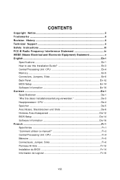
... ...ii Revision History ...ii Technical Support ...ii Safety Instructions iii FCC-B Radio Frequency Interference Statement iv WEEE (Waste Electrical and Electronic Equipment) Statement v English ...En-1 Specifications ...En-1 How to use this Installation Guide En-3 Central Processing Unit: CPU En-4 Memory ...En-5 Connectors, Jumpers, Slots En-6 Back Panel ...En-12 BIOS Setup...
... ...ii Revision History ...ii Technical Support ...ii Safety Instructions iii FCC-B Radio Frequency Interference Statement iv WEEE (Waste Electrical and Electronic Equipment) Statement v English ...En-1 Specifications ...En-1 How to use this Installation Guide En-3 Central Processing Unit: CPU En-4 Memory ...En-5 Connectors, Jumpers, Slots En-6 Back Panel ...En-12 BIOS Setup...
User Guide
Page 9
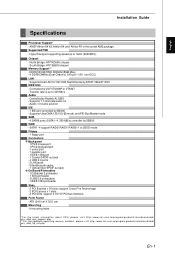
... 400 Mb/s Audio - Supports Ultra DMA 133/100/ 66 mode, and PIO Bus Master mode SATA - 4 SATAII ports (SATA1~4, 300 MB/s) controller by SB600 RAID - ATX (24.5 cm X 30.5 cm) Mounting - 9 mounting holes *For the latest information about CPU, please visit http:// www.ms i.com. English Installation Guide...
... 400 Mb/s Audio - Supports Ultra DMA 133/100/ 66 mode, and PIO Bus Master mode SATA - 4 SATAII ports (SATA1~4, 300 MB/s) controller by SB600 RAID - ATX (24.5 cm X 30.5 cm) Mounting - 9 mounting holes *For the latest information about CPU, please visit http:// www.ms i.com. English Installation Guide...
User Guide
Page 11
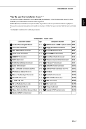
Read the specifications of the mainboard on page En-1. - Components Index Table Component Number page Component Number page 1 Central Processing Unit Socket En-4 3 DDRII Sockets : DIMM1~4 (dual channel) ...-8 16 IrDA Infrared Module Connector En-8 19 D-BracketTM 2 Connector En-9 20 Clear CMOS Jumper En-10 21 ATX 24-Pin Power Connector En-10 23 ATX 12V Power Connector (2x2-Pin) En-10 25 ATX 12V Power Connector (1x4-Pin) En-10 26 PCI Express Slots (x16/ x4/ x1) En-11 27 PCI...
Read the specifications of the mainboard on page En-1. - Components Index Table Component Number page Component Number page 1 Central Processing Unit Socket En-4 3 DDRII Sockets : DIMM1~4 (dual channel) ...-8 16 IrDA Infrared Module Connector En-8 19 D-BracketTM 2 Connector En-9 20 Clear CMOS Jumper En-10 21 ATX 24-Pin Power Connector En-10 23 ATX 12V Power Connector (2x2-Pin) En-10 25 ATX 12V Power Connector (1x4-Pin) En-10 26 PCI Express Slots (x16/ x4/ x1) En-11 27 PCI...
User Guide
Page 13
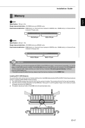
... : All DIMM slots are GREEN color. Dual channels definition : DIMM slot(s) on Channel B are marked in Purple color. 40x2=80 pin 52x2=104 pin 3 DDRII Specification : 240-pin, 1.8v. The plastic clip at each side of the same type and density in GREEN color. English Installation Guide Memory 2 DDR...
... : All DIMM slots are GREEN color. Dual channels definition : DIMM slot(s) on Channel B are marked in Purple color. 40x2=80 pin 52x2=104 pin 3 DDRII Specification : 240-pin, 1.8v. The plastic clip at each side of the same type and density in GREEN color. English Installation Guide Memory 2 DDR...
User Guide
Page 19
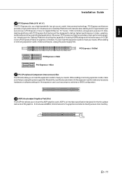
... graphics card. When adding or removing expansion cards, make sure that you to insert the expansion cards to meet your needs. AGP is an interface specification designed for the expansion card, such as a high-bandwidth, low pin count, serial, interconnect technology. Meanwhile, readthe documentation forthe expansion cardto makeany necessary hardware or...
... graphics card. When adding or removing expansion cards, make sure that you to insert the expansion cards to meet your needs. AGP is an interface specification designed for the expansion card, such as a high-bandwidth, low pin count, serial, interconnect technology. Meanwhile, readthe documentation forthe expansion cardto makeany necessary hardware or...
User Guide
Page 23
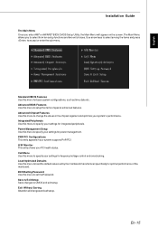
... the values in the chipset registers and optimize your settings for power management. Advanced Chipset Features Use this menu to set by the mainboard manufacturer specifically for fequency/voltage control and overclocking. The Main Menu allows you enter AMI® or AWARD® BIOS CMOS Setup Utility, the Main Menu will...
... the values in the chipset registers and optimize your settings for power management. Advanced Chipset Features Use this menu to set by the mainboard manufacturer specifically for fequency/voltage control and overclocking. The Main Menu allows you enter AMI® or AWARD® BIOS CMOS Setup Utility, the Main Menu will...