User Guide
Page 8
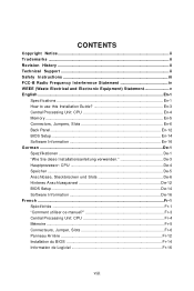
...ii Revision History ...ii Technical Support ...ii Safety Instructions iii FCC-B Radio Frequency Interference Statement iv WEEE (Waste Electrical and Electronic Equipment) Statement v English ...En-1 Specifications ...En-1 How to use this Installation Guide En-3 Central Processing Unit: CPU En-4 Memory ...En-5 Connectors...En-14 Software Information En-16 G e rm an ...De-1 Spezifikationen De-1 "W ie Sie diese Installationsanleitung verwenden De-3 Hauptprozessor: CPU De-4 Speicher ...De-5 Anschlüsse, Steckbrücken und Slots De-6 Hinteres Anschlusspaneel De-12 BIOS Setup ...De-14...
...ii Revision History ...ii Technical Support ...ii Safety Instructions iii FCC-B Radio Frequency Interference Statement iv WEEE (Waste Electrical and Electronic Equipment) Statement v English ...En-1 Specifications ...En-1 How to use this Installation Guide En-3 Central Processing Unit: CPU En-4 Memory ...En-5 Connectors...En-14 Software Information En-16 G e rm an ...De-1 Spezifikationen De-1 "W ie Sie diese Installationsanleitung verwenden De-3 Hauptprozessor: CPU De-4 Speicher ...De-5 Anschlüsse, Steckbrücken und Slots De-6 Hinteres Anschlusspaneel De-12 BIOS Setup ...De-14...
User Guide
Page 9
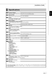
...s, pleas e vi sit htt p:/ /www. Supported FSB - Supports 7.1 channels audio out - ms i. Supports Dual LAN 10/100/1000 Fast Ethernet by Realtek ALC883 - ATX (24.5 cm X 30.5 cm) Mounting - 9 mounting holes *For the latest information about CPU, please visit http:// www.ms i.com. Controlled... by RTL8111B & 8110SC IEEE 1394 - SATA1~4 support RAID0/ RAID1/ RAID0+1 or JBOD mode Floppy - 1 ...
...s, pleas e vi sit htt p:/ /www. Supported FSB - Supports 7.1 channels audio out - ms i. Supports Dual LAN 10/100/1000 Fast Ethernet by Realtek ALC883 - ATX (24.5 cm X 30.5 cm) Mounting - 9 mounting holes *For the latest information about CPU, please visit http:// www.ms i.com. Controlled... by RTL8111B & 8110SC IEEE 1394 - SATA1~4 support RAID0/ RAID1/ RAID0+1 or JBOD mode Floppy - 1 ...
User Guide
Page 12
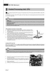
...correct installation Gold arrow procedures may vary depending on the computer. MS-7280 Mainboard Central Processing Unit: CPU 1 The mainboard supports VIA® processor. The mainboard uses a CPU socket called Socket AM2 for Socket AM2 1. Please turn off the power and unplug the power ... close the lever. For the latest information about CPU, please visit http://www.msi.com.tw/program/products/mainboard/mbd/ pro_mbd_cpu_support.php Important Overheating Overheating will seriously damage the CPU and system, always make sure the CPU is correctly installed, the pins should point as ...
...correct installation Gold arrow procedures may vary depending on the computer. MS-7280 Mainboard Central Processing Unit: CPU 1 The mainboard supports VIA® processor. The mainboard uses a CPU socket called Socket AM2 for Socket AM2 1. Please turn off the power and unplug the power ... close the lever. For the latest information about CPU, please visit http://www.msi.com.tw/program/products/mainboard/mbd/ pro_mbd_cpu_support.php Important Overheating Overheating will seriously damage the CPU and system, always make sure the CPU is correctly installed, the pins should point as ...
User Guide
Page 14
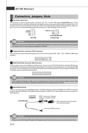
..., 1.2M, 1.44M and 2.88M floppy disk types. 6 ATA133 Hard Disk Connector (IDE connector) A IDE connector can connect a Master and a Slave drive. The CPU FAN supports Smart FAN function. SATA 2.0 connector supports serial ATA data rates of the fan control. En-6 When connect the wire to the connectors, always take advantage of 300 MB...
..., 1.2M, 1.44M and 2.88M floppy disk types. 6 ATA133 Hard Disk Connector (IDE connector) A IDE connector can connect a Master and a Slave drive. The CPU FAN supports Smart FAN function. SATA 2.0 connector supports serial ATA data rates of the fan control. En-6 When connect the wire to the connectors, always take advantage of 300 MB...
User Guide
Page 17
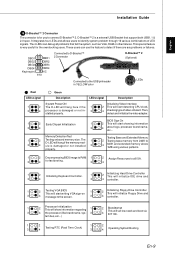
... initialize IDE drive and 3 4 3 4 controller. 1 2 Testing VGA BIOS 1 2 Initializing Floppy Drive Controller This will start detecting CPU clock, 4 checking type ofvideo onboard. properly. 1 2 Decompressing BIOS image to RAM 1 2 Assign Resources to all problems that support both USB1.1 & 2.0 spec. The 1 2 Testing base memory from 240K to identify system problem through 16 various combinations...
... initialize IDE drive and 3 4 3 4 controller. 1 2 Testing VGA BIOS 1 2 Initializing Floppy Drive Controller This will start detecting CPU clock, 4 checking type ofvideo onboard. properly. 1 2 Decompressing BIOS image to RAM 1 2 Assign Resources to all problems that support both USB1.1 & 2.0 spec. The 1 2 Testing base memory from 240K to identify system problem through 16 various combinations...


