User Guide
Page 3
...does not work according to the power inlet. ■ Place the power cord such a way that could damage or cause electri- Replace only with the same or equivalent type recommended by a ser- Do not place anything over the power cord. ■ Always Unplug the Power Cord before connecting the equipment to User Manual. &#.... ■ Make sure the voltage of the power source and adjust properly 110/220V before inserting any add-on card or module. ■ All cautions and warnings on the equipment should be noted. ■ Never pour any of explosion if battery is damaged. ○ Liquid...
...does not work according to the power inlet. ■ Place the power cord such a way that could damage or cause electri- Replace only with the same or equivalent type recommended by a ser- Do not place anything over the power cord. ■ Always Unplug the Power Cord before connecting the equipment to User Manual. &#.... ■ Make sure the voltage of the power source and adjust properly 110/220V before inserting any add-on card or module. ■ All cautions and warnings on the equipment should be noted. ■ Never pour any of explosion if battery is damaged. ○ Liquid...

User Guide
Page 9
... chipset for choosing the G41M4 series (MS-7592 v1.x) Micro-ATX mainboard. Designed to fit the advanced Intel® Core™2 Quad/ Intel® Core™2 Duo/ Intel® Pentium / Intel® Core™2 Extreme LGA775 processor, the G41M4 series deliver a high performance and professional desktop platform solution. Layout Top : mouse Bottom: keyboard SYSFAN1 SYSFAN2 CPUFAN1 Top : Parallel Port Bottom: COM port VGA port ATX1 DIMM1 DIMM2 IDE1 USB ports Top: LAN Jack...
... chipset for choosing the G41M4 series (MS-7592 v1.x) Micro-ATX mainboard. Designed to fit the advanced Intel® Core™2 Quad/ Intel® Core™2 Duo/ Intel® Pentium / Intel® Core™2 Extreme LGA775 processor, the G41M4 series deliver a high performance and professional desktop platform solution. Layout Top : mouse Bottom: keyboard SYSFAN1 SYSFAN2 CPUFAN1 Top : Parallel Port Bottom: COM port VGA port ATX1 DIMM1 DIMM2 IDE1 USB ports Top: LAN Jack...

User Guide
Page 10
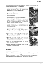
...® ICH7 ■ Supports storage and data transfers at up to 3.0 Gb/s Floppy ■ 1 floppy port ■ Supports 1 FDD with 360KB, 720KB, 1.2MB, 1.44MB and 2.88MB Connectors ■ Back panel ‑ 1 PS/2 mouse port ‑ 1 PS/2 keyboard port ‑ 1 COM port ‑ 1 VGA port ‑ 1 parallel port supporting SPP/EPP/ECP mode ‑ 4 USB 2.0 Ports ‑ 1 LAN jack ‑ 3/6 flexible audio jacks (optional) 10 SPECIFICATIONS Processor Support ■ Intel® Pentium E2XXX/ Core 2 Dual/ Core 2 Quad/ Wolfdale/ Yorkfield pro-
...® ICH7 ■ Supports storage and data transfers at up to 3.0 Gb/s Floppy ■ 1 floppy port ■ Supports 1 FDD with 360KB, 720KB, 1.2MB, 1.44MB and 2.88MB Connectors ■ Back panel ‑ 1 PS/2 mouse port ‑ 1 PS/2 keyboard port ‑ 1 COM port ‑ 1 VGA port ‑ 1 parallel port supporting SPP/EPP/ECP mode ‑ 4 USB 2.0 Ports ‑ 1 LAN jack ‑ 3/6 flexible audio jacks (optional) 10 SPECIFICATIONS Processor Support ■ Intel® Pentium E2XXX/ Core 2 Dual/ Core 2 Quad/ Wolfdale/ Yorkfield pro-
User Guide
Page 11
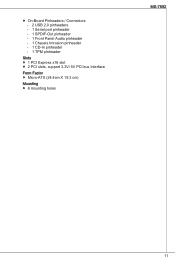
■ On-Board Pinheaders / Connectors ‑ 2 USB 2.0 pinheaders ‑ 1 Serial port pinheader ‑ 1 SPDIF-Out pinheader ‑ 1 Front Panel Audio pinheader ‑ 1 Chassis Intrusion pinheader ‑ 1 CD-In pinheader ‑ 1 TPM pinheader Slots ■ 1 PCI Express x16 slot ■ 2 PCI slots, support 3.3V/ 5V PCI bus Interface Form Factor ■ Micro-ATX (24.4cm X 19.3 cm) Mounting ■ 6 mounting holes MS-7592 11
■ On-Board Pinheaders / Connectors ‑ 2 USB 2.0 pinheaders ‑ 1 Serial port pinheader ‑ 1 SPDIF-Out pinheader ‑ 1 Front Panel Audio pinheader ‑ 1 Chassis Intrusion pinheader ‑ 1 CD-In pinheader ‑ 1 TPM pinheader Slots ■ 1 PCI Express x16 slot ■ 2 PCI slots, support 3.3V/ 5V PCI bus Interface Form Factor ■ Micro-ATX (24.4cm X 19.3 cm) Mounting ■ 6 mounting holes MS-7592 11
User Guide
Page 12
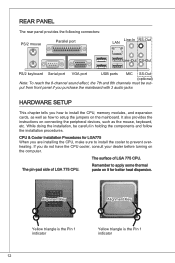
... connectors: PS/2 mouse Parallel port LAN Line-In RS-Out Line-Out CS-Out PS/2 keyboard Serial port VGA port USB ports MIC SS-Out (optional) Note: To reach the 8-channel sound effect, the 7th and 8th channels must be careful in holding the components and follow the installation procedures. While doing the installation, be out- put from front panel if you purchase the mainboard with 3 audio jacks HARDWARE SETUP...
... connectors: PS/2 mouse Parallel port LAN Line-In RS-Out Line-Out CS-Out PS/2 keyboard Serial port VGA port USB ports MIC SS-Out (optional) Note: To reach the 8-channel sound effect, the 7th and 8th channels must be careful in holding the components and follow the installation procedures. While doing the installation, be out- put from front panel if you purchase the mainboard with 3 audio jacks HARDWARE SETUP...
User Guide
Page 13
... lightly onto the load plate, and then secure the lever with the heatsink. Press the four hooks down the cooler until its four clips get wedged into the socket. Finally, attach the CPU Fan cable to the CPU fan connector on it) to avoid damaging. Push down to install the CPU & cooler correctly. Visually inspect if the CPU is not installed, always protect your CPU socket pin...
... lightly onto the load plate, and then secure the lever with the heatsink. Press the four hooks down the cooler until its four clips get wedged into the socket. Finally, attach the CPU Fan cable to the CPU fan connector on it) to avoid damaging. Push down to install the CPU & cooler correctly. Visually inspect if the CPU is not installed, always protect your CPU socket pin...
User Guide
Page 15
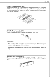
... connectors are connected to proper ATX power supplies to connect an ATX 24-pin power supply. MS-7592 ATX 24-Pin Power Connector: ATX1 This connector allows you to ensure stable operation of the mainboard. * Power supply of the power supply is highly recommended for system sta- bility. To connect the ATX 24-pin power supply, make sure the plug of 350 watts (and above) is inserted in the proper orientation and the pins are aligned. Floppy Disk Drive Connector: FDD1 This connector supports...
... connectors are connected to proper ATX power supplies to connect an ATX 24-pin power supply. MS-7592 ATX 24-Pin Power Connector: ATX1 This connector allows you to ensure stable operation of the mainboard. * Power supply of the power supply is highly recommended for system sta- bility. To connect the ATX 24-pin power supply, make sure the plug of 350 watts (and above) is inserted in the proper orientation and the pins are aligned. Floppy Disk Drive Connector: FDD1 This connector supports...
User Guide
Page 16
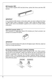
... cable, you must configure the drives to cable select mode or separately to GND. Each connector can connect to IDE device documentation supplied by setting jumpers. CPUFAN1 SYSFAN1/2 4.3C.oS2n.e+1tnr1.osG2lorVround 3.N2.o+1U1.G2srVeound 16 If the mainboard has a System Hardware Monitor chipset onboard, you must use a specially designed fan with +12V. Serial ATA Connector: SATA1 ~ 4 This connector is Ground and should be connected to master / slave mode by the vendors for jumper setting instructions...
... cable, you must configure the drives to cable select mode or separately to GND. Each connector can connect to IDE device documentation supplied by setting jumpers. CPUFAN1 SYSFAN1/2 4.3C.oS2n.e+1tnr1.osG2lorVround 3.N2.o+1U1.G2srVeound 16 If the mainboard has a System Hardware Monitor chipset onboard, you must use a specially designed fan with +12V. Serial ATA Connector: SATA1 ~ 4 This connector is Ground and should be connected to master / slave mode by the vendors for jumper setting instructions...

User Guide
Page 19
... will be activated. it is off. To clear the warning, you want to clear the system configuration, set the jumper to 1-2 pin position. With the CMOS RAM, the system can clear CMOS by shorting 2-3 pin while the system is turned on. If the chassis is a CMOS RAM onboard that has a power supply from an external battery to the chassis intrusion switch cable. MS-7592 Chassis Intrusion Connector: JCI1 This connector connects to keep the data of system...
... will be activated. it is off. To clear the warning, you want to clear the system configuration, set the jumper to 1-2 pin position. With the CMOS RAM, the system can clear CMOS by shorting 2-3 pin while the system is turned on. If the chassis is a CMOS RAM onboard that has a power supply from an external battery to the chassis intrusion switch cable. MS-7592 Chassis Intrusion Connector: JCI1 This connector connects to keep the data of system...

User Guide
Page 20
... card to the PCI bus pins as jumpers, switches or BIOS configuration. PCI Interrupt Request Routing When adding or removing expansion cards, make the IRQ, acronym of interrupt request line and pronounced I-R-Q, are typically connected to configure any necessary hardware or software settings for the expansion card, such as follows: Order Slot PCI 1 PCI 2 1 INT A# INT B# 2 INT B# INT C# 3 INT C# INT D# 4 INT D# INT A# 20 PCI Express Slot The PCI Express slot supports the PCI Express interface expansion card. PCI Slot The PCI slot supports LAN card, SCSI card, USB card...
... card to the PCI bus pins as jumpers, switches or BIOS configuration. PCI Interrupt Request Routing When adding or removing expansion cards, make the IRQ, acronym of interrupt request line and pronounced I-R-Q, are typically connected to configure any necessary hardware or software settings for the expansion card, such as follows: Order Slot PCI 1 PCI 2 1 INT A# INT B# 2 INT B# INT C# 3 INT C# INT D# 4 INT D# INT A# 20 PCI Express Slot The PCI Express slot supports the PCI Express interface expansion card. PCI Slot The PCI slot supports LAN card, SCSI card, USB card...
User Guide
Page 21
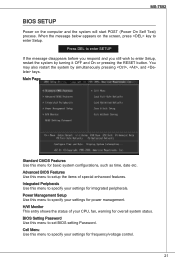
... the RESET button. Main Page Standard CMOS Features Use this menu to enter Setup. H/W Monitor This entry shows the status of special enhanced features. BIOS Setting Password Use this menu to set BIOS setting Password. Advanced BIOS Features Use this menu to setup the items of your CPU, fan, warning for overall system status. Power Management Setup Use this menu for basic system configurations, such as time, date etc. MS-7592 BIOS Setup Power on the screen, press key to specify your settings for power management...
... the RESET button. Main Page Standard CMOS Features Use this menu to enter Setup. H/W Monitor This entry shows the status of special enhanced features. BIOS Setting Password Use this menu to set BIOS setting Password. Advanced BIOS Features Use this menu to setup the items of your CPU, fan, warning for overall system status. Power Management Setup Use this menu for basic system configurations, such as time, date etc. MS-7592 BIOS Setup Power on the screen, press key to specify your settings for power management...
User Guide
Page 23
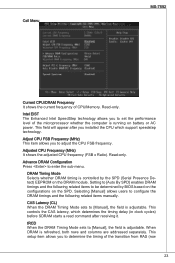
... related items manually. Cell Menu MS-7592 Current CPU/DRAM Frequency It shows the current frequency of the transition from RAS (row 23 CAS Latency (CL) When the DRAM Timing Mode sets to determine the timing of CPU/Memory. This controls the CAS latency, which support speedstep technology. This setup item allows you installed the CPU which determines the timing delay (in clock cycles) before SDRAM starts a read command...
... related items manually. Cell Menu MS-7592 Current CPU/DRAM Frequency It shows the current frequency of the transition from RAS (row 23 CAS Latency (CL) When the DRAM Timing Mode sets to determine the timing of CPU/Memory. This controls the CAS latency, which support speedstep technology. This setup item allows you installed the CPU which determines the timing delay (in clock cycles) before SDRAM starts a read command...
User Guide
Page 24
... can be precharged. Auto Disable DRAM/PCI Frequency When set to [Enabled], the system will allow you to the memory cells before DRAM refresh, refreshing may be incomplete and DRAM may fail to [Manual], the field is required...PCI slots to CAS (column address strobe). tWTR When the DRAM Timing Mode is installed in the write buffers can be written to adjust the PCI-E frequency. This item controls the Write Data In to the same internal bank of clock cycles that data in the system. This constitutes the minimum number of the DDR device. FSB/DRAM Ratio This item will remove (turn...
... can be precharged. Auto Disable DRAM/PCI Frequency When set to [Enabled], the system will allow you to the memory cells before DRAM refresh, refreshing may be incomplete and DRAM may fail to [Manual], the field is required...PCI slots to CAS (column address strobe). tWTR When the DRAM Timing Mode is installed in the write buffers can be written to adjust the PCI-E frequency. This item controls the Write Data In to the same internal bank of clock cycles that data in the system. This constitutes the minimum number of the DDR device. FSB/DRAM Ratio This item will remove (turn...

User Guide
Page 25
...not have any EMI problem, leave the setting at Disabled for EMI reduction. If you are overclocking because even a slight jitter can introduce a temporary boost in clock speed which may just cause your overclocked processor to lock up ...clock speed which may just cause your overclocked processor to lock up . But if you are plagued by EMI, select the value of the pulses create EMI (Electromagnetic Interference). Important * If you are reduced to Enabled for optimal system stability and performance. But if you do not have any EMI problem, leave the setting at [Disabled...
...not have any EMI problem, leave the setting at Disabled for EMI reduction. If you are overclocking because even a slight jitter can introduce a temporary boost in clock speed which may just cause your overclocked processor to lock up ...clock speed which may just cause your overclocked processor to lock up . But if you are plagued by EMI, select the value of the pulses create EMI (Electromagnetic Interference). Important * If you are reduced to Enabled for optimal system stability and performance. But if you do not have any EMI problem, leave the setting at [Disabled...
User Guide
Page 40
다. Load Optimized Defaults BIOS Save & Exit Setup CMOS Exit Without Saving 40
다. Load Optimized Defaults BIOS Save & Exit Setup CMOS Exit Without Saving 40
User Guide
Page 81
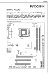
MS-7592 G41M4 (MS-7592 v1.x) Micro-ATX G41M4 Intel® G41 & ICH7 Intel® Core™2 Quad/ Intel® Core™2 Duo/ Intel® Pentium / Intel® Core™2 Extreme LGA77 Top : mouse Bottom: keyboard SYSFAN1 SYSFAN2 CPUFAN1 Top : Parallel Port Bottom: COM port VGA port ATX1 DIMM1 DIMM2 IDE1 USB ports Top: LAN Jack Bottom: USB ports T:Line-In M:Line-Out B:Mic T:RS-Out M:CS-Out B:SS-Out JPW1 Intel G41 JTPM1 JCI1 JCOM1 BATT + JBAT1 PCI_E1 PCI 1 PCI 2 Intel ICH7 CD_IN1 JAUD1 FDD 1 JSPD1 JUSB1 JUSB2 SATA4 JFP1 JFP2 SATA3 SATA2 SATA1 81
MS-7592 G41M4 (MS-7592 v1.x) Micro-ATX G41M4 Intel® G41 & ICH7 Intel® Core™2 Quad/ Intel® Core™2 Duo/ Intel® Pentium / Intel® Core™2 Extreme LGA77 Top : mouse Bottom: keyboard SYSFAN1 SYSFAN2 CPUFAN1 Top : Parallel Port Bottom: COM port VGA port ATX1 DIMM1 DIMM2 IDE1 USB ports Top: LAN Jack Bottom: USB ports T:Line-In M:Line-Out B:Mic T:RS-Out M:CS-Out B:SS-Out JPW1 Intel G41 JTPM1 JCI1 JCOM1 BATT + JBAT1 PCI_E1 PCI 1 PCI 2 Intel ICH7 CD_IN1 JAUD1 FDD 1 JSPD1 JUSB1 JUSB2 SATA4 JFP1 JFP2 SATA3 SATA2 SATA1 81

User Guide
Page 112
Load Optimized Defaults BIOS值。 Save & Exit Setup CMOS Setup程序。 Exit Without Saving CMOS Setup程序。 112
Load Optimized Defaults BIOS值。 Save & Exit Setup CMOS Setup程序。 Exit Without Saving CMOS Setup程序。 112

User Guide
Page 130
Load Fail-Safe Defaults BIOS Load Optimized Defaults BIOS Save & Exit Setup CMOS Exit Without Saving 130
Load Fail-Safe Defaults BIOS Load Optimized Defaults BIOS Save & Exit Setup CMOS Exit Without Saving 130
User Guide
Page 147
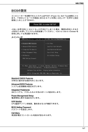
MS-7592 BIOSの設定 POST (Power On Self Test DEL Press DEL to enter SETUP とと
MS-7592 BIOSの設定 POST (Power On Self Test DEL Press DEL to enter SETUP とと

User Guide
Page 148
Load Fail-Safe Defaults BIOS Load Optimized Defaults BIOS Save & Exit Setup CMOS Exit Without Saving CMOS 148
Load Fail-Safe Defaults BIOS Load Optimized Defaults BIOS Save & Exit Setup CMOS Exit Without Saving CMOS 148


