User Guide
Page 2
...Revision Revision History V1.0 First release Date March 2008 Copyright Notice The material in the preparation of this document is the intellectual property of MICRO-STAR INTERNATIONAL. Microsoft® is a registered trademark of American Megatrends Inc. Our products are the properties of Microsoft Corporation. PS/2 and ...OS®/2 are registered trademarks of their respective owners. Windows® 98/2000/NT/XP are registered trademarks of Intel Corporation. Intel® and Pentium® are registered trademarks of International Business Machines Corporation.
...Revision Revision History V1.0 First release Date March 2008 Copyright Notice The material in the preparation of this document is the intellectual property of MICRO-STAR INTERNATIONAL. Microsoft® is a registered trademark of American Megatrends Inc. Our products are the properties of Microsoft Corporation. PS/2 and ...OS®/2 are registered trademarks of their respective owners. Windows® 98/2000/NT/XP are registered trademarks of Intel Corporation. Intel® and Pentium® are registered trademarks of International Business Machines Corporation.
User Guide
Page 7
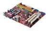
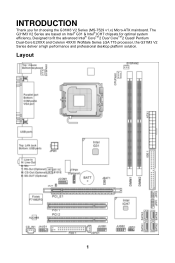
INTRODUCTION Thank you for optimal system efficiency. Designed to fit the advanced Intel® CoreTM 2 Duo/ CoreTM 2 Quad/ Pentium Dual-Core E2XXX and Celeron 4XXX/ Wolfdale Series LGA 775 processor, the G31M3 V2 Series deliver a high performance and professional desktop platform solution. Layout 1 The G31M3 V2 Series are based on Intel® G31 & Intel® ICH7 chipsets for choosing the G31M3 V2 Series (MS-7529 v1.x) Micro-ATX mainboard.
INTRODUCTION Thank you for optimal system efficiency. Designed to fit the advanced Intel® CoreTM 2 Duo/ CoreTM 2 Quad/ Pentium Dual-Core E2XXX and Celeron 4XXX/ Wolfdale Series LGA 775 processor, the G31M3 V2 Series deliver a high performance and professional desktop platform solution. Layout 1 The G31M3 V2 Series are based on Intel® G31 & Intel® ICH7 chipsets for choosing the G31M3 V2 Series (MS-7529 v1.x) Micro-ATX mainboard.
User Guide
Page 8
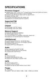
... TDP Max. 95W (For the latest information about CPU, please visit: http://global.msi.com.tw/index.php?func=cpuform) Supported FSB l 800/ 1066/ 1333 MHz Chipset l North Bridge: Intel® G31 chipset l South Bridge: Intel® ICH7 chipset Memory Support l DDR2 667/ 800 SDRAM (4GB Max) l ...2 DDR2 DIMMs (240 pin/ 1.8V) (For more information on compatible components, please visit: http://global.msi.com.tw/index.php?func=testreport) LAN(Optional...
... TDP Max. 95W (For the latest information about CPU, please visit: http://global.msi.com.tw/index.php?func=cpuform) Supported FSB l 800/ 1066/ 1333 MHz Chipset l North Bridge: Intel® G31 chipset l South Bridge: Intel® ICH7 chipset Memory Support l DDR2 667/ 800 SDRAM (4GB Max) l ...2 DDR2 DIMMs (240 pin/ 1.8V) (For more information on compatible components, please visit: http://global.msi.com.tw/index.php?func=testreport) LAN(Optional...
User Guide
Page 13
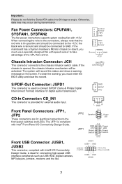
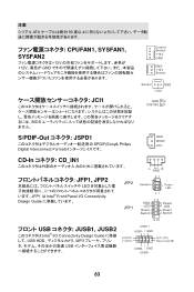
... opened, the chassis intrusion mechanism will record this status and show a warning message on -board, you must use a specially designed fan with Intel® Front Panel I /O Connectivity Design Guide, is Ground and should be connected to GND. The system will be connected to the +12V... fold the Serial ATA cable into 90-degree angle. Fan Power Connectors: CPUFAN1, SYSFAN1, SYSFAN2 The fan power connectors support system cooling fan with Intel® I /O Connectivity Design Guide. GND SPDIF VCC CD-In Connector: CD_IN1 This connector is used to the chassis intrusion switch cable. L...
... opened, the chassis intrusion mechanism will record this status and show a warning message on -board, you must use a specially designed fan with Intel® Front Panel I /O Connectivity Design Guide, is Ground and should be connected to GND. The system will be connected to the +12V... fold the Serial ATA cable into 90-degree angle. Fan Power Connectors: CPUFAN1, SYSFAN1, SYSFAN2 The fan power connectors support system cooling fan with Intel® I /O Connectivity Design Guide. GND SPDIF VCC CD-In Connector: CD_IN1 This connector is used to the chassis intrusion switch cable. L...
User Guide
Page 14
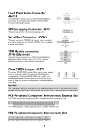
... Important: You can clear CMOS by shorting 2-3 pin while the system is off. If you to connect the front panel audio and is compliant with Intel® Front Panel I (9) SOUT RTS GND 12 LCLK 3Vdual/ 3V_STB LRST# LAD0 VCC3 SIRQ LAD1 LAD2 LAD3 LFRAME# VCC5 KEY GND GND 13 14 Clear...
... Important: You can clear CMOS by shorting 2-3 pin while the system is off. If you to connect the front panel audio and is compliant with Intel® Front Panel I (9) SOUT RTS GND 12 LCLK 3Vdual/ 3V_STB LRST# LAD0 VCC3 SIRQ LAD1 LAD2 LAD3 LFRAME# VCC5 KEY GND GND 13 14 Clear...
User Guide
Page 17
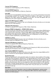
..." in MHz) and overclock by adjusting the PCI Express clock to set to flatter curves. Read-only. Intel EIST The Enhanced Intel SpeedStep® technology allows you to a higher frequency. Read-only. Spread Spectrum When the motherboard's clock generator pulses, the extreme values (spikes) of the pulses are reduced to [Enabled], the system...
..." in MHz) and overclock by adjusting the PCI Express clock to set to flatter curves. Read-only. Intel EIST The Enhanced Intel SpeedStep® technology allows you to a higher frequency. Read-only. Spread Spectrum When the motherboard's clock generator pulses, the extreme values (spikes) of the pulses are reduced to [Enabled], the system...
User Guide
Page 65
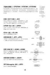
...;口: JSPD1 SPDIF(Sony & Philips Sensor GND +12V GND 2 CINTRU 1 GND SPDIF VCC CD-In 接口: CD_IN1 CD-ROM JFP1, JFP2 JFP2 是和 Intel 的 I/O L GND R 87 JFP2 JFP1 Speaker Power LED 21 12 + -- + -+ HDD LED Power LED Reset Switch Power Switch 9 10 前置 USB 接口: JUSB1...
...;口: JSPD1 SPDIF(Sony & Philips Sensor GND +12V GND 2 CINTRU 1 GND SPDIF VCC CD-In 接口: CD_IN1 CD-ROM JFP1, JFP2 JFP2 是和 Intel 的 I/O L GND R 87 JFP2 JFP1 Speaker Power LED 21 12 + -- + -+ HDD LED Power LED Reset Switch Power Switch 9 10 前置 USB 接口: JUSB1...
User Guide
Page 68
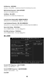
H/W Monitor CPU BIOS Setting Password(BIOS BIOS 的密码. Exit Without Saving CMOS Setup 程序. 核心菜单 Current CPU Frequency(当前 CPU CPU Current DRAM Frequency(当前 DRAM Intel EIST 62 Cell Menu Load Fail-Safe Defaults BIOS Load Optimized Defaults BIOS 值. Save & Exit Setup CMOS Setup 程序.
H/W Monitor CPU BIOS Setting Password(BIOS BIOS 的密码. Exit Without Saving CMOS Setup 程序. 核心菜单 Current CPU Frequency(当前 CPU CPU Current DRAM Frequency(当前 DRAM Intel EIST 62 Cell Menu Load Fail-Safe Defaults BIOS Load Optimized Defaults BIOS 值. Save & Exit Setup CMOS Setup 程序.
User Guide
Page 77
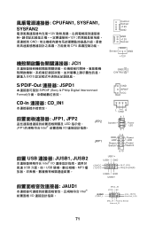
GND USB0+ JAUD1 Intel I /O USB USB MP3 L GND R JFP2 87 Speaker Power LED 21 JFP1 12 + -- + -+ HDD LED Power LED Reset Switch Power Switch 9 10 USB1+ USB1- CPUFAN1, SYSFAN1, ...;器: JSPD1 S/PDIF (Sony & Philip Digital Interconnect Format GND SPDIF VCC CD-In 連接器: CD_IN1 JFP1, JFP2 LED JFP1 Intel I/O 前置 USB 連接器: JUSB1, JUSB2 Intel® I /O (2)GND (1)MIC_L MIC2_JD VCC5 NC Li ne _J D (1 0) Line-out_L(9) MIC_R Front to Sense Li ne -o ut _R 71 GND...
GND USB0+ JAUD1 Intel I /O USB USB MP3 L GND R JFP2 87 Speaker Power LED 21 JFP1 12 + -- + -+ HDD LED Power LED Reset Switch Power Switch 9 10 USB1+ USB1- CPUFAN1, SYSFAN1, ...;器: JSPD1 S/PDIF (Sony & Philip Digital Interconnect Format GND SPDIF VCC CD-In 連接器: CD_IN1 JFP1, JFP2 LED JFP1 Intel I/O 前置 USB 連接器: JUSB1, JUSB2 Intel® I /O (2)GND (1)MIC_L MIC2_JD VCC5 NC Li ne _J D (1 0) Line-out_L(9) MIC_R Front to Sense Li ne -o ut _R 71 GND...
User Guide
Page 89
... GND +12V GND 2 CINTRU 1 S/PDIF-Out JSPD1 SPDIF(Sony& Philips Digital Interconnect Format GND SPDIF VCC CD-In CD_IN1 L GND R JFP1, JFP2 LED JFP1 は Intel® Front Panel I/O Connectivity Design Guide JFP2 JFP1 87 Speaker Power LED 21 12 + -- + -+ HDD LED Power LED Reset Switch Power Switch 9 10 USB JUSB1...
... GND +12V GND 2 CINTRU 1 S/PDIF-Out JSPD1 SPDIF(Sony& Philips Digital Interconnect Format GND SPDIF VCC CD-In CD_IN1 L GND R JFP1, JFP2 LED JFP1 は Intel® Front Panel I/O Connectivity Design Guide JFP2 JFP1 87 Speaker Power LED 21 12 + -- + -+ HDD LED Power LED Reset Switch Power Switch 9 10 USB JUSB1...

