
User Guide
Page 2
Trademarks All trademarks are registered trademarks of AMD® Corporation. Netware® is the intellectual property of MICRO-STAR INTERNATIONAL. Revision History Revision Revision History V1.0 First release Date March 2008 Copyright Notice The material in this ...PS/2 and OS®/2 are registered trademarks of International Business Machines Corporation. PCMCIA and CardBus are registered trademarks of the Personal Computer Memory Card International Association. Windows® 98/2000/NT/XP are under continual improvement and we reserve the right to the correctness of ...
Trademarks All trademarks are registered trademarks of AMD® Corporation. Netware® is the intellectual property of MICRO-STAR INTERNATIONAL. Revision History Revision Revision History V1.0 First release Date March 2008 Copyright Notice The material in this ...PS/2 and OS®/2 are registered trademarks of International Business Machines Corporation. PCMCIA and CardBus are registered trademarks of the Personal Computer Memory Card International Association. Windows® 98/2000/NT/XP are under continual improvement and we reserve the right to the correctness of ...
User Guide
Page 8
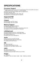
... 95W (For the latest information about CPU, please visit: http://global.msi.com.tw/index.php?func=cpuform) Supported FSB l 800/ 1066/ 1333 MHz Chipset l North Bridge: Intel® G31 chipset l South Bridge: Intel® ICH7 chipset Memory Support l DDR2 667/ 800 SDRAM (4GB Max) l 2 DDR2 DIMMs... (240 pin/ 1.8V) (For more information on compatible components, please visit: http://global.msi.com.tw/index.php?func=testreport) LAN(Optional) l Supports Realtek® ...
... 95W (For the latest information about CPU, please visit: http://global.msi.com.tw/index.php?func=cpuform) Supported FSB l 800/ 1066/ 1333 MHz Chipset l North Bridge: Intel® G31 chipset l South Bridge: Intel® ICH7 chipset Memory Support l DDR2 667/ 800 SDRAM (4GB Max) l 2 DDR2 DIMMs... (240 pin/ 1.8V) (For more information on compatible components, please visit: http://global.msi.com.tw/index.php?func=testreport) LAN(Optional) l Supports Realtek® ...
User Guide
Page 10
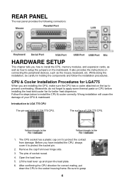
... surface of LGA 775 CPU. REAR PANEL The rear panel provides the following connectors: HARDWARE SETUP This chapter tells you how to install the CPU, memory modules, and expansion cards, as well as the mouse, keyboard, etc.
... surface of LGA 775 CPU. REAR PANEL The rear panel provides the following connectors: HARDWARE SETUP This chapter tells you how to install the CPU, memory modules, and expansion cards, as well as the mouse, keyboard, etc.
User Guide
Page 11
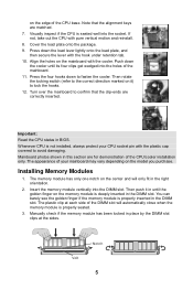
... of the CPU base. Turn over the mainboard to avoid damaging. The appearance of the DIMM slot will only fit in the right orientation. 2. The memory module has only one notch on the model you purchase. The plastic clip at the sides. Manually check if the... CPU status in place by the DIMM slot clips at each side of your CPU socket pin with the cooler. Align the holes on the memory module is not installed, always protect your mainboard may vary depending on the center and will automatically close when the...
... of the CPU base. Turn over the mainboard to avoid damaging. The appearance of the DIMM slot will only fit in the right orientation. 2. The memory module has only one notch on the model you purchase. The plastic clip at the sides. Manually check if the... CPU status in place by the DIMM slot clips at each side of your CPU socket pin with the cooler. Align the holes on the memory module is not installed, always protect your mainboard may vary depending on the center and will automatically close when the...
User Guide
Page 12
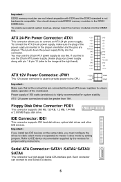
...slots. To enable successful system boot-up, always insert the memory modules into the connector. ATX 12V power connection should always install DDR2 memory modules in the proper orientation and the pins are connected to proper ATX power supplies to IDE device documentation supplied by setting jumpers. ...To connect the ATX 24-pin power supply, make sure the plug of the power supply is...
...slots. To enable successful system boot-up, always insert the memory modules into the connector. ATX 12V power connection should always install DDR2 memory modules in the proper orientation and the pins are connected to proper ATX power supplies to IDE device documentation supplied by setting jumpers. ...To connect the ATX 24-pin power supply, make sure the plug of the power supply is...
User Guide
Page 17
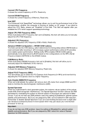
...to flatter curves. Adjusted CPU Frequency It shows the adjusted CPU frequency (FSB x Ratio). Adjusted DDR Memory Frequency It shows the adjusted DDR Memory frequency. Spread Spectrum When the motherboard's clock generator pulses, the extreme values (spikes) of Spread Spectrum for EMI reduction. Read-only.... interference (EMI). Setting to [By SPD] enables DRAM CAS# Latency automatically to manually adjust the FSB/Ratio of the memory. FSB/Memory Ratio When Auto Detect DRAM Frequency item set "Disabled" in clock speed which support speedstep technology. Adjust CPU FSB Frequency ...
...to flatter curves. Adjusted CPU Frequency It shows the adjusted CPU frequency (FSB x Ratio). Adjusted DDR Memory Frequency It shows the adjusted DDR Memory frequency. Spread Spectrum When the motherboard's clock generator pulses, the extreme values (spikes) of Spread Spectrum for EMI reduction. Read-only.... interference (EMI). Setting to [By SPD] enables DRAM CAS# Latency automatically to manually adjust the FSB/Ratio of the memory. FSB/Memory Ratio When Auto Detect DRAM Frequency item set "Disabled" in clock speed which support speedstep technology. Adjust CPU FSB Frequency ...


