
User Manual
Page 13
...Processor 3 Installing DDR4 memory 5 Connecting the Front Panel Header 6 Installing the Motherboard 7 Connecting the Power Connectors 8 Installing SATA Drives 9 Installing a Graphics Card 10 Connecting Peripheral Devices 11 Power On...12 Specifications...15 Package contents 20 Block Diagram ...21 Rear I/O Panel...22 LAN Port LED Status Table 22 Realtek Audio Console 22 Overview of Components 24 Processor Socket 26 DIMM Slots...27 PCI_E1~3: PCIe Expansion Slots 28 SATA1~4: SATA 6Gb/s Connectors 28 M2_1: M.2 Slot (Key M 29 JFP1, JFP2: Front Panel Connectors 31 JAUD1: Front Audio...
...Processor 3 Installing DDR4 memory 5 Connecting the Front Panel Header 6 Installing the Motherboard 7 Connecting the Power Connectors 8 Installing SATA Drives 9 Installing a Graphics Card 10 Connecting Peripheral Devices 11 Power On...12 Specifications...15 Package contents 20 Block Diagram ...21 Rear I/O Panel...22 LAN Port LED Status Table 22 Realtek Audio Console 22 Overview of Components 24 Processor Socket 26 DIMM Slots...27 PCI_E1~3: PCIe Expansion Slots 28 SATA1~4: SATA 6Gb/s Connectors 28 M2_1: M.2 Slot (Key M 29 JFP1, JFP2: Front Panel Connectors 31 JAUD1: Front Audio...

User Manual
Page 14
JRAINBOW1: Addressable RGB LED connectors 38 Installing OS, Drivers & Utilities 39 Installing Windows® 10 39 Installing Drivers 39 Installing Utilities 39 UEFI BIOS...40 BIOS Setup...41 Entering BIOS Setup 41 Resetting BIOS...42 Updating BIOS...42 EZ Mode...44 Advanced Mode ...47 SETTINGS Menu...48 OC Menu...50 M-FLASH Menu...52 OC PROFILE Menu 53 HARDWARE MONITOR Menu 54 AMD RAID Configuration 56 Enabling RAIDXpert2 Configuration Utility 56 Initializing Disks...57 Creating Arrays...58 Deleting Arrays...59 Installing RAID Driver 60 Troubleshooting 61 14 Contents
JRAINBOW1: Addressable RGB LED connectors 38 Installing OS, Drivers & Utilities 39 Installing Windows® 10 39 Installing Drivers 39 Installing Utilities 39 UEFI BIOS...40 BIOS Setup...41 Entering BIOS Setup 41 Resetting BIOS...42 Updating BIOS...42 EZ Mode...44 Advanced Mode ...47 SETTINGS Menu...48 OC Menu...50 M-FLASH Menu...52 OC PROFILE Menu 53 HARDWARE MONITOR Menu 54 AMD RAID Configuration 56 Enabling RAIDXpert2 Configuration Utility 56 Initializing Disks...57 Creating Arrays...58 Deleting Arrays...59 Installing RAID Driver 60 Troubleshooting 61 14 Contents
User Manual
Page 18
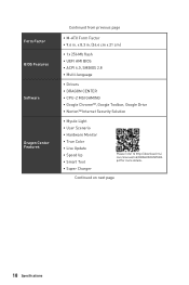
...;UEFI AMI BIOS ∙∙ACPI 6.0, SMBIOS 2.8 ∙∙ Multi-language ∙∙ Drivers ∙∙DRAGON CENTER ∙∙CPU-Z MSI GAMING ∙∙Google Chrome™, Google Toolbar, Google Drive ∙∙Norton™ Internet Security Solution ∙∙Mystic Light ∙∙User Scenario ∙∙Hardware Monitor ∙∙True Color ∙∙Live Update ∙∙Speed...
...;UEFI AMI BIOS ∙∙ACPI 6.0, SMBIOS 2.8 ∙∙ Multi-language ∙∙ Drivers ∙∙DRAGON CENTER ∙∙CPU-Z MSI GAMING ∙∙Google Chrome™, Google Toolbar, Google Drive ∙∙Norton™ Internet Security Solution ∙∙Mystic Light ∙∙User Scenario ∙∙Hardware Monitor ∙∙True Color ∙∙Live Update ∙∙Speed...

User Manual
Page 25
Component Contents Port Name Port Type CPU_FAN1, SYS_FAN1 Fan Connectors CPU_PWR1, ATX_PWR1 Power Connectors DIMMA1, DIMMA2 DIMM Slots JAUD1 Front Audio Connector JBAT1 Clear CMOS (Reset BIOS) Jumper JCI1 Chassis Intrusion Connector JCOM1 Serial Port Connector JFP1, JFP2 Front Panel Connectors JRAINBOW1 Addressable RGB LED connectors JRGB1 RGB LED connectors JTPM1 TPM Module Connector JUSB1~2 USB 2.0 Connectors JUSB3 USB 3.2 Gen 1 5Gbps Connector M2_1 M.2 Slot (Key M) PCI_E1~3 PCIe Expansion Slots Processor Socket AM4 Socket SATA1~4 SATA 6Gb/s Connectors Page...
Component Contents Port Name Port Type CPU_FAN1, SYS_FAN1 Fan Connectors CPU_PWR1, ATX_PWR1 Power Connectors DIMMA1, DIMMA2 DIMM Slots JAUD1 Front Audio Connector JBAT1 Clear CMOS (Reset BIOS) Jumper JCI1 Chassis Intrusion Connector JCOM1 Serial Port Connector JFP1, JFP2 Front Panel Connectors JRAINBOW1 Addressable RGB LED connectors JRGB1 RGB LED connectors JTPM1 TPM Module Connector JUSB1~2 USB 2.0 Connectors JUSB3 USB 3.2 Gen 1 5Gbps Connector M2_1 M.2 Slot (Key M) PCI_E1~3 PCIe Expansion Slots Processor Socket AM4 Socket SATA1~4 SATA 6Gb/s Connectors Page...

User Manual
Page 37
.... 2. Use a jumper cap to clear the CMOS memory. CPU - DRAM - Remove the jumper cap from a battery located on the computer. indicates DRAM is not detected or fail. EZ Debug LED These LEDs indicate the debug status of Components 37 VGA - BOOT - Overview of the motherboard. indicates CPU is not detected or fail. If you want to clear the system configuration, set the jumpers to short JBAT1 for about 5-10 seconds. 3. JBAT1: Clear CMOS (Reset BIOS) Jumper There is CMOS memory onboard...
.... 2. Use a jumper cap to clear the CMOS memory. CPU - DRAM - Remove the jumper cap from a battery located on the computer. indicates DRAM is not detected or fail. EZ Debug LED These LEDs indicate the debug status of Components 37 VGA - BOOT - Overview of the motherboard. indicates CPU is not detected or fail. If you want to clear the system configuration, set the jumpers to short JBAT1 for about 5-10 seconds. 3. JBAT1: Clear CMOS (Reset BIOS) Jumper There is CMOS memory onboard...

User Manual
Page 39
... connector and the JRAINBOW connector provide different voltages, and connecting the 5V LED strip to the JRGB connector will result in damage to the LED strip. ⚠⚠Important ∙∙The JRAINBOW connector supports up to 200 LEDs. ∙∙Always turn off the power supply and unplug the power cord from the power outlet before installing or removing the RGB LED strip. ∙∙Please use MSI's software to control...
... connector and the JRAINBOW connector provide different voltages, and connecting the 5V LED strip to the JRGB connector will result in damage to the LED strip. ⚠⚠Important ∙∙The JRAINBOW connector supports up to 200 LEDs. ∙∙Always turn off the power supply and unplug the power cord from the power outlet before installing or removing the RGB LED strip. ∙∙Please use MSI's software to control...
User Manual
Page 40
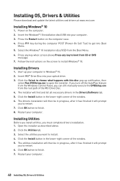
... the Install button in the Drivers/Software tab. 5. Select the utilities you must complete drivers installation. 1. Insert the Windows® 10 installation disc/USB into Boot Menu. 5. Click the Select to install. 4. Installing Utilities Before you install utilities, you want to choose what happens with this disc pop-up your computer in the lower-right corner of the window. 6. Restart your computer. Press F11 key during the computer POST (Power-On...
... the Install button in the Drivers/Software tab. 5. Select the utilities you must complete drivers installation. 1. Insert the Windows® 10 installation disc/USB into Boot Menu. 5. Click the Select to install. 4. Installing Utilities Before you install utilities, you want to choose what happens with this disc pop-up your computer in the lower-right corner of the window. 6. Restart your computer. Press F11 key during the computer POST (Power-On...
User Manual
Page 43
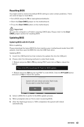
... to BIOS and press F6 to load optimized defaults. ∙∙Short the Clear CMOS jumper on the motherboard. ∙∙Press the Clear CMOS button on the motherboard. ⚠⚠Important Be sure the computer is 100% completed, the system will reboot automatically. Select a BIOS file to activate M-Flash for resetting BIOS. Updating BIOS Updating BIOS with M-FLASH Before updating: Please download the latest BIOS file that contains the update file into the USB flash drive. Press to perform the BIOS update...
... to BIOS and press F6 to load optimized defaults. ∙∙Short the Clear CMOS jumper on the motherboard. ∙∙Press the Clear CMOS button on the motherboard. ⚠⚠Important Be sure the computer is 100% completed, the system will reboot automatically. Select a BIOS file to activate M-Flash for resetting BIOS. Updating BIOS Updating BIOS with M-FLASH Before updating: Please download the latest BIOS file that contains the update file into the USB flash drive. Press to perform the BIOS update...
User Manual
Page 44
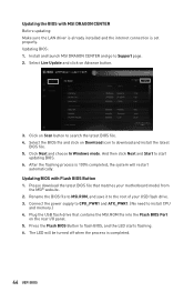
... Advance button. 3. Click Next and choose In Windows mode. And then click Next and Start to install CPU and memory.) 4. Updating BIOS with MSI DRAGON CENTER Before updating: Make sure the LAN driver is already installed and the internet connection is set properly. Please download the latest BIOS file that contains the MSI.ROM file into the Flash BIOS Port on Download icon to the root of your motherboard model from the MSI® website. 2. The LED will be turned off...
... Advance button. 3. Click Next and choose In Windows mode. And then click Next and Start to install CPU and memory.) 4. Updating BIOS with MSI DRAGON CENTER Before updating: Make sure the LAN driver is already installed and the internet connection is set properly. Please download the latest BIOS file that contains the MSI.ROM file into the Flash BIOS Port on Download icon to the root of your motherboard model from the MSI® website. 2. The LED will be turned off...

User Manual
Page 46
... boot priority from high to update BIOS with the motherboard you can save and access favorite/ frequently-used BIOS setting items. 46 UEFI BIOS ∙∙ System information - click on this button to enter the Hardware Monitor menu that provides the way to low is enabled when the button shows ON . ⚠⚠Important The function buttons will vary with a USB flash drive. ∙∙ Hardware Monitor - The function is left to change...
... boot priority from high to update BIOS with the motherboard you can save and access favorite/ frequently-used BIOS setting items. 46 UEFI BIOS ∙∙ System information - click on this button to enter the Hardware Monitor menu that provides the way to low is enabled when the button shows ON . ⚠⚠Important The function buttons will vary with a USB flash drive. ∙∙ Hardware Monitor - The function is left to change...

User Manual
Page 48
... to manage overclocking profiles. ▪▪HARDWARE MONITOR - provides BIOS setting items and information to update BIOS with a USB flash drive. ▪▪OC PROFILE - provides the way to be configured. 48 UEFI BIOS allows you to adjust the frequency and voltage. allows you to set the speeds of fans and monitor voltages of installed devices on this motherboard. ∙∙ Menu display - provides the information of system. ▪▪BOARD EXPLORER - the following options are...
... to manage overclocking profiles. ▪▪HARDWARE MONITOR - provides BIOS setting items and information to update BIOS with a USB flash drive. ▪▪OC PROFILE - provides the way to be configured. 48 UEFI BIOS allows you to adjust the frequency and voltage. allows you to set the speeds of fans and monitor voltages of installed devices on this motherboard. ∙∙ Menu display - provides the information of system. ▪▪BOARD EXPLORER - the following options are...

User Manual
Page 49
..., chipset and boot devices. ▶▶System Status sub-menu The System Status sub-menu allows you to switch between date elements. The format is not displayed, turn off computer and re-check SATA/ M.2 cable and power cable connections of the device and motherboard. ▶▶System Information Shows detailed system information, including CPU type, BIOS version, and Memory (read only). ▶▶DMI Information Shows system information, desktop board information and chassis...
..., chipset and boot devices. ▶▶System Status sub-menu The System Status sub-menu allows you to switch between date elements. The format is not displayed, turn off computer and re-check SATA/ M.2 cable and power cable connections of the device and motherboard. ▶▶System Information Shows detailed system information, including CPU type, BIOS version, and Memory (read only). ▶▶DMI Information Shows system information, desktop board information and chassis...
User Manual
Page 50
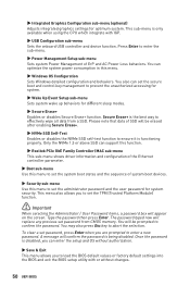
... load the BIOS default values or factory default settings into the BIOS and exit the BIOS setup utility with IGP. ▶▶USB Configuration sub-menu Sets the onboard USB controller and device function. This sub-menu is only available when using the CPU which integrate with or without authorization. ▶▶Save & Exit This menu allows you to confirm the password. Press Enter to set the administrator password and the user password for optimum system. To clear a set password...
... load the BIOS default values or factory default settings into the BIOS and exit the BIOS setup utility with IGP. ▶▶USB Configuration sub-menu Sets the onboard USB controller and device function. This sub-menu is only available when using the CPU which integrate with or without authorization. ▶▶Save & Exit This menu allows you to confirm the password. Press Enter to set the administrator password and the user password for optimum system. To clear a set password...
User Manual
Page 51
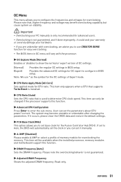
... the overclocking behavior is used to enter the sub-menu. Please note that is not guaranteed. ▶▶Adjusted DRAM Frequency Shows the adjusted DRAM frequency. User can only be available when the installed processor, memory modules and motherboard support this function. ▶▶Advanced CPU Configuration Press Enter to determine CPU clock speed. This item will automatically set the clock or you can set it occurs, please clear the CMOS data and restore the default settings...
... the overclocking behavior is used to enter the sub-menu. Please note that is not guaranteed. ▶▶Adjusted DRAM Frequency Shows the adjusted DRAM frequency. User can only be available when the installed processor, memory modules and motherboard support this function. ▶▶Advanced CPU Configuration Press Enter to determine CPU clock speed. This item will automatically set the clock or you can set it occurs, please clear the CMOS data and restore the default settings...
User Manual
Page 52
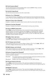
... (Internal memory controller clock) mode. ▶▶Memory Try It ! [Disabled] It can also access this information menu at any time by choosing optimized memory preset. If it manually. ▶▶Memory Changed Detect [Enabled]* Enables or disables the system to issue a warning message during boot when the memory has been replaced. [Enabled] [Disabled] The system will be available when the installed processor supports this function and keeps the current BIOS settings. ▶▶CPU Specifications sub-menu Press Enter...
... (Internal memory controller clock) mode. ▶▶Memory Try It ! [Disabled] It can also access this information menu at any time by choosing optimized memory preset. If it manually. ▶▶Memory Changed Detect [Enabled]* Enables or disables the system to issue a warning message during boot when the memory has been replaced. [Enabled] [Disabled] The system will be available when the installed processor supports this function and keeps the current BIOS settings. ▶▶CPU Specifications sub-menu Press Enter...

User Manual
Page 53
... the steps below to reboot and enter the flash mode. 3. After the flashing process is 100% completed, the system will appear after rebooting. 4. The system will enter the flash mode and a file selection menu will reboot automatically. Click on Yes to update BIOS. 1. UEFI BIOS 53 Select a BIOS file to update BIOS with a USB flash drive. Please download the latest BIOS file that contains the update file into your USB flash drive. M-FLASH Menu M-FLASH provides the way to perform the...
... the steps below to reboot and enter the flash mode. 3. After the flashing process is 100% completed, the system will appear after rebooting. 4. The system will enter the flash mode and a file selection menu will reboot automatically. Click on Yes to update BIOS. 1. UEFI BIOS 53 Select a BIOS file to update BIOS with a USB flash drive. Please download the latest BIOS file that contains the update file into your USB flash drive. M-FLASH Menu M-FLASH provides the way to perform the...
User Manual
Page 57
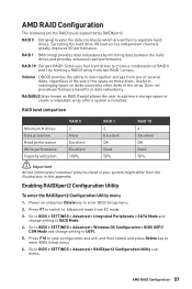
... All the information/ volumes/ pictures listed in your system might differ from two RAID 1 arrays. Go to BIOS > SETTINGS > Advanced > Windows OS Configuration > BIOS UEFI/ CSM Mode and change setting to Advanced mode from EZ mode. 3. AMD RAID Configuration 57 RAIDABLE (also known as RAID Ready) allows the user to BIOS > SETTINGS > Advanced > RAIDXpert2 Configuration Utility submenu. Enabling RAIDXpert2 Configuration Utility To enter the RAIDXpert2 Configuration Utility menu 1. AMD RAID Configuration The following are written to separate hard drives. RAID 0 (Striping) breaks the data...
... All the information/ volumes/ pictures listed in your system might differ from two RAID 1 arrays. Go to BIOS > SETTINGS > Advanced > Windows OS Configuration > BIOS UEFI/ CSM Mode and change setting to Advanced mode from EZ mode. 3. AMD RAID Configuration 57 RAIDABLE (also known as RAID Ready) allows the user to BIOS > SETTINGS > Advanced > RAIDXpert2 Configuration Utility submenu. Enabling RAIDXpert2 Configuration Utility To enter the RAIDXpert2 Configuration Utility menu 1. AMD RAID Configuration The following are written to separate hard drives. RAID 0 (Striping) breaks the data...
User Manual
Page 61
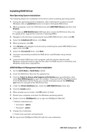
..., and Windows setup starts copying files. exe from the Windows Control Panel, you to restart, click OK button to install a third party RAID driver. 2. When prompted, insert the USB flash drive with the new credentials. Select the (rcbottom.inf) driver, click Next. 5. Set the SATA Mode to the directory containing the saved AMD RAID drivers again, then click OK. 7. Click the Install button. 6. Restart your computer and enter the Windows operating system. 8. Insert the MSI Driver Disc...
..., and Windows setup starts copying files. exe from the Windows Control Panel, you to restart, click OK button to install a third party RAID driver. 2. When prompted, insert the USB flash drive with the new credentials. Select the (rcbottom.inf) driver, click Next. 5. Set the SATA Mode to the directory containing the saved AMD RAID drivers again, then click OK. 7. Click the Install button. 6. Restart your computer and enter the Windows operating system. 8. Insert the MSI Driver Disc...

User Manual
Page 62
... not boot after updating the BIOS ∙∙Clear the CMOS. ∙∙Use the secondary BIOS to lose all customized settings in the DIMMA2 slot first and then restart the computer. ∙∙If 1 long 2 short beeps are heard, remove all ATX power connectors like ATX_PWR1, CPU_PWR1 are connected from the power supply to the motherboard? ∙∙Some power supply units have a power button on the rear side, make sure the LAN port LEDs are...
... not boot after updating the BIOS ∙∙Clear the CMOS. ∙∙Use the secondary BIOS to lose all customized settings in the DIMMA2 slot first and then restart the computer. ∙∙If 1 long 2 short beeps are heard, remove all ATX power connectors like ATX_PWR1, CPU_PWR1 are connected from the power supply to the motherboard? ∙∙Some power supply units have a power button on the rear side, make sure the LAN port LEDs are...
User Manual
Page 66
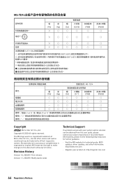
.... The MSI logo used is expressed or implied. MSI reserves the right to make changes to accuracy or completeness is a registered trademark of Micro-Star Int'l Co., Ltd. Revision History Version 1.0, 2020/07, First release. Alternatively, please try the following help resources for technical guide, BIOS updates, driver updates, and other marks and names mentioned may be obtained from the user guide, please...
.... The MSI logo used is expressed or implied. MSI reserves the right to make changes to accuracy or completeness is a registered trademark of Micro-Star Int'l Co., Ltd. Revision History Version 1.0, 2020/07, First release. Alternatively, please try the following help resources for technical guide, BIOS updates, driver updates, and other marks and names mentioned may be obtained from the user guide, please...


