
User Manual
Page 13
... Processor 3 Installing DDR4 memory 5 Connecting the Front Panel Header 6 Installing the Motherboard 7 Connecting the Power Connectors 8 Installing SATA Drives 9 Installing a Graphics Card 10 Connecting Peripheral Devices 11 Power On...12 Specifications...15 Package contents 20 Block Diagram ...21 Rear I/O Panel...22 LAN Port LED Status Table 22 Audio Ports Configuration 22 Realtek Audio Console 23 Overview of Components 25 Processor Socket 27 DIMM Slots...28 PCI_E1~4: PCIe Expansion Slots 29 SATA1~6: SATA 6Gb/s Connectors 30 M2_1~2: M.2 Slots (Key M 30 JFP1, JFP2: Front Panel...
... Processor 3 Installing DDR4 memory 5 Connecting the Front Panel Header 6 Installing the Motherboard 7 Connecting the Power Connectors 8 Installing SATA Drives 9 Installing a Graphics Card 10 Connecting Peripheral Devices 11 Power On...12 Specifications...15 Package contents 20 Block Diagram ...21 Rear I/O Panel...22 LAN Port LED Status Table 22 Audio Ports Configuration 22 Realtek Audio Console 23 Overview of Components 25 Processor Socket 27 DIMM Slots...28 PCI_E1~4: PCIe Expansion Slots 29 SATA1~6: SATA 6Gb/s Connectors 30 M2_1~2: M.2 Slots (Key M 30 JFP1, JFP2: Front Panel...

User Manual
Page 14
... RGB LED connectors 40 EZ Debug LED...41 LED_SW1: EZ LED Control 41 Installing OS, Drivers & Utilities 42 Installing Windows® 10 42 Installing Drivers 42 Installing Utilities 42 UEFI BIOS...43 BIOS Setup...44 Entering BIOS Setup 44 Resetting BIOS...45 Updating BIOS...45 EZ Mode...47 Advanced Mode ...50 SETTINGS Menu...51 OC Menu...53 M-FLASH Menu...55 OC PROFILE Menu 56 HARDWARE MONITOR Menu 57 AMD RAID Configuration 59 Enabling RAIDXpert2 Configuration Utility 59 Initializing Disks...60 Creating Arrays...61 Deleting Arrays...62 Installing RAID Driver 63 Troubleshooting 64...
... RGB LED connectors 40 EZ Debug LED...41 LED_SW1: EZ LED Control 41 Installing OS, Drivers & Utilities 42 Installing Windows® 10 42 Installing Drivers 42 Installing Utilities 42 UEFI BIOS...43 BIOS Setup...44 Entering BIOS Setup 44 Resetting BIOS...45 Updating BIOS...45 EZ Mode...47 Advanced Mode ...50 SETTINGS Menu...51 OC Menu...53 M-FLASH Menu...55 OC PROFILE Menu 56 HARDWARE MONITOR Menu 57 AMD RAID Configuration 59 Enabling RAIDXpert2 Configuration Utility 59 Initializing Disks...60 Creating Arrays...61 Deleting Arrays...62 Installing RAID Driver 63 Troubleshooting 64...
User Manual
Page 15
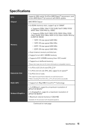
...;∙Supports 2-Way AMD CrossFire™ Technology ∙∙1x HDMI port, supports a maximum resolution of 4096x2160 @24Hz* ∙∙1x DisplayPort, supports a maximum resolution of 4096x2160 @60Hz* ∙∙Maximum shared memory of 2048 MB * Available for the processor with integrated graphics. Specifications CPU Chipset Memory Expansion Slot Multi-GPU Onboard Graphics Supports AM4 socket 3rd Gen AMD Ryzen™ processors, and future AMD Ryzen™ processors with BIOS update AMD B550 Chipset ∙∙4x DDR4 memory slots, support...
...;∙Supports 2-Way AMD CrossFire™ Technology ∙∙1x HDMI port, supports a maximum resolution of 4096x2160 @24Hz* ∙∙1x DisplayPort, supports a maximum resolution of 4096x2160 @60Hz* ∙∙Maximum shared memory of 2048 MB * Available for the processor with integrated graphics. Specifications CPU Chipset Memory Expansion Slot Multi-GPU Onboard Graphics Supports AM4 socket 3rd Gen AMD Ryzen™ processors, and future AMD Ryzen™ processors with BIOS update AMD B550 Chipset ∙∙4x DDR4 memory slots, support...
User Manual
Page 18
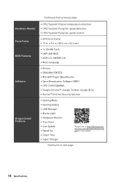
... Hardware Monitor Form Factor BIOS Features Software Dragon Center Features ∙∙CPU/ System/ Chipset temperature detection ∙∙CPU/ System/ Pump fan speed detection ∙∙CPU/ System/ Pump fan speed control ∙∙ATX Form Factor ∙∙12 in . (30.5 cm x 24.4 cm) ∙∙1x 256 Mb flash ∙∙UEFI AMI BIOS ∙∙ACPI 6.0, SMBIOS 2.8 ∙∙ Multi-language ∙∙ Drivers ∙...
... Hardware Monitor Form Factor BIOS Features Software Dragon Center Features ∙∙CPU/ System/ Chipset temperature detection ∙∙CPU/ System/ Pump fan speed detection ∙∙CPU/ System/ Pump fan speed control ∙∙ATX Form Factor ∙∙12 in . (30.5 cm x 24.4 cm) ∙∙1x 256 Mb flash ∙∙UEFI AMI BIOS ∙∙ACPI 6.0, SMBIOS 2.8 ∙∙ Multi-language ∙∙ Drivers ∙...

User Manual
Page 38
...: Serial Port Connector This connector allows you want to clear the system configuration, set the jumpers to clear the CMOS memory. Use a jumper cap to default values 1. If you to connect the optional serial port with bracket. 2 10 1 9 1 DCD 2 SIN 3 SOUT 4 DTR 5 Ground 6 DSR 7 RTS 8 CTS 9 RI 10 No Pin JBAT1: Clear CMOS (Reset BIOS) Jumper There is CMOS memory onboard that is external powered from JBAT1. 4. Keep Data (default) Clear CMOS/ Reset BIOS Resetting BIOS to short JBAT1 for about 5-10 seconds. 3. Remove the jumper cap from a battery located...
...: Serial Port Connector This connector allows you want to clear the system configuration, set the jumpers to clear the CMOS memory. Use a jumper cap to default values 1. If you to connect the optional serial port with bracket. 2 10 1 9 1 DCD 2 SIN 3 SOUT 4 DTR 5 Ground 6 DSR 7 RTS 8 CTS 9 RI 10 No Pin JBAT1: Clear CMOS (Reset BIOS) Jumper There is CMOS memory onboard that is external powered from JBAT1. 4. Keep Data (default) Clear CMOS/ Reset BIOS Resetting BIOS to short JBAT1 for about 5-10 seconds. 3. Remove the jumper cap from a battery located...

User Manual
Page 40
... connector supports up to 200 LEDs. ∙∙Always turn off the power supply and unplug the power cord from the power outlet before installing or removing the RGB LED strip. ∙∙Please use MSI's software to connect the WS2812B Individually Addressable RGB LED strips 5V. 1 1 +5V 2 Data 3 No Pin 4 Ground Addressable RGB LED Strip Connection 1 +5V D JRAINBOW connector Rainbow RGB LED extension cable Addressable RGB LED Fan Connection JRAINBOW connector 1 WS2812B Individually Addressable RGB LED...
... connector supports up to 200 LEDs. ∙∙Always turn off the power supply and unplug the power cord from the power outlet before installing or removing the RGB LED strip. ∙∙Please use MSI's software to connect the WS2812B Individually Addressable RGB LED strips 5V. 1 1 +5V 2 Data 3 No Pin 4 Ground Addressable RGB LED Strip Connection 1 +5V D JRAINBOW connector Rainbow RGB LED extension cable Addressable RGB LED Fan Connection JRAINBOW connector 1 WS2812B Individually Addressable RGB LED...
User Manual
Page 42
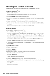
Press any key when screen shows Press any key to boot from the Boot Menu. 6. message. 7. Insert MSI® Drive Disc into your computer. 3. Restart your computer. 42 Installing OS, Drivers & Utilities Click the Install button in the lower-right corner of the window. 5. Restart your computer. Power on the screen to install. 4. Select the Windows® 10 installation disc/USB from CD or DVD... Click the Install button in the lower-right corner...
Press any key when screen shows Press any key to boot from the Boot Menu. 6. message. 7. Insert MSI® Drive Disc into your computer. 3. Restart your computer. 42 Installing OS, Drivers & Utilities Click the Install button in the lower-right corner of the window. 5. Restart your computer. Power on the screen to install. 4. Select the Windows® 10 installation disc/USB from CD or DVD... Click the Install button in the lower-right corner...
User Manual
Page 45
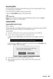
.... 3. Press to activate M-Flash for resetting BIOS. Please refer the following methods to enter flash mode. ▪▪Reboot and press Ctrl + F5 key during POST to enter BIOS. Resetting BIOS You might need to restore the default BIOS setting to solve certain problems. There are several ways to reset BIOS: ∙∙Go to BIOS and press F6 to load optimized defaults. ∙∙Short the Clear CMOS jumper on the motherboard. ⚠⚠Important...
.... 3. Press to activate M-Flash for resetting BIOS. Please refer the following methods to enter flash mode. ▪▪Reboot and press Ctrl + F5 key during POST to enter BIOS. Resetting BIOS You might need to restore the default BIOS setting to solve certain problems. There are several ways to reset BIOS: ∙∙Go to BIOS and press F6 to load optimized defaults. ∙∙Short the Clear CMOS jumper on the motherboard. ⚠⚠Important...

User Manual
Page 46
... the LAN driver is already installed and the internet connection is completed. 46 UEFI BIOS Click on the rear I/O panel. 5. Click Next and choose In Windows mode. And then click Next and Start to flash BIOS, and the LED starts flashing. 6. Plug the USB flash drive that matches your USB flash drive. 3. Select Live Update and click on Download icon to Support page. 2. Press the Flash BIOS Button to start updating BIOS. 6. Rename the BIOS file to MSI.ROM, and save it to install CPU and memory.) 4. The LED...
... the LAN driver is already installed and the internet connection is completed. 46 UEFI BIOS Click on the rear I/O panel. 5. Click Next and choose In Windows mode. And then click Next and Start to flash BIOS, and the LED starts flashing. 6. Plug the USB flash drive that matches your USB flash drive. 3. Select Live Update and click on Download icon to Support page. 2. Press the Flash BIOS Button to start updating BIOS. 6. Rename the BIOS file to MSI.ROM, and save it to install CPU and memory.) 4. The LED...
User Manual
Page 48
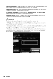
... buttons will vary with a USB flash drive. ∙∙ Hardware Monitor - shows the CPU/ DDR speed, CPU/ MB temperature, MB/ CPU type, memory size, CPU/ DDR voltage, BIOS version and build date. ∙∙ Boot device priority bar - click on this button to enter the Hardware Monitor menu that provides the way to change the boot priority. enable or disable these functions by percentage. ∙∙ Favorites - you purchased. ∙∙ M-Flash - The function is left to manually control the fan speed...
... buttons will vary with a USB flash drive. ∙∙ Hardware Monitor - shows the CPU/ DDR speed, CPU/ MB temperature, MB/ CPU type, memory size, CPU/ DDR voltage, BIOS version and build date. ∙∙ Boot device priority bar - click on this button to enter the Hardware Monitor menu that provides the way to change the boot priority. enable or disable these functions by percentage. ∙∙ Favorites - you purchased. ∙∙ M-Flash - The function is left to manually control the fan speed...

User Manual
Page 50
... chipset and boot devices. ▪▪OC - provides the information of system. ▪▪BOARD EXPLORER - allows you to set the speeds of fans and monitor voltages of installed devices on this motherboard. ∙∙ Menu display - BIOS menu selection BIOS menu selection Menu display ∙∙ BIOS menu selection - Increasing the frequency may get better performance. ▪▪M-FLASH - provides BIOS setting items and information to manage overclocking profiles. ▪▪HARDWARE MONITOR - allows you to update BIOS with a USB flash drive...
... chipset and boot devices. ▪▪OC - provides the information of system. ▪▪BOARD EXPLORER - allows you to set the speeds of fans and monitor voltages of installed devices on this motherboard. ∙∙ Menu display - BIOS menu selection BIOS menu selection Menu display ∙∙ BIOS menu selection - Increasing the frequency may get better performance. ▪▪M-FLASH - provides BIOS setting items and information to manage overclocking profiles. ▪▪HARDWARE MONITOR - allows you to update BIOS with a USB flash drive...

User Manual
Page 51
... of onboard power LED behaviors. ▶▶Integrated Peripherals sub-menu Sets integrated peripherals' parameters, such as LAN, Wi-Fi, HDD, SSD, USB and audio. Read-only. The format is not displayed, turn off computer and re-check SATA/ M.2 cable and power cable connections of the device and motherboard. ▶▶System Information Shows detailed system information, including CPU type, BIOS version, and Memory (read only). ▶▶DMI Information Shows system information, desktop board...
... of onboard power LED behaviors. ▶▶Integrated Peripherals sub-menu Sets integrated peripherals' parameters, such as LAN, Wi-Fi, HDD, SSD, USB and audio. Read-only. The format is not displayed, turn off computer and re-check SATA/ M.2 cable and power cable connections of the device and motherboard. ▶▶System Information Shows detailed system information, including CPU type, BIOS version, and Memory (read only). ▶▶DMI Information Shows system information, desktop board...

User Manual
Page 52
... user password for optimum system. Secure Erase+ is being disabled. You also can enter the setup and OS without changes. 52 UEFI BIOS The password typed now will be erased after enabling Secure Erase+. ▶▶Realtek PCIe GbE Family Controller (MAC sub-menu This sub-menu shows driver information and configuration of the Ethernet controller parameter. ▶▶Boot sub-menu Use this menu to set password from a SSD. ▶▶Integrated Graphics Configuration sub-menu (optional...
... user password for optimum system. Secure Erase+ is being disabled. You also can enter the setup and OS without changes. 52 UEFI BIOS The password typed now will be erased after enabling Secure Erase+. ▶▶Realtek PCIe GbE Family Controller (MAC sub-menu This sub-menu shows driver information and configuration of the Ethernet controller parameter. ▶▶Boot sub-menu Use this menu to set password from a SSD. ▶▶Integrated Graphics Configuration sub-menu (optional...
User Manual
Page 53
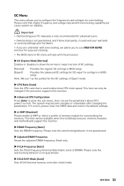
...;The BIOS items in BIOS setup. This item can set the parameters about CPU power/ current. Note: We use CREATOR GENIE function for advanced users. ∙∙Overclocking is used to configure in OC menu will be changed if the processor supports this function. ▶▶DRAM Frequency [Auto] Sets the DRAM frequency. User can only be available when the installed processor, memory modules and motherboard support this function. ▶▶Advanced CPU Configuration Press Enter to configure the frequencies and voltages for...
...;The BIOS items in BIOS setup. This item can set the parameters about CPU power/ current. Note: We use CREATOR GENIE function for advanced users. ∙∙Overclocking is used to configure in OC menu will be changed if the processor supports this function. ▶▶DRAM Frequency [Auto] Sets the DRAM frequency. User can only be available when the installed processor, memory modules and motherboard support this function. ▶▶Advanced CPU Configuration Press Enter to configure the frequencies and voltages for...

User Manual
Page 54
... can set it manually. ▶▶DRAM Voltages control [Auto] These options allows you to set the voltages related to enter the sub-menu. Disables this information menu at any time by pressing [F5]. 54 UEFI BIOS This sub-menu displays the information of installed memory. Read only. ▶▶MEMORY-Z sub-menu Press Enter to load the default settings for memory OC retry. If set to Auto, BIOS will issue a warning message during boot when the memory has been replaced. [Enabled] [Disabled] The...
... can set it manually. ▶▶DRAM Voltages control [Auto] These options allows you to set the voltages related to enter the sub-menu. Disables this information menu at any time by pressing [F5]. 54 UEFI BIOS This sub-menu displays the information of installed memory. Read only. ▶▶MEMORY-Z sub-menu Press Enter to load the default settings for memory OC retry. If set to Auto, BIOS will issue a warning message during boot when the memory has been replaced. [Enabled] [Disabled] The...

User Manual
Page 55
... rebooting. 4. Select a BIOS file to update BIOS. 1. Insert the USB flash drive that matches your USB flash drive. UEFI BIOS 55 And then follow the steps below to perform the BIOS update process. 5. The system will enter the flash mode and a file selection menu will reboot automatically. M-FLASH Menu M-FLASH provides the way to reboot and enter the flash mode. 3. Please download the latest BIOS file that contains the update file into your motherboard model from MSI website, save the BIOS file into the computer. 2.
... rebooting. 4. Select a BIOS file to update BIOS. 1. Insert the USB flash drive that matches your USB flash drive. UEFI BIOS 55 And then follow the steps below to perform the BIOS update process. 5. The system will enter the flash mode and a file selection menu will reboot automatically. M-FLASH Menu M-FLASH provides the way to reboot and enter the flash mode. 3. Please download the latest BIOS file that contains the update file into your motherboard model from MSI website, save the BIOS file into the computer. 2.
User Manual
Page 59
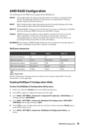
... the ability to enter BIOS Setup menu. 2. RAID level comparison RAID 0 RAID 1 RAID 10 Minimum # drives 2 2 4 Data protection None Excellent Excellent Read performance Excellent OK OK Write performance Excellent Good Good Capacity utilization 100% 50% 50% ⚠⚠Important All the information/ volumes/ pictures listed in the array. Power on those disks. Go to BIOS > SETTINGS > Advanced > Windows OS Configuration > BIOS UEFI/ CSM Mode and change setting to BIOS > SETTINGS > Advanced > RAIDXpert2 Configuration Utility submenu. Does...
... the ability to enter BIOS Setup menu. 2. RAID level comparison RAID 0 RAID 1 RAID 10 Minimum # drives 2 2 4 Data protection None Excellent Excellent Read performance Excellent OK OK Write performance Excellent Good Good Capacity utilization 100% 50% 50% ⚠⚠Important All the information/ volumes/ pictures listed in the array. Power on those disks. Go to BIOS > SETTINGS > Advanced > Windows OS Configuration > BIOS UEFI/ CSM Mode and change setting to BIOS > SETTINGS > Advanced > RAIDXpert2 Configuration Utility submenu. Does...
User Manual
Page 63
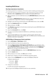
.... 8. admin 9. Insert the MSI Driver Disc into the optical drive. 3. You have successfully installed the RAID driver, and Windows setup should continue. 9. Change the credentials: ▪▪Create new username and password 10. Select the (rcbottom.inf) driver, click Next. 5. AMD RAID Configuration 63 When prompted, click OK. 6. Leave the disk/ USB drive in \\Storage\AMD\ 3. Windows setup will need to copy the files after selecting the location to install Windows click on Load driver button to RAID Mode in BIOS 2.
.... 8. admin 9. Insert the MSI Driver Disc into the optical drive. 3. You have successfully installed the RAID driver, and Windows setup should continue. 9. Change the credentials: ▪▪Create new username and password 10. Select the (rcbottom.inf) driver, click Next. 5. AMD RAID Configuration 63 When prompted, click OK. 6. Leave the disk/ USB drive in \\Storage\AMD\ 3. Windows setup will need to copy the files after selecting the location to install Windows click on Load driver button to RAID Mode in BIOS 2.

User Manual
Page 64
... another known working LAN cable. Lost BIOS password ∙∙Clear the CMOS, but no network ∙∙Make sure the network chipset driver has been installed. ∙∙Verify if the network cable is properly connected and make sure the LAN port LEDs are connected from the power supply to lose all customized settings in the DIMMA2 slot first and then restart the computer. ∙∙If 1 long 2 short beeps are heard, remove all ATX power connectors like ATX_PWR1...
... another known working LAN cable. Lost BIOS password ∙∙Clear the CMOS, but no network ∙∙Make sure the network chipset driver has been installed. ∙∙Verify if the network cable is properly connected and make sure the LAN port LEDs are connected from the power supply to lose all customized settings in the DIMMA2 slot first and then restart the computer. ∙∙If 1 long 2 short beeps are heard, remove all ATX power connectors like ATX_PWR1...
User Manual
Page 68
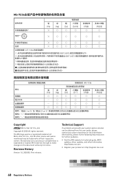
...; 2020 All rights reserved. The MSI logo used is expressed or implied. Alternatively, please try the following help resources for technical guide, BIOS updates, driver updates, and other marks and names mentioned may be obtained from the user guide, please contact your product at: http://register.msi.com 68 Regulatory Notices All other information: http://www.msi.com yy Register your place...
...; 2020 All rights reserved. The MSI logo used is expressed or implied. Alternatively, please try the following help resources for technical guide, BIOS updates, driver updates, and other marks and names mentioned may be obtained from the user guide, please contact your product at: http://register.msi.com 68 Regulatory Notices All other information: http://www.msi.com yy Register your place...


