User Guide
Page 2
..., technical guide, BIOS updates, driver updates, and other information: http://www.msi.com/service/download/ ◙ Contact our technical staff at: http://support.msi.com/ ii Alternatively, please try the following help resources for further guidance. ◙ Visit the MSI website for PCB 4.X Date 2011/06 Technical Support If a problem arises with your system and no guarantee is given as to make changes without...
..., technical guide, BIOS updates, driver updates, and other information: http://www.msi.com/service/download/ ◙ Contact our technical staff at: http://support.msi.com/ ii Alternatively, please try the following help resources for further guidance. ◙ Visit the MSI website for PCB 4.X Date 2011/06 Technical Support If a problem arises with your system and no guarantee is given as to make changes without...
User Guide
Page 8
... ii Technical Support ii Safety Instructions iii FCC-B Radio Frequency Interference Statement iv WEEE (Waste Electrical and Electronic Equipment) Statement v Chapter 1 Getting Started 1-1 Mainboard Specifications 1-2 Mainboard Layout 1-4 Packing Contents 1-5 Optional Accessories 1-5 Chapter 2 Hardware Setup 2-1 Quick Components Guide 2-2 Screw Holes 2-3 CPU (Central Processing Unit 2-4 Memory 2-7 Power Supply 2-9 Back Panel 2-10 Connectors 2-12 Jumpers 2-17 Slots 2-18 LED Status Indicators 2-19 Chapter 3 BIOS Setup 3-1 Entering Setup 3-2 The Menu Bar 3-4 Main Menu...
... ii Technical Support ii Safety Instructions iii FCC-B Radio Frequency Interference Statement iv WEEE (Waste Electrical and Electronic Equipment) Statement v Chapter 1 Getting Started 1-1 Mainboard Specifications 1-2 Mainboard Layout 1-4 Packing Contents 1-5 Optional Accessories 1-5 Chapter 2 Hardware Setup 2-1 Quick Components Guide 2-2 Screw Holes 2-3 CPU (Central Processing Unit 2-4 Memory 2-7 Power Supply 2-9 Back Panel 2-10 Connectors 2-12 Jumpers 2-17 Slots 2-18 LED Status Indicators 2-19 Chapter 3 BIOS Setup 3-1 Entering Setup 3-2 The Menu Bar 3-4 Main Menu...
User Guide
Page 12
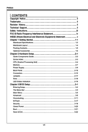
... on compatible components, please visit http://www.msi.com/service/test-report/) LAN ■ Supports PCIe Gb LAN (10/100/1000) by Realtek® RTL8111E Audio ■ HD audio codec integrated by Realtek® ALC892 ■ Flexible 8-channel audio with jack sensing SATA ■ 6 SATA 6Gb/s ports (SATA1~6) by AMD® SB950 ■ Supports hot plug & asynchronous notification USB 3.0 ■ 2 USB 3.0 ports (back panel) by NEC D720200 RAID ■ SATA1~6 support RAID 0/ 1/ 5/ 10 mode by AMD...
... on compatible components, please visit http://www.msi.com/service/test-report/) LAN ■ Supports PCIe Gb LAN (10/100/1000) by Realtek® RTL8111E Audio ■ HD audio codec integrated by Realtek® ALC892 ■ Flexible 8-channel audio with jack sensing SATA ■ 6 SATA 6Gb/s ports (SATA1~6) by AMD® SB950 ■ Supports hot plug & asynchronous notification USB 3.0 ■ 2 USB 3.0 ports (back panel) by NEC D720200 RAID ■ SATA1~6 support RAID 0/ 1/ 5/ 10 mode by AMD...

User Guide
Page 13
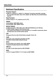
.../2 keyboard/ mouse port - 1 Clear CMOS button - 1 Coaxial S/PDIF-Out port - 1 Optical S/PDIF-Out port - 8 USB 2.0 ports - 2 USB 3.0 ports - 1 LAN port - 6 flexible audio ports ■ On-Board - 2 USB 2.0 connectors - 1 Serial port connector - 1 Chassis Intrusion connector - 1 S/PDIF-Out connector - 1 Front Panel Audio connector - 1 TPM Module connector Slots ■ 2 PCIe x16 slots - If two graphics cards are installed in both PCIe x16 slots, these two PCIe 2.0 x16 lanes will auto arrange from x16/ x0 to x8/ x8 ■ 4 PCIe x1 slots ■ 1 PCI slot, supports 3.3V/ 5V PCI bus Interface...
.../2 keyboard/ mouse port - 1 Clear CMOS button - 1 Coaxial S/PDIF-Out port - 1 Optical S/PDIF-Out port - 8 USB 2.0 ports - 2 USB 3.0 ports - 1 LAN port - 6 flexible audio ports ■ On-Board - 2 USB 2.0 connectors - 1 Serial port connector - 1 Chassis Intrusion connector - 1 S/PDIF-Out connector - 1 Front Panel Audio connector - 1 TPM Module connector Slots ■ 2 PCIe x16 slots - If two graphics cards are installed in both PCIe x16 slots, these two PCIe 2.0 x16 lanes will auto arrange from x16/ x0 to x8/ x8 ■ 4 PCIe x1 slots ■ 1 PCI slot, supports 3.3V/ 5V PCI bus Interface...
User Guide
Page 20
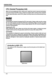
... to install the cooler to prevent overheating. Replacing the CPU While replacing the CPU, always turn off the ATX power supply or unplug the power supply's power cord from overheating. Gold arrow 2-4 Make sure that you apply an even layer of CPU. If you do not guarantee the damages or risks caused by inadequate operation or beyond product specifications is designed to support overclocking. Overclocking This mainboard is...
... to install the cooler to prevent overheating. Replacing the CPU While replacing the CPU, always turn off the ATX power supply or unplug the power supply's power cord from overheating. Gold arrow 2-4 Make sure that you apply an even layer of CPU. If you do not guarantee the damages or risks caused by inadequate operation or beyond product specifications is designed to support overclocking. Overclocking This mainboard is...

User Guide
Page 25
... the power supply is used to connect an ATX 24-pin power supply. Chapter 2 MS-7640 Power Supply ATX 24-pin Power Connector: JPWR1 This connector allows you like to use the 20-pin ATX power supply as you to provide +12V power. 1.G2.rG3o.urG4on.urdGonurdonudnd 5.+61.+721.V+821.V+21V2V Important Make sure that all the connectors are aligned. If you'd like . To connect the ATX 24-pin power supply, make sure the plug of the mainboard. 2-9 Then...
... the power supply is used to connect an ATX 24-pin power supply. Chapter 2 MS-7640 Power Supply ATX 24-pin Power Connector: JPWR1 This connector allows you like to use the 20-pin ATX power supply as you to provide +12V power. 1.G2.rG3o.urG4on.urdGonurdonudnd 5.+61.+721.V+821.V+21V2V Important Make sure that all the connectors are aligned. If you'd like . To connect the ATX 24-pin power supply, make sure the plug of the mainboard. 2-9 Then...

User Guide
Page 26
... USB 2.0 Port USB 3.0 Port Mic SS-Out ▶ Mouse/ Keyboard The standard PS/2® mouse/keyboard DIN connector is for a PS/2® mouse/keyboard. ▶ Clear CMOS Button There is a CMOS RAM on . Important • Make sure that has a power supply from external battery to external speakers through an optical fiber cable. ▶ USB 2.0 Port The USB (Universal Serial Bus) port is turned on board that you want to clear the system configuration, use the button to clear data. If you power...
... USB 2.0 Port USB 3.0 Port Mic SS-Out ▶ Mouse/ Keyboard The standard PS/2® mouse/keyboard DIN connector is for a PS/2® mouse/keyboard. ▶ Clear CMOS Button There is a CMOS RAM on . Important • Make sure that has a power supply from external battery to external speakers through an optical fiber cable. ▶ USB 2.0 Port The USB (Universal Serial Bus) port is turned on board that you want to clear the system configuration, use the button to clear data. If you power...

User Guide
Page 29
... can install Control Center utility that the red wire is Ground and should be connected to the +12V; If the mainboard has a System Hardware Monitor chipset on-board, you to connect the front panel audio and is compliant with +12V. When connecting the wire to the connectors, always note that will automatically control the fans speed according to the actual temperature. • Fan cooler set with speed sensor to the recommended CPU fans at processor...
... can install Control Center utility that the red wire is Ground and should be connected to the +12V; If the mainboard has a System Hardware Monitor chipset on-board, you to connect the front panel audio and is compliant with +12V. When connecting the wire to the connectors, always note that will automatically control the fans speed according to the actual temperature. • Fan cooler set with speed sensor to the recommended CPU fans at processor...

User Guide
Page 33
Avoid clearing the CMOS while the system is off. If you want to clear the system configuration, set the jumper to clear data. 1 JBAT1 1 Keep Data 1 Clear Data Important You can automatically boot OS every time it will damage the mainboard. 2-17 With the CMOS RAM, the system can clear CMOS by shorting 2-3 pin while the system is on . Chapter 2 MS-7640 Jumpers Clear CMOS Jumper: JBAT1 There is turned on ; Then return to keep the data of system configuration. it is a CMOS RAM onboard that has a power supply from an external battery to 1-2 pin position.
Avoid clearing the CMOS while the system is off. If you want to clear the system configuration, set the jumper to clear data. 1 JBAT1 1 Keep Data 1 Clear Data Important You can automatically boot OS every time it will damage the mainboard. 2-17 With the CMOS RAM, the system can clear CMOS by shorting 2-3 pin while the system is on . Chapter 2 MS-7640 Jumpers Clear CMOS Jumper: JBAT1 There is turned on ; Then return to keep the data of system configuration. it is a CMOS RAM onboard that has a power supply from an external battery to 1-2 pin position.

User Guide
Page 34
... the PCI bus pins as jumpers, switches or BIOS configuration. The PCI IRQ pins are hardware lines over which devices can send interrupt signals to configure any necessary hardware or software settings for the expansion card, such as follows: PCI Slot1 Order1 Order2 Order3 Order4 INT G# INT H# INT E# INT F# 2-18 PCIe x16 Slot PCIe x1 Slot PCI (Peripheral Component Interconnect) Slot The PCI slot supports LAN card, SCSI card, USB card, and other add-on cards that comply with PCI specifications. 32-bit PCI Slot...
... the PCI bus pins as jumpers, switches or BIOS configuration. The PCI IRQ pins are hardware lines over which devices can send interrupt signals to configure any necessary hardware or software settings for the expansion card, such as follows: PCI Slot1 Order1 Order2 Order3 Order4 INT G# INT H# INT E# INT F# 2-18 PCIe x16 Slot PCIe x1 Slot PCI (Peripheral Component Interconnect) Slot The PCI slot supports LAN card, SCSI card, USB card, and other add-on cards that comply with PCI specifications. 32-bit PCI Slot...

User Guide
Page 42
... enter the sub-menu. ▶ ACPI Standby State This item specifies the power saving modes for a longer time and thus improve the effective PCI bandwidth. For better PCI performance, you should set to enter the sub-menu. ▶ PCI Latency Timer This item controls how long each PCI device can conduct transactions for ACPI function. ▶ Power LED This item configures how the system uses power LED on the case to indicate the sleep...
... enter the sub-menu. ▶ ACPI Standby State This item specifies the power saving modes for a longer time and thus improve the effective PCI bandwidth. For better PCI performance, you should set to enter the sub-menu. ▶ PCI Latency Timer This item controls how long each PCI device can conduct transactions for ACPI function. ▶ Power LED This item configures how the system uses power LED on the case to indicate the sleep...

User Guide
Page 43
... ACPI methods. ▶ USB Configuration Press to enter the sub-menu. ▶ USB Devices: This item shows the type of installed USB device. ▶ USB Controller This item allows you to enable/ disable the USB controller. ▶ Legacy USB Support Set to [Enabled] if you need to use any USB 1.1/2.0 device in the operating system that is part of the onboard LAN. ▶ SATA Mode This item is used to specify a mode for SATA port. ▶ HD Audio Controller This item allows you want to use any USB device...
... ACPI methods. ▶ USB Configuration Press to enter the sub-menu. ▶ USB Devices: This item shows the type of installed USB device. ▶ USB Controller This item allows you to enable/ disable the USB controller. ▶ Legacy USB Support Set to [Enabled] if you need to use any USB 1.1/2.0 device in the operating system that is part of the onboard LAN. ▶ SATA Mode This item is used to specify a mode for SATA port. ▶ HD Audio Controller This item allows you want to use any USB device...

User Guide
Page 46
... to enter the sub-menu. ▶ Wake Up Event By Setting to [BIOS] activates the following fields, and use the following fields to set the wake up the system from S3 (Suspend to RAM) sleep state. ▶ Resume From S3 by PS/2 Mouse/ Keyboard These items determine whether the system will be awakened from the power saving modes through any event on PCI or PCIE device...
... to enter the sub-menu. ▶ Wake Up Event By Setting to [BIOS] activates the following fields, and use the following fields to set the wake up the system from S3 (Suspend to RAM) sleep state. ▶ Resume From S3 by PS/2 Mouse/ Keyboard These items determine whether the system will be awakened from the power saving modes through any event on PCI or PCIE device...

User Guide
Page 53
... selected BIOS file. ▶ Save BIOS to storage Please setup a specific folder in specific USB/ Storage drive to select particular BIOS file from the USB/ Storage (FAT/ 32 format only) drive. Note: it only supports FAT/ 32 file system drive. ▶ Select one file to Boot When the BIOS Boot function as sets to [Enabled], this item is selectable. M-Flash MS-7640 Chapter 3 ▶ BIOS Boot Function This allows you to enable/ disable the system to boot from the BIOS file inside USB drive...
... selected BIOS file. ▶ Save BIOS to storage Please setup a specific folder in specific USB/ Storage drive to select particular BIOS file from the USB/ Storage (FAT/ 32 format only) drive. Note: it only supports FAT/ 32 file system drive. ▶ Select one file to Boot When the BIOS Boot function as sets to [Enabled], this item is selectable. M-Flash MS-7640 Chapter 3 ▶ BIOS Boot Function This allows you to enable/ disable the system to boot from the BIOS file inside USB drive...

User Guide
Page 55
The setting of recording the chassis intrusion status and issuing a warning message if the chassis is selectable. Chapter 3 MS-7640 ▶ Make U-Key at When the "U-Key" as sets to [Enabled], this item is once opened. To clear the warning message, set the field to [Enabled] later. 3-19 This item allows you to specify the USB drive. ▶ Chassis Intrusion Configuration Press to enter the sub-menu. ▶ Chassis Intrusion This item enables or disables the feature of the field will automatically return to [Reset].
The setting of recording the chassis intrusion status and issuing a warning message if the chassis is selectable. Chapter 3 MS-7640 ▶ Make U-Key at When the "U-Key" as sets to [Enabled], this item is once opened. To clear the warning message, set the field to [Enabled] later. 3-19 This item allows you to specify the USB drive. ▶ Chassis Intrusion Configuration Press to enter the sub-menu. ▶ Chassis Intrusion This item enables or disables the feature of the field will automatically return to [Reset].

User Guide
Page 58
Save & Exit ▶ Discard Changes and Exit Use this item to abandon all changes and exit setup. ▶ Save Changes and Reboot Use this item to save changes and reset the system. ▶ Save Changes Use this item to save changes. ▶ Discard Changes Use this item to abandon all changes. ▶ Restore Defaults Use this item to load the optimized default values set by the BIOS vendor. == Boot Override == The installed storage devices will appear on this menu, you can select one of them be a boot device. ▶ Built-in EFI Shell Use this item to enter the EFI Shell.
Save & Exit ▶ Discard Changes and Exit Use this item to abandon all changes and exit setup. ▶ Save Changes and Reboot Use this item to save changes and reset the system. ▶ Save Changes Use this item to save changes. ▶ Discard Changes Use this item to abandon all changes. ▶ Restore Defaults Use this item to load the optimized default values set by the BIOS vendor. == Boot Override == The installed storage devices will appear on this menu, you can select one of them be a boot device. ▶ Built-in EFI Shell Use this item to enter the EFI Shell.

User Guide
Page 60
Insert the application DVD into the DVD-ROM drive. Click Next to enhance audio applications. Important The HD Audio Configuration software utility is under continuous update to install the Realtek High Definition Audio Driver. 6. A-2 Realtek Audio Installing the Realtek HD Audio Driver You need to install the HD audio driver for Windows® For Windows® XP, you must install Windows® XP Service Pack3 or later before you install the drivers in this section may be slightly different...
Insert the application DVD into the DVD-ROM drive. Click Next to enhance audio applications. Important The HD Audio Configuration software utility is under continuous update to install the Realtek High Definition Audio Driver. 6. A-2 Realtek Audio Installing the Realtek HD Audio Driver You need to install the HD audio driver for Windows® For Windows® XP, you must install Windows® XP Service Pack3 or later before you install the drivers in this section may be slightly different...

User Guide
Page 61
double click the icon It is also available to enable the audio driver by clicking the Realtek HD Audio Manager from the Control Panel. Software panel overview The following figure describes the function of the screen). Appendix A MS-7640 Software Configuration After installing the audio driver, the "Realtek HD Audio Manager" icon will pop up accordingly. Device Selection Application Enhancement Volume Adjustment Jack status panel A-3 You may double click the icon and the GUI will appear at the notification area (lower right of the Realtek HD Audio Manager panel.
double click the icon It is also available to enable the audio driver by clicking the Realtek HD Audio Manager from the Control Panel. Software panel overview The following figure describes the function of the screen). Appendix A MS-7640 Software Configuration After installing the audio driver, the "Realtek HD Audio Manager" icon will pop up accordingly. Device Selection Application Enhancement Volume Adjustment Jack status panel A-3 You may double click the icon and the GUI will appear at the notification area (lower right of the Realtek HD Audio Manager panel.

User Guide
Page 72
... instruction below to make a SATA RAID driver for yourself. • Insert the MSI DVD into the DVD-ROM drive. • Click the "Browse CD" on "Load Driver" button to copy the files from the Windows CD, and the Windows Setup program starts. 2. Leave the medium until the system reboots itself. Windows setup will need to load RAID drive. 5. AMD RAID Installing the RAID Driver (for 32-bit/ 64-bit version system and then press ENTER. 7. Press F6 and wait for the Windows Setup screen...
... instruction below to make a SATA RAID driver for yourself. • Insert the MSI DVD into the DVD-ROM drive. • Click the "Browse CD" on "Load Driver" button to copy the files from the Windows CD, and the Windows Setup program starts. 2. Leave the medium until the system reboots itself. Windows setup will need to load RAID drive. 5. AMD RAID Installing the RAID Driver (for 32-bit/ 64-bit version system and then press ENTER. 7. Press F6 and wait for the Windows Setup screen...
User Guide
Page 73
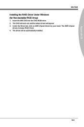
B-9 The AMD chipset drivers includes RAID Driver. 4. Appendix B MS-7640 Installing the RAID Driver Under Windows (for Non-bootable RAID Array) 1. The DVD will auto-run and the setup screen will be automatically installed. The driver will appear. 3. Under the Driver tab, click on AMD chipset drivers by your need. Insert the MSI DVD into the DVD-ROM drive. 2.
B-9 The AMD chipset drivers includes RAID Driver. 4. Appendix B MS-7640 Installing the RAID Driver Under Windows (for Non-bootable RAID Array) 1. The DVD will auto-run and the setup screen will be automatically installed. The driver will appear. 3. Under the Driver tab, click on AMD chipset drivers by your need. Insert the MSI DVD into the DVD-ROM drive. 2.


