User Guide
Page 2
... user's manual, please contact your system and no guarantee is given as to make changes without notice. Our products are under continual improvement and we reserve the right to the correctness of its contents. Revision History Revision V3.0 V3.1 V3.2 Revision History First release for FAQ, technical guide, BIOS updates, driver updates, and other information: http://www.msi.com/service/download...
... user's manual, please contact your system and no guarantee is given as to make changes without notice. Our products are under continual improvement and we reserve the right to the correctness of its contents. Revision History Revision V3.0 V3.1 V3.2 Revision History First release for FAQ, technical guide, BIOS updates, driver updates, and other information: http://www.msi.com/service/download...
User Guide
Page 8
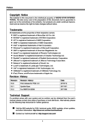
... ii Technical Support ii Safety Instructions iii FCC-B Radio Frequency Interference Statement iv WEEE (Waste Electrical and Electronic Equipment) Statement v Chapter 1 Getting Started 1-1 Mainboard Specifications 1-2 Mainboard Layout 1-4 Packing Contents 1-5 Optional Accessories 1-5 Chapter 2 Hardware Setup 2-1 Quick Components Guide 2-2 Screw Holes 2-3 CPU (Central Processing Unit 2-4 Memory 2-7 Power Supply 2-9 Back Panel 2-10 Connectors 2-12 Jumpers 2-17 Slots 2-18 LED Status Indicators 2-19 Chapter 3 BIOS Setup 3-1 Entering Setup 3-2 The Menu Bar 3-4 Main Menu...
... ii Technical Support ii Safety Instructions iii FCC-B Radio Frequency Interference Statement iv WEEE (Waste Electrical and Electronic Equipment) Statement v Chapter 1 Getting Started 1-1 Mainboard Specifications 1-2 Mainboard Layout 1-4 Packing Contents 1-5 Optional Accessories 1-5 Chapter 2 Hardware Setup 2-1 Quick Components Guide 2-2 Screw Holes 2-3 CPU (Central Processing Unit 2-4 Memory 2-7 Power Supply 2-9 Back Panel 2-10 Connectors 2-12 Jumpers 2-17 Slots 2-18 LED Status Indicators 2-19 Chapter 3 BIOS Setup 3-1 Entering Setup 3-2 The Menu Bar 3-4 Main Menu...
User Guide
Page 12
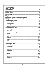
... on compatible components, please visit http://www.msi.com/service/test-report/) LAN ■ Supports PCIE Gb LAN (10/100/1000) by Realtek® RTL8111E Audio ■ HD audio codec integrated by Realtek® ALC892 ■ Flexible 8-channel audio with jack sensing SATA ■ 6 SATA 6Gb/s ports (SATA1~6) by AMD® SB950 ■ Supports hot plug & asynchronous notification USB 3.0 ■ 2 USB 3.0 ports (back panel) by NEC D720200 RAID ■ SATA1~6 support RAID 0/ 1/ 5/ 10 mode by AMD...
... on compatible components, please visit http://www.msi.com/service/test-report/) LAN ■ Supports PCIE Gb LAN (10/100/1000) by Realtek® RTL8111E Audio ■ HD audio codec integrated by Realtek® ALC892 ■ Flexible 8-channel audio with jack sensing SATA ■ 6 SATA 6Gb/s ports (SATA1~6) by AMD® SB950 ■ Supports hot plug & asynchronous notification USB 3.0 ■ 2 USB 3.0 ports (back panel) by NEC D720200 RAID ■ SATA1~6 support RAID 0/ 1/ 5/ 10 mode by AMD...

User Guide
Page 25
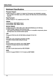
... connectors are connected to proper ATX power supplies to ensure stable operation of the power supply is used to provide power to connect an ATX 24-pin power supply. If you to the graphics card. To connect the ATX 24-pin power supply, make sure the plug of the mainboard. 2-9 Chapter 2 MS-7640 Power Supply ATX 24-pin Power Connector: JPWR1 This connector allows you 'd like . You may use the 20-pin ATX power supply as you like to use the 20-pin ATX power supply, please plug your power supply along with pin 1 & pin...
... connectors are connected to proper ATX power supplies to ensure stable operation of the power supply is used to provide power to connect an ATX 24-pin power supply. If you to the graphics card. To connect the ATX 24-pin power supply, make sure the plug of the mainboard. 2-9 Chapter 2 MS-7640 Power Supply ATX 24-pin Power Connector: JPWR1 This connector allows you 'd like . You may use the 20-pin ATX power supply as you like to use the 20-pin ATX power supply, please plug your power supply along with pin 1 & pin...

User Guide
Page 26
... this button to clear CMOS data in power off (G3) state, the system will boot automatically. ▶ Coaxial S/PDIF-Out This SPDIF (Sony & Philips Digital Interconnect Format) connector is provided for digital audio transmission to external speakers through an optical fiber cable. ▶ USB 2.0 Port The USB (Universal Serial Bus) port is a CMOS RAM on . Press the button to 480Mbit/s (Hi-Speed). 2-10 Hardware Setup Back Panel Mouse/ Keyboard Coaxial S/PDIF-Out Clear CMOS Button LAN Line...
... this button to clear CMOS data in power off (G3) state, the system will boot automatically. ▶ Coaxial S/PDIF-Out This SPDIF (Sony & Philips Digital Interconnect Format) connector is provided for digital audio transmission to external speakers through an optical fiber cable. ▶ USB 2.0 Port The USB (Universal Serial Bus) port is a CMOS RAM on . Press the button to 480Mbit/s (Hi-Speed). 2-10 Hardware Setup Back Panel Mouse/ Keyboard Coaxial S/PDIF-Out Clear CMOS Button LAN Line...

User Guide
Page 29
... actual CPU temperature. • Fan cooler set with speed sensor to take advantage of the CPU fan control. Front Panel Audio Connector: JAUD1 This connector allows you must use a specially designed fan with 3 or 4 pins power connector are both available for proper CPU cooling fan. • CPUFAN supports fan control. You can install Control Center utility that the red wire is compliant with +12V. If the mainboard has a System Hardware Monitor chipset on-board, you to the recommended CPU fans at processor's official...
... actual CPU temperature. • Fan cooler set with speed sensor to take advantage of the CPU fan control. Front Panel Audio Connector: JAUD1 This connector allows you must use a specially designed fan with 3 or 4 pins power connector are both available for proper CPU cooling fan. • CPUFAN supports fan control. You can install Control Center utility that the red wire is compliant with +12V. If the mainboard has a System Hardware Monitor chipset on-board, you to the recommended CPU fans at processor's official...

User Guide
Page 31
....U7BS.0G9B-.rN0o+ounPdin * The MB layout in this figure is provided for reference only. MS-7640 Front USB Connector: JUSB1, JUSB2 This connector, compliant with Intel® I/O Connectivity Design Guide, is a 16550A high speed communication port that sends/ receives 16 bytes FIFOs. USB 2.0 Bracket (optional) Serial Port Connector: JCOM1 This connector is ideal for connecting high-speed USB interface peripherals such as USB HDD, digital cameras, MP3 players, printers, modems...
....U7BS.0G9B-.rN0o+ounPdin * The MB layout in this figure is provided for reference only. MS-7640 Front USB Connector: JUSB1, JUSB2 This connector, compliant with Intel® I/O Connectivity Design Guide, is a 16550A high speed communication port that sends/ receives 16 bytes FIFOs. USB 2.0 Bracket (optional) Serial Port Connector: JCOM1 This connector is ideal for connecting high-speed USB interface peripherals such as USB HDD, digital cameras, MP3 players, printers, modems...

User Guide
Page 33
If you want to clear the system configuration, set the jumper to clear data. 1 JBAT1 1 Keep Data 1 Clear Data Important You can automatically boot OS every time it will damage the mainboard. 2-17 Avoid clearing the CMOS while the system is on . Then return to keep the data of system configuration. Chapter 2 MS-7640 Jumpers Clear CMOS Jumper: JBAT1 There is a CMOS RAM onboard that has a power supply from an external battery to 1-2 pin position. it is off. With the CMOS RAM, the system can clear CMOS by shorting 2-3 pin while the system is turned on ;
If you want to clear the system configuration, set the jumper to clear data. 1 JBAT1 1 Keep Data 1 Clear Data Important You can automatically boot OS every time it will damage the mainboard. 2-17 Avoid clearing the CMOS while the system is on . Then return to keep the data of system configuration. Chapter 2 MS-7640 Jumpers Clear CMOS Jumper: JBAT1 There is a CMOS RAM onboard that has a power supply from an external battery to 1-2 pin position. it is off. With the CMOS RAM, the system can clear CMOS by shorting 2-3 pin while the system is turned on ;

User Guide
Page 34
...) Slot The PCI slot supports LAN card, SCSI card, USB card, and other add-on cards that comply with PCI specifications. 32-bit PCI Slot Important When adding or removing expansion cards, make sure that you unplug the power supply first. The PCI IRQ pins are hardware lines over which devices can send interrupt signals to the PCI bus pins as jumpers, switches or BIOS configuration. Meanwhile, read the documentation for the expansion card to configure any necessary hardware or software settings for...
...) Slot The PCI slot supports LAN card, SCSI card, USB card, and other add-on cards that comply with PCI specifications. 32-bit PCI Slot Important When adding or removing expansion cards, make sure that you unplug the power supply first. The PCI IRQ pins are hardware lines over which devices can send interrupt signals to the PCI bus pins as jumpers, switches or BIOS configuration. Meanwhile, read the documentation for the expansion card to configure any necessary hardware or software settings for...

User Guide
Page 42
... enter the sub-menu. ▶ ACPI Standby State This item specifies the power saving modes for a longer time and thus improve the effective PCI bandwidth. For better PCI performance, you should set to enter the sub-menu. ▶ PCI Latency Timer This item controls how long each PCI device can conduct transactions for ACPI function. ▶ Power LED This item configures how the system uses power LED on the case to indicate the sleep...
... enter the sub-menu. ▶ ACPI Standby State This item specifies the power saving modes for a longer time and thus improve the effective PCI bandwidth. For better PCI performance, you should set to enter the sub-menu. ▶ PCI Latency Timer This item controls how long each PCI device can conduct transactions for ACPI function. ▶ Power LED This item configures how the system uses power LED on the case to indicate the sleep...

User Guide
Page 43
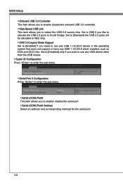
... it via the various ACPI methods. ▶ USB Configuration Press to enter the sub-menu. ▶ USB Devices: This item shows the type of installed USB device. ▶ USB Controller This item allows you to enable/ disable the USB controller. ▶ Legacy USB Support Set to [Enabled] if you to use any USB 1.1/2.0 device in the operating system that is part of the onboard LAN. ▶ SATA Mode This item is used to specify a mode for SATA port. ▶ HD Audio Controller This item allows you...
... it via the various ACPI methods. ▶ USB Configuration Press to enter the sub-menu. ▶ USB Devices: This item shows the type of installed USB device. ▶ USB Controller This item allows you to enable/ disable the USB controller. ▶ Legacy USB Support Set to [Enabled] if you to use any USB 1.1/2.0 device in the operating system that is part of the onboard LAN. ▶ SATA Mode This item is used to specify a mode for SATA port. ▶ HD Audio Controller This item allows you...
User Guide
Page 44
... USB device other than the USB mouse. ▶ Super IO Configuration Press to enter the sub-menu. ▶ Serial Port 0 Configuration Press to enter the sub-menu. ▶ Serial (COM) Port0 This item allows you want to use any USB 1.1/2.0/3.0 device in the operating system that does not support or have any USB 1.1/2.0/3.0 driver installed, such as DOS and SCO Unix. BIOS Setup ▶ Onboard USB 3.0 Controller This item allows you to enable/ disable the onboard USB 3.0 controller. ▶ High-Speed USB...
... USB device other than the USB mouse. ▶ Super IO Configuration Press to enter the sub-menu. ▶ Serial Port 0 Configuration Press to enter the sub-menu. ▶ Serial (COM) Port0 This item allows you want to use any USB 1.1/2.0/3.0 device in the operating system that does not support or have any USB 1.1/2.0/3.0 driver installed, such as DOS and SCO Unix. BIOS Setup ▶ Onboard USB 3.0 Controller This item allows you to enable/ disable the onboard USB 3.0 controller. ▶ High-Speed USB...

User Guide
Page 46
... PCI or PCI-E Device When set the wake up the system from S3 (Suspend to RAM) sleep state. ▶ Resume From S3 by USB Device The item allows the activity of the PS/2 mouse/ keyboard is detected. 3-10 BIOS Setup ▶ Wake Up Event Setup Press to enter the sub-menu. ▶ Wake Up Event By Setting to [BIOS] activates the following fields, and use the following fields to set to [Enabled...
... PCI or PCI-E Device When set the wake up the system from S3 (Suspend to RAM) sleep state. ▶ Resume From S3 by USB Device The item allows the activity of the PS/2 mouse/ keyboard is detected. 3-10 BIOS Setup ▶ Wake Up Event Setup Press to enter the sub-menu. ▶ Wake Up Event By Setting to [BIOS] activates the following fields, and use the following fields to set to [Enabled...
User Guide
Page 52
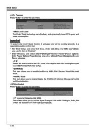
... "Enabled". • Enter Windows, and select [Start]->[Settings]->[Control Panel]->[Power Options]. BIOS Setup ▶ CPU Features Press to double confirm that: • Run BIOS Setup, and select Cell Menu. Setting to reduce the CPU power consumption while idle. Not all processors support Enhanced Halt state (C1E). ▶ SVM Mode This item allows you to enable/disable the AMD SVM (Secure Virtual Machine) Mode. ▶ IOMMU Mode This item allows you to enable/disable the IOMMU (I/O Memory Management Unit) for I/O virtualization...
... "Enabled". • Enter Windows, and select [Start]->[Settings]->[Control Panel]->[Power Options]. BIOS Setup ▶ CPU Features Press to double confirm that: • Run BIOS Setup, and select Cell Menu. Setting to reduce the CPU power consumption while idle. Not all processors support Enhanced Halt state (C1E). ▶ SVM Mode This item allows you to enable/disable the AMD SVM (Secure Virtual Machine) Mode. ▶ IOMMU Mode This item allows you to enable/disable the IOMMU (I/O Memory Management Unit) for I/O virtualization...

User Guide
Page 53
... select particular BIOS file from BIOS ROM chip data. This item allows to select particular BIOS file from the BIOS file inside USB drive (FAT/ 32 format only). ▶ Select one file to update BIOS This item allows you to enable/ disable the system to boot from the USB/ Storage (FAT/ 32 format only) drive. And the system will boot from selected BIOS file. ▶ Save BIOS to storage Please setup a specific folder in specific USB/ Storage drive to [Enabled], this item...
... select particular BIOS file from BIOS ROM chip data. This item allows to select particular BIOS file from the BIOS file inside USB drive (FAT/ 32 format only). ▶ Select one file to update BIOS This item allows you to enable/ disable the system to boot from the USB/ Storage (FAT/ 32 format only) drive. And the system will boot from selected BIOS file. ▶ Save BIOS to storage Please setup a specific folder in specific USB/ Storage drive to [Enabled], this item...

User Guide
Page 55
Chapter 3 MS-7640 ▶ Make U-Key at When the "U-Key" as sets to [Reset]. The setting of recording the chassis intrusion status and issuing a warning message if the chassis is selectable. This item allows you to specify the USB drive. ▶ Chassis Intrusion Configuration Press to enter the sub-menu. ▶ Chassis Intrusion This item enables or disables the feature of the field will automatically return to [Enabled] later. 3-19 To clear the warning message, set the field to [Enabled], this item is once opened.
Chapter 3 MS-7640 ▶ Make U-Key at When the "U-Key" as sets to [Reset]. The setting of recording the chassis intrusion status and issuing a warning message if the chassis is selectable. This item allows you to specify the USB drive. ▶ Chassis Intrusion Configuration Press to enter the sub-menu. ▶ Chassis Intrusion This item enables or disables the feature of the field will automatically return to [Enabled] later. 3-19 To clear the warning message, set the field to [Enabled], this item is once opened.

User Guide
Page 58
Save & Exit ▶ Discard Changes and Exit Use this item to abandon all changes and exit setup. ▶ Save Changes and Reboot Use this item to save changes and reset the system. ▶ Save Changes Use this item to save changes. ▶ Discard Changes Use this item to abandon all changes. ▶ Restore Defaults Use this item to load the optimized default values set by the BIOS vendor. == Boot Override == The installed storage devices will appear on this menu, you can select one of them be a boot device. ▶ Built-in EFI Shell Use this item to enter the EFI Shell.
Save & Exit ▶ Discard Changes and Exit Use this item to abandon all changes and exit setup. ▶ Save Changes and Reboot Use this item to save changes and reset the system. ▶ Save Changes Use this item to save changes. ▶ Discard Changes Use this item to abandon all changes. ▶ Restore Defaults Use this item to load the optimized default values set by the BIOS vendor. == Boot Override == The installed storage devices will appear on this menu, you can select one of them be a boot device. ▶ Built-in EFI Shell Use this item to enter the EFI Shell.

User Guide
Page 60
... Realtek High Definition Audio Driver. 6. Click Next to start installing the drivers. 5. Important The HD Audio Configuration software utility is under continuous update to 2-, 4-, 6-, 8- Hence, the program screens shown here in different operating systems. 1. Insert the application DVD into the DVD-ROM drive. cally appear. 2. The following illustrations are based on -screen instructions to install the drivers for different operating systems. Installation for Windows® For Windows® XP, you must install Windows® XP Service...
... Realtek High Definition Audio Driver. 6. Click Next to start installing the drivers. 5. Important The HD Audio Configuration software utility is under continuous update to 2-, 4-, 6-, 8- Hence, the program screens shown here in different operating systems. 1. Insert the application DVD into the DVD-ROM drive. cally appear. 2. The following illustrations are based on -screen instructions to install the drivers for different operating systems. Installation for Windows® For Windows® XP, you must install Windows® XP Service...
User Guide
Page 72
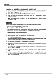
.../ Windows 7, you have successfully installed the RAID driver, and Windows setup should be shown a list of available RAID controller(s). 6. Press F6 and wait for the Windows Setup screen to OS.) • The driver disk for yourself. • Insert the MSI DVD into the DVD-ROM drive. • Click the "Browse CD" on "Load Driver" button to copy the files from the Windows CD, and the Windows Setup program starts. 2. AMD RAID Installing the RAID Driver (for 32-bit/ 64-bit version system and then press ENTER...
.../ Windows 7, you have successfully installed the RAID driver, and Windows setup should be shown a list of available RAID controller(s). 6. Press F6 and wait for the Windows Setup screen to OS.) • The driver disk for yourself. • Insert the MSI DVD into the DVD-ROM drive. • Click the "Browse CD" on "Load Driver" button to copy the files from the Windows CD, and the Windows Setup program starts. 2. AMD RAID Installing the RAID Driver (for 32-bit/ 64-bit version system and then press ENTER...
User Guide
Page 73
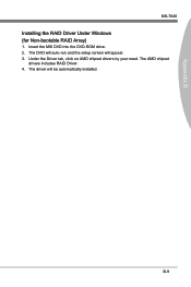
Under the Driver tab, click on AMD chipset drivers by your need. The driver will appear. 3. B-9 Insert the MSI DVD into the DVD-ROM drive. 2. The AMD chipset drivers includes RAID Driver. 4. Appendix B MS-7640 Installing the RAID Driver Under Windows (for Non-bootable RAID Array) 1. The DVD will auto-run and the setup screen will be automatically installed.
Under the Driver tab, click on AMD chipset drivers by your need. The driver will appear. 3. B-9 Insert the MSI DVD into the DVD-ROM drive. 2. The AMD chipset drivers includes RAID Driver. 4. Appendix B MS-7640 Installing the RAID Driver Under Windows (for Non-bootable RAID Array) 1. The DVD will auto-run and the setup screen will be automatically installed.

