User Guide
Page 8
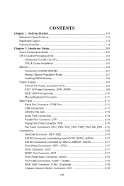
... & Cooler Installation 2-5 Memory ...2-6 Introduction to DDRII SDRAM 2-7 Memory Module Population Rules 2-7 Installing DDRII Modules 2-8 Power Supply ...2-8 ATX 24-Pin Power Connector: ATX 2-9 ATX 12V Power Connector: JPW/ JPWR 2-9 IEEE 1394 Port (optional 2-10 Mouse/Keyboard Connector 2-11 Back Panel ...2-11 Serial Port... Connector: COM Port 2-11 USB Connectors 2-11 LAN (RJ-45) Jack 2-13 Audio Port Connectors 2-13 Parallel...
... & Cooler Installation 2-5 Memory ...2-6 Introduction to DDRII SDRAM 2-7 Memory Module Population Rules 2-7 Installing DDRII Modules 2-8 Power Supply ...2-8 ATX 24-Pin Power Connector: ATX 2-9 ATX 12V Power Connector: JPW/ JPWR 2-9 IEEE 1394 Port (optional 2-10 Mouse/Keyboard Connector 2-11 Back Panel ...2-11 Serial Port... Connector: COM Port 2-11 USB Connectors 2-11 LAN (RJ-45) Jack 2-13 Audio Port Connectors 2-13 Parallel...
User Guide
Page 14
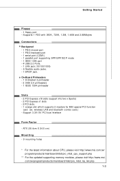
...- 1 serial port (COM1) - 1 parallel port supporting SPP/EPP/ECP mode - 1 IEEE 1394 port - 4 USB 2.0 Ports. - 1 LAN jack (10/100/1000) - 6 flexible audio jacks. - 1 SPDIF jack. ATX (30.4cm X 24.5 cm) Mounting - 9 mounting holes * For the latest information about CPU, please visit http...://www.msi.com.tw/ program/products/mainboard/mbd/pro_mbd_cpu_support.php ** For the updated supporting memory modules, please visit http://www.msi. On-Board Pinheaders - 1 D-Bracket 2 pinheader - 2 USB 2.0...
...- 1 serial port (COM1) - 1 parallel port supporting SPP/EPP/ECP mode - 1 IEEE 1394 port - 4 USB 2.0 Ports. - 1 LAN jack (10/100/1000) - 6 flexible audio jacks. - 1 SPDIF jack. ATX (30.4cm X 24.5 cm) Mounting - 9 mounting holes * For the latest information about CPU, please visit http...://www.msi.com.tw/ program/products/mainboard/mbd/pro_mbd_cpu_support.php ** For the updated supporting memory modules, please visit http://www.msi. On-Board Pinheaders - 1 D-Bracket 2 pinheader - 2 USB 2.0...
User Guide
Page 15
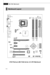
... COM A 1394 Port SPDIF SYSFAN1 J CI1 W inbo nd W83627DHG ATX1 USB ports T: LAN jack B: USB ports T:Line-I n M:Line-O ut B :M i c T:RS -Out M:CS- Out B:SS-O ut CP UFA N1 JPW NB_FAN1 Int e l 975X JPWR JCD1 ALC882M PCI_E1 PCI_E2 PEG1 JAUD1 JSP1 PCI2 VIA VT6308P PCI3 PEG2 ...J1394_2 B ATT + BIOS Intel ICH7DH SATA4 SATA3 SATA2 SATA1 Jmi cro n JMB361 JLPC1 SATA5 SW1 JUSB2 JUSB1 JFP1 JFP2 JLED1 975X Platinum (MS-7246) Series v2.X ATX Mainboard 1-4
... COM A 1394 Port SPDIF SYSFAN1 J CI1 W inbo nd W83627DHG ATX1 USB ports T: LAN jack B: USB ports T:Line-I n M:Line-O ut B :M i c T:RS -Out M:CS- Out B:SS-O ut CP UFA N1 JPW NB_FAN1 Int e l 975X JPWR JCD1 ALC882M PCI_E1 PCI_E2 PEG1 JAUD1 JSP1 PCI2 VIA VT6308P PCI3 PEG2 ...J1394_2 B ATT + BIOS Intel ICH7DH SATA4 SATA3 SATA2 SATA1 Jmi cro n JMB361 JLPC1 SATA5 SW1 JUSB2 JUSB1 JFP1 JFP2 JLED1 975X Platinum (MS-7246) Series v2.X ATX Mainboard 1-4

User Guide
Page 26
.... MS-7246 Mainboard Back Panel The back panel provides the following connectors: Mouse Parallel LAN L-In RS-Out Keyboard COM Port IEEE1394 SPDIF (optional) Out USB Ports L-Out CS-Out Mic SS-Out Mouse/Keyboard Connector The mainboard provides a standard PS/2® mouse/keyboard mini DIN connector for 1394 devices. 2-10...
.... MS-7246 Mainboard Back Panel The back panel provides the following connectors: Mouse Parallel LAN L-In RS-Out Keyboard COM Port IEEE1394 SPDIF (optional) Out USB Ports L-Out CS-Out Mic SS-Out Mouse/Keyboard Connector The mainboard provides a standard PS/2® mouse/keyboard mini DIN connector for 1394 devices. 2-10...

User Guide
Page 27
...Data Serial Out or Transmit Data Data Terminal Ready) Ground Data Set Ready Request To Send Clear To Send Ring Indicate USB Connectors The mainboard provides an OHCI (Open Host Controller Interface) Universal Serial Bus root for attaching... USB devices such as keyboard, mouse or other USBcompatible devices. You can plug the USB device directly into the connector. 1 23 4 5 67 8 USB Ports USB Port Description PIN SIGNAL 1 VCC 2 -Data 0 3 +Data0 4 GND 5 VCC 6 -Data 1 7 +Data 1...
...Data Serial Out or Transmit Data Data Terminal Ready) Ground Data Set Ready Request To Send Clear To Send Ring Indicate USB Connectors The mainboard provides an OHCI (Open Host Controller Interface) Universal Serial Bus root for attaching... USB devices such as keyboard, mouse or other USBcompatible devices. You can plug the USB device directly into the connector. 1 23 4 5 67 8 USB Ports USB Port Description PIN SIGNAL 1 VCC 2 -Data 0 3 +Data0 4 GND 5 VCC 6 -Data 1 7 +Data 1...
User Guide
Page 30
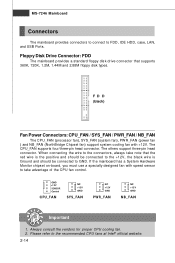
... SENSOR Control CPU_FAN NC +12V GND SYS_FAN NC +12V GND PWR_FAN NC +12V GND NB_FAN Important 1. Please refer to FDD, IDE HDD, case, LAN, and USB Ports. MS-7246 Mainboard Connectors The mainboard provides connectors to connect to the recommended CPU fans at Intel® official website. 2-14 Always consult the...
... SENSOR Control CPU_FAN NC +12V GND SYS_FAN NC +12V GND PWR_FAN NC +12V GND NB_FAN Important 1. Please refer to FDD, IDE HDD, case, LAN, and USB Ports. MS-7246 Mainboard Connectors The mainboard provides connectors to connect to the recommended CPU fans at Intel® official website. 2-14 Always consult the...

User Guide
Page 34
... Panel Audio Connector: JAUD1 The JAUD1 front panel audio connector allows you to connect to the analog header. Pin Definition 2 10 1 9 JUSB1 / JUSB2 (USB 2.0/standard spec) PIN SIGNAL 1 VCC 3 USB0- 5 USB0+ 7 GND 9 Key PIN SIGNAL 2 VCC 4 USB1- 6 USB1+ 8 GND 10 USBOC... Definition Audio dongle is connected. 5 PORT 2R Analog Port 2 - signals BIOS that the pins of 480Mbps, which is 40 times faster than USB 1.1, and is compliant with Intel® Front Panel I/O Connectivity Design Guide. 2 10 JAUD1 1 9 Pin Definition PIN SIGNAL DESCRIPTION 1 PORT...
... Panel Audio Connector: JAUD1 The JAUD1 front panel audio connector allows you to connect to the analog header. Pin Definition 2 10 1 9 JUSB1 / JUSB2 (USB 2.0/standard spec) PIN SIGNAL 1 VCC 3 USB0- 5 USB0+ 7 GND 9 Key PIN SIGNAL 2 VCC 4 USB1- 6 USB1+ 8 GND 10 USBOC... Definition Audio dongle is connected. 5 PORT 2R Analog Port 2 - signals BIOS that the pins of 480Mbps, which is 40 times faster than USB 1.1, and is compliant with Intel® Front Panel I/O Connectivity Design Guide. 2 10 JAUD1 1 9 Pin Definition PIN SIGNAL DESCRIPTION 1 PORT...

User Guide
Page 36
... to D-Bracket™ 2. This special feature is very useful for you to connect to JUSB1 or JUSB2 (the USB pinheader in YELLOW color) LEDs D-Bracket™ 2 is a USB Bracket that fail the system, such as VGA, RAM or other failures. These users can debug all problems that supports... both USB 1.1 & 2.0 specification. The 4 LEDs can use graphic signal display to detect if there are any problems or failures. D-Bracket™ 2 is an external USB bracket integrating four Diagnostic LEDs, which use the feature to help...
... to D-Bracket™ 2. This special feature is very useful for you to connect to JUSB1 or JUSB2 (the USB pinheader in YELLOW color) LEDs D-Bracket™ 2 is a USB Bracket that fail the system, such as VGA, RAM or other failures. These users can debug all problems that supports... both USB 1.1 & 2.0 specification. The 4 LEDs can use graphic signal display to detect if there are any problems or failures. D-Bracket™ 2 is an external USB bracket integrating four Diagnostic LEDs, which use the feature to help...

User Guide
Page 55
... device in the operating system. Setting options: [Enabled], [Disabled]. Setting options: [Enabled], [Disabled]. USB Keyboard Support Select [Enabled] if you have USB peripherals. Setting options: [Enabled], [Disabled]. Onboard VIA6306 (IEEE1394) This setting controls the onboard VIA 1394... controller. Selecting Enabled for Azalia, Disabled for AC'97. Setting options: [Enabled], [Disabled]. USB 2.0 Controller Select [Enabled] if your system contains a Universal Serial Bus (USB) controller and you need to support Azalia Audio or AC97 Audio. Setting options: [IDE], [...
... device in the operating system. Setting options: [Enabled], [Disabled]. Setting options: [Enabled], [Disabled]. USB Keyboard Support Select [Enabled] if you have USB peripherals. Setting options: [Enabled], [Disabled]. Onboard VIA6306 (IEEE1394) This setting controls the onboard VIA 1394... controller. Selecting Enabled for Azalia, Disabled for AC'97. Setting options: [Enabled], [Disabled]. USB 2.0 Controller Select [Enabled] if your system contains a Universal Serial Bus (USB) controller and you need to support Azalia Audio or AC97 Audio. Setting options: [IDE], [...

User Guide
Page 60
... to wake up the system from the S3, S4, and S5 power off state. Setting options: [Disabled], [Enabled]. 3-17 Resume by USB The item allows the activity of the USB device to RAM) sleep state. BIOS Setup Suspend Time Out (Minute) If system activity is not detected for more than four seconds...
... to wake up the system from the S3, S4, and S5 power off state. Setting options: [Disabled], [Enabled]. 3-17 Resume by USB The item allows the activity of the USB device to RAM) sleep state. BIOS Setup Suspend Time Out (Minute) If system activity is not detected for more than four seconds...


