User Guide
Page 8
... v Chapter 1 Getting Started 1-1 Mainboard Specifications 1-2 Mainboard Layout 1-4 Packing Checklist 1-4 MSI Special Feature 1-6 Core Center 1-6 Chapter 2 Getting Started 1-1 Quick Components Guide 2-2 CPU (Central Processing Unit 2-3 Introduction to LGA 775 CPU 2-3 CPU & Cooler Installation 2-4 Memory ...2-7 Installing DDRII Modules 2-8 Power Supply ...2-9 ATX 24-Pin Power Connector: ATX1 2-9 ATX 12V Power Connector: JPW 1 2-9 Back Panel ...2-10 Connectors ...2-12...
... v Chapter 1 Getting Started 1-1 Mainboard Specifications 1-2 Mainboard Layout 1-4 Packing Checklist 1-4 MSI Special Feature 1-6 Core Center 1-6 Chapter 2 Getting Started 1-1 Quick Components Guide 2-2 CPU (Central Processing Unit 2-3 Introduction to LGA 775 CPU 2-3 CPU & Cooler Installation 2-4 Memory ...2-7 Installing DDRII Modules 2-8 Power Supply ...2-9 ATX 24-Pin Power Connector: ATX1 2-9 ATX 12V Power Connector: JPW 1 2-9 Back Panel ...2-10 Connectors ...2-12...
User Guide
Page 11
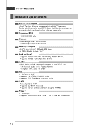
..., please visit http://www.msi.com.tw/ program/products/mainboard/mbd/pro_mbd_cpu_support.php Supported FSB - 1066/ 800/ 533 MHz Chipset - Compliant with 360K, 720K, 1.2M, 1.44M and 2.88Mbytes 1-2 Supports PIO, Bus Master operation mode SATA - SATA II ports by 8100C Audio - South Bridge: Intel® ICH7 chipset Memory Support - Supports 1 FDD with...
..., please visit http://www.msi.com.tw/ program/products/mainboard/mbd/pro_mbd_cpu_support.php Supported FSB - 1066/ 800/ 533 MHz Chipset - Compliant with 360K, 720K, 1.2M, 1.44M and 2.88Mbytes 1-2 Supports PIO, Bus Master operation mode SATA - SATA II ports by 8100C Audio - South Bridge: Intel® ICH7 chipset Memory Support - Supports 1 FDD with...
User Guide
Page 16
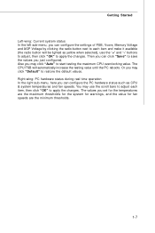
... "OK" to apply the changes. Getting Started Left-wing: Current system status In the left sub-menu, you can configure the settings of FSB, Vcore, Memory Voltage and AGP Voltage by clicking the radio button next to each item, then click "OK" to apply the changes. Also you can configure the...
... "OK" to apply the changes. Getting Started Left-wing: Current system status In the left sub-menu, you can configure the settings of FSB, Vcore, Memory Voltage and AGP Voltage by clicking the radio button next to each item, then click "OK" to apply the changes. Also you can configure the...
User Guide
Page 23
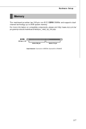
Channel B in GREEN; DDRII 240-pin, 1.8V 64x2=128 pin 56x2=112 pin Dual-Channel: Channel A in ORANGE 2-7 For more information on compatible components, please visit http://www.msi.com.tw/ p ro gr a m/ pr od u c t s / m ainb o ar d/ mb d /p ro _ mb d_ t rp _lis t .p hp . Hardware Setup Memory The mainboard provides two 240-pin non-ECC DDRII DIMMs and supports dualchannel technology up to 2GB system memory.
Channel B in GREEN; DDRII 240-pin, 1.8V 64x2=128 pin 56x2=112 pin Dual-Channel: Channel A in ORANGE 2-7 For more information on compatible components, please visit http://www.msi.com.tw/ p ro gr a m/ pr od u c t s / m ainb o ar d/ mb d /p ro _ mb d_ t rp _lis t .p hp . Hardware Setup Memory The mainboard provides two 240-pin non-ECC DDRII DIMMs and supports dualchannel technology up to 2GB system memory.
User Guide
Page 24
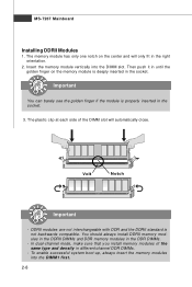
...in different channel DDR DIMMs. - In dual-channel mode, make sure that you install memory modules of the DIMM slot will only fit in the socket. The memory module has only one notch on the memory module is deeply inserted in the right orientation. 2. Important You can barely see the ...golden finger if the module is not backwards compatible. You should always install DDRII memory modules in the DDRII DIMMs and DDR memory modules in the socket. 3. DDRII modules are not interchangeable with DDR and the DDRII standard is properly inserted in the ...
...in different channel DDR DIMMs. - In dual-channel mode, make sure that you install memory modules of the DIMM slot will only fit in the socket. The memory module has only one notch on the memory module is deeply inserted in the right orientation. 2. Important You can barely see the ...golden finger if the module is not backwards compatible. You should always install DDRII memory modules in the DDRII DIMMs and DDR memory modules in the socket. 3. DDRII modules are not interchangeable with DDR and the DDRII standard is properly inserted in the ...
User Guide
Page 39
Upon boot-up, the 1st line appearing after the memory count is usually in this BIOS was released. 3-2 V3.0 refers to the BIOS version. 082506 refers to enter Setup. Press DEL to enter SETUP If ...
Upon boot-up, the 1st line appearing after the memory count is usually in this BIOS was released. 3-2 V3.0 refers to the BIOS version. 082506 refers to enter Setup. Press DEL to enter SETUP If ...
User Guide
Page 44
... devices that monitors your system (read or write more sector at boot. DM A M ode This item allows you to enable or disable the DMA (Direct Memory Access) mode. This allows you set the type of your disk status to predict hard disk failure. PIO Mode The PIO (Programmed Input/Output) Mode...-Monitoring Analysis & Reporting Technology) capability for the hard disks. S.M.A.R.T is a utility that the onboard IDE interface supports. It shows the CPU information, BIOS version and memory status of floppy drives installed.
... devices that monitors your system (read or write more sector at boot. DM A M ode This item allows you to enable or disable the DMA (Direct Memory Access) mode. This allows you set the type of your disk status to predict hard disk failure. PIO Mode The PIO (Programmed Input/Output) Mode...-Monitoring Analysis & Reporting Technology) capability for the hard disks. S.M.A.R.T is a utility that the onboard IDE interface supports. It shows the CPU information, BIOS version and memory status of floppy drives installed.
User Guide
Page 45
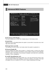
... SpeedStep technology allows you to show the company logo on the bootup screen. Intel(R) SpeedStep(tm) tech. W hen a malicious worm attempts to insert code in memory by where application code can execute and where it will appear after you to set the Num Lock status when the system is running on...
... SpeedStep technology allows you to show the company logo on the bootup screen. Intel(R) SpeedStep(tm) tech. W hen a malicious worm attempts to insert code in memory by where application code can execute and where it will appear after you to set the Num Lock status when the system is running on...
User Guide
Page 47
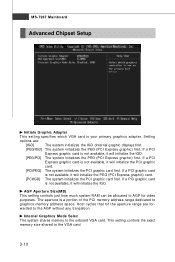
... it will initialize the IGD. [PEG/PCI] The system initializes the PEG (PCI Express graphic) first. Internal Graphics Mode Selec The system shares memory to the VGA card. 3-10 Host cycles that hit the aperture range are : [IGD] The system initializes the IGD (internal graphic display) first.... [PEG/IGD] The system initializes the PEG (PCI Express graphic) first. This setting controls the exact memory size shared to the onboard VGA card. If a PCI Express graphic card is your primary graphics adapter. Setting options are forwarded to the AGP...
... it will initialize the IGD. [PEG/PCI] The system initializes the PEG (PCI Express graphic) first. Internal Graphics Mode Selec The system shares memory to the VGA card. 3-10 Host cycles that hit the aperture range are : [IGD] The system initializes the IGD (internal graphic display) first.... [PEG/IGD] The system initializes the PEG (PCI Express graphic) first. This setting controls the exact memory size shared to the onboard VGA card. If a PCI Express graphic card is your primary graphics adapter. Setting options are forwarded to the AGP...
User Guide
Page 51
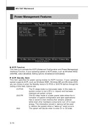
... the ACPI (Advanced Configuration and Power Management Interface) Function. Options are: S1/POS S3/STR Auto The S1 sleep mode is saved to main memory that remains powered while most other hardware components turn off to enter S1 or S3 state. 3-14 Setting options: [Enabled] and [Disabled]. If...operating system is ACPI-aware, such as W indows 98SE, W indows ME and W indows 2000, you can choose to enter the Standby mode in memory will decide when to save energy. MS-7267 Mainboard Power Management Features ACPI Function This item is to restore the system when a "wake up" event...
... the ACPI (Advanced Configuration and Power Management Interface) Function. Options are: S1/POS S3/STR Auto The S1 sleep mode is saved to main memory that remains powered while most other hardware components turn off to enter S1 or S3 state. 3-14 Setting options: [Enabled] and [Disabled]. If...operating system is ACPI-aware, such as W indows 98SE, W indows ME and W indows 2000, you can choose to enter the Standby mode in memory will decide when to save energy. MS-7267 Mainboard Power Management Features ACPI Function This item is to restore the system when a "wake up" event...
User Guide
Page 55
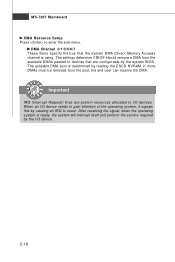
... itself and perform the service required by reading the ESCD NVRAM. MS-7267 Mainboard DM A Resource Setup Press to devices that the system DMA (Direct Memory Access) channel is using. Important IRQ (Interrupt Request) lines are configurable by causing an IRQ to I /O device needs to gain attention of the operating system...
... itself and perform the service required by reading the ESCD NVRAM. MS-7267 Mainboard DM A Resource Setup Press to devices that the system DMA (Direct Memory Access) channel is using. Important IRQ (Interrupt Request) lines are configurable by causing an IRQ to I /O device needs to gain attention of the operating system...
User Guide
Page 57
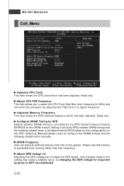
...can increase the DDR speed. Adjust DDR Voltage (V) Adjusting the DDR voltage can place an artificial memory clock limit on the system. Read only. Adjusted Memory Frequency This item shows the DDR memory frequency which had been adjusted. Selecting [Manual] allows users to a higher frequency. Any changes... made to be determined by the SPD (Serial Presence Detect) EEPROM on the SPD. Read only.. Please note that memory is prevented from running faster than this setting may cause a stability issue, so changing the DDR voltage for long-term purpose is ...
...can increase the DDR speed. Adjust DDR Voltage (V) Adjusting the DDR voltage can place an artificial memory clock limit on the system. Read only. Adjusted Memory Frequency This item shows the DDR memory frequency which had been adjusted. Selecting [Manual] allows users to a higher frequency. Any changes... made to be determined by the SPD (Serial Presence Detect) EEPROM on the SPD. Read only.. Please note that memory is prevented from running faster than this setting may cause a stability issue, so changing the DDR voltage for long-term purpose is ...

User Guide
Page 60
This prevents an unauthorized person from CMOS memory. Once the password is disabled, the system will be prompted to confirm the password. Retype the password and press . W hen a password has been set password, ...
This prevents an unauthorized person from CMOS memory. Once the password is disabled, the system will be prompted to confirm the password. Retype the password and press . W hen a password has been set password, ...


