
User Guide
Page 2
..., DualNet, and nForce are under continual improvement and we reserve the right to the correctness of its contents. Visit the MSI website for PCB 3.X Date August 2006 Technical Support If a problem arises with your system and no guarantee is a registered...of International Business Machines Corporation. Trademarks All trademarks are registered trademarks of their respective owners. Award® is the intellectual property of Intel Corporation. Netware® is a registered trademark of AMD Corporation. AMD, Athlon™, Athlon™ XP, Thoroughbred™, and ...
..., DualNet, and nForce are under continual improvement and we reserve the right to the correctness of its contents. Visit the MSI website for PCB 3.X Date August 2006 Technical Support If a problem arises with your system and no guarantee is a registered...of International Business Machines Corporation. Trademarks All trademarks are registered trademarks of their respective owners. Award® is the intellectual property of Intel Corporation. Netware® is a registered trademark of AMD Corporation. AMD, Athlon™, Athlon™ XP, Thoroughbred™, and ...
User Guide
Page 10
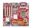
Getting Started Chapter 1 Getting Started Thank you for optimal system efficiency. Designed to fit the advanced Intel® Pentium 4 Series LGA775 processor, the 945GM3 Series mainboard delivers a high performance and professional desktop platform solution. 1-1 The 945G M 3 Series mainboard is based on Intel® 945G and Intel® ICH7 chipset for choosing the 945GM3 Series (MS-7267) v3.x Mic ro-AT X mainboard.
Getting Started Chapter 1 Getting Started Thank you for optimal system efficiency. Designed to fit the advanced Intel® Pentium 4 Series LGA775 processor, the 945GM3 Series mainboard delivers a high performance and professional desktop platform solution. 1-1 The 945G M 3 Series mainboard is based on Intel® 945G and Intel® ICH7 chipset for choosing the 945GM3 Series (MS-7267) v3.x Mic ro-AT X mainboard.
User Guide
Page 11
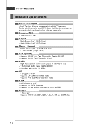
For the latest information about CPU, please visit http://www.msi.com.tw/ program/products/mainboard/mbd/pro_mbd_cpu_support.php Supported FSB - 1066/ 800/ 533 MHz Chipset - High Definition link controller integrated in the LGA775 package. Supports ... 300MB/s Floppy - 1 floppy port - Supports 10/100/1000 Fast Ethermet by ICH7 - SATA II ports by Realtek 8110SC - Supports four SATA II devices - North Bridge: Intel® 945G chipset - Supports 1 FDD with Azalia 1.0 SPEC IDE - 1 IDE port by 8100C Audio - DDRII 400/ 533/ 667 SDRAM (2GB Max) - 2 DDRII DIMMs (240pin / 1.8V...
For the latest information about CPU, please visit http://www.msi.com.tw/ program/products/mainboard/mbd/pro_mbd_cpu_support.php Supported FSB - 1066/ 800/ 533 MHz Chipset - High Definition link controller integrated in the LGA775 package. Supports ... 300MB/s Floppy - 1 floppy port - Supports 10/100/1000 Fast Ethermet by ICH7 - SATA II ports by Realtek 8110SC - Supports four SATA II devices - North Bridge: Intel® 945G chipset - Supports 1 FDD with Azalia 1.0 SPEC IDE - 1 IDE port by 8100C Audio - DDRII 400/ 533/ 667 SDRAM (2GB Max) - 2 DDRII DIMMs (240pin / 1.8V...
User Guide
Page 13
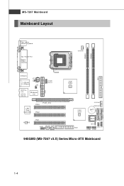
MS-7267 Mainboard Mainboard Layout Top : mouse Bottom: keyboard Top : Parallel Port Bottom: COM A VGA Port CP UFA N1 DIMM1 DIMM2 USB ports JCI1 T: LAN jack B: USB ports JPW1 JIR1 T:L i ne -I /O ATX1 JCOM2 ( op t io n al ) LAN Chip (optional) PCI3 PCIE_X16 PCI2 ALC883 PCI1 JAUD1 CD_IN1 JSPD1 ( Op tio na l) Intel 945G FDD1 SYS FA N1 PWRFAN1 BATT + BIOS JB AT1 JFP2 JFP1 JUSB2 JUSB1 IDE 1 945GM3 (MS-7267 v3.X) Series Micro-ATX Mainboard S ATA 4 SATA1 SATA2 SATA3 1-4 Ou t M:CS-Out B:S S-Out Winbond I n M:Li ne-Out B:Mic T:R S-
MS-7267 Mainboard Mainboard Layout Top : mouse Bottom: keyboard Top : Parallel Port Bottom: COM A VGA Port CP UFA N1 DIMM1 DIMM2 USB ports JCI1 T: LAN jack B: USB ports JPW1 JIR1 T:L i ne -I /O ATX1 JCOM2 ( op t io n al ) LAN Chip (optional) PCI3 PCIE_X16 PCI2 ALC883 PCI1 JAUD1 CD_IN1 JSPD1 ( Op tio na l) Intel 945G FDD1 SYS FA N1 PWRFAN1 BATT + BIOS JB AT1 JFP2 JFP1 JUSB2 JUSB1 IDE 1 945GM3 (MS-7267 v3.X) Series Micro-ATX Mainboard S ATA 4 SATA1 SATA2 SATA3 1-4 Ou t M:CS-Out B:S S-Out Winbond I n M:Li ne-Out B:Mic T:R S-
User Guide
Page 19
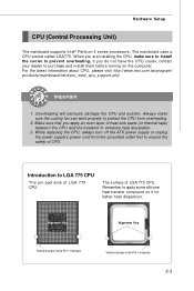
... Pin 1 indicator 2-3 When you apply an even layer of LGA 775 CPU. For the latest information about CPU, please visit http://www.msi.com.tw/program/ products/mainboard/mbd/pro_mbd_cpu_support.php Important 1. Make sure that you are installing the CPU, make sure the cooling fan can...the safety of LGA 775 CPU. While replacing the CPU, always turn off the ATX power supply or unplug the power supply's power cord from overheating. 2. Hardware Setup CPU (Central Processing Unit) The mainboard supports Intel® Pentium 4 series processors. The mainboard uses a CPU socket called LGA775. ...
... Pin 1 indicator 2-3 When you apply an even layer of LGA 775 CPU. For the latest information about CPU, please visit http://www.msi.com.tw/program/ products/mainboard/mbd/pro_mbd_cpu_support.php Important 1. Make sure that you are installing the CPU, make sure the cooling fan can...the safety of LGA 775 CPU. While replacing the CPU, always turn off the ATX power supply or unplug the power supply's power cord from overheating. 2. Hardware Setup CPU (Central Processing Unit) The mainboard supports Intel® Pentium 4 series processors. The mainboard uses a CPU socket called LGA775. ...
User Guide
Page 30
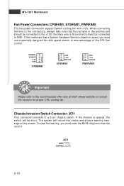
Chassis Intrusion Switch Connector: JCI1 This connector connects to the recommended CPU fans at Intel® official website or consult the vendors for proper CPU cooling fan. The system will be connected to GND. MS-7267 Mainboard Fan Power Connectors: ...
Chassis Intrusion Switch Connector: JCI1 This connector connects to the recommended CPU fans at Intel® official website or consult the vendors for proper CPU cooling fan. The system will be connected to GND. MS-7267 Mainboard Fan Power Connectors: ...

User Guide
Page 31
... connectors for CD-ROM audio. JFP1 10 Power Switch + Power LED 2 9 + Reset - Do not use. 2-15 CD-In Connector: CD_IN1 This connector is compliant with Intel® Front Panel I/O Connectivity Design Guide. HDD 1 +LED JFP2 +8 7 Speaker + 21 Power LED JFP1 Pin Definition PIN SIGNAL 1 HD_LED + 2 FP PW R/SLP 3 HD_LED - 4 FP PW...
... connectors for CD-ROM audio. JFP1 10 Power Switch + Power LED 2 9 + Reset - Do not use. 2-15 CD-In Connector: CD_IN1 This connector is compliant with Intel® Front Panel I/O Connectivity Design Guide. HDD 1 +LED JFP2 +8 7 Speaker + 21 Power LED JFP1 Pin Definition PIN SIGNAL 1 HD_LED + 2 FP PW R/SLP 3 HD_LED - 4 FP PW...
User Guide
Page 32
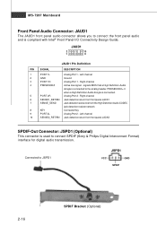
... connector allows you to connect the front panel audio and is connected. 5 PORT 2R Analog Port 2 - PRESENCE# = 0 when a High Definition Audio dongle is compliant with Intel® Front Panel I/O Connectivity Design Guide. Left channel 10 SENSE2_RETIRN Jack detection return from the High Definition Audio CODEC jack detection resistor network 8 KEY Connector...
... connector allows you to connect the front panel audio and is connected. 5 PORT 2R Analog Port 2 - PRESENCE# = 0 when a High Definition Audio dongle is compliant with Intel® Front Panel I/O Connectivity Design Guide. Left channel 10 SENSE2_RETIRN Jack detection return from the High Definition Audio CODEC jack detection resistor network 8 KEY Connector...

User Guide
Page 33
... transfer rate up to a maximum throughput of VCC and GND must be connected correctly to JUSB1/2 USB 2.0 Bracket (Optional) Important Note that are compliant with Intel® I/O Connectivity Design Guide.
... transfer rate up to a maximum throughput of VCC and GND must be connected correctly to JUSB1/2 USB 2.0 Bracket (Optional) Important Note that are compliant with Intel® I/O Connectivity Design Guide.
User Guide
Page 34
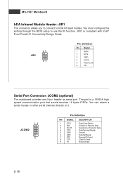
... module. MS-7267 Mainboard IrDA Infrared Module Header: JIR1 The connector allows you to connect to use the IR function. The port is compliant with Intel® Front Panel I/O Connectivity Design Guide. 65 JIR1 21 Pin Definition Pin Signal 1 IRRX 2 IRTX 3 GND 4 VCC5 5 Key (no pin) 6 NC Serial Port Connector: JCOM2...
... module. MS-7267 Mainboard IrDA Infrared Module Header: JIR1 The connector allows you to connect to use the IR function. The port is compliant with Intel® Front Panel I/O Connectivity Design Guide. 65 JIR1 21 Pin Definition Pin Signal 1 IRRX 2 IRTX 3 GND 4 VCC5 5 Key (no pin) 6 NC Serial Port Connector: JCOM2...
User Guide
Page 45
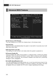
... code in memory by where application code can execute and where it will appear after you installed the CPU which support speedstep technology. 3-8 Intel(R) SpeedStep(tm) tech. The Intel SpeedStep technology allows you to show the company logo on the bootup screen. This field will skip some check items. Bootup Num-Lock...
... code in memory by where application code can execute and where it will appear after you installed the CPU which support speedstep technology. 3-8 Intel(R) SpeedStep(tm) tech. The Intel SpeedStep technology allows you to show the company logo on the bootup screen. This field will skip some check items. Bootup Num-Lock...
