
User Guide
Page 8
Hardware Setup 2-1 Quick Components Guide 2-2 CPU (Central Processing Unit 2-3 Memory ...2-7 Power Supply ...2-8 Back Panel ...2-9 Connectors ...2-11 Jumpers ...2-18 Slots ...2-19 Chapter 3 BIOS Setup ...Activating Dual Core Center A-2 Main ...A-3 DOT (Dynamic OverClocking A-5 Clock ...A-6 Voltage ...A-7 viii CONTENTS Copyright Notice ...ii Trademarks ...ii Revision History ...ii Technical Support ...ii Safety Instructions ...iii FCC-B Radio Frequency Interference Statement iv W EEE (Waste Electrical and Electronic Equipment) Statement v Chapter 1. Getting Started 1-1 Mainboard ...
Hardware Setup 2-1 Quick Components Guide 2-2 CPU (Central Processing Unit 2-3 Memory ...2-7 Power Supply ...2-8 Back Panel ...2-9 Connectors ...2-11 Jumpers ...2-18 Slots ...2-19 Chapter 3 BIOS Setup ...Activating Dual Core Center A-2 Main ...A-3 DOT (Dynamic OverClocking A-5 Clock ...A-6 Voltage ...A-7 viii CONTENTS Copyright Notice ...ii Trademarks ...ii Revision History ...ii Technical Support ...ii Safety Instructions ...iii FCC-B Radio Frequency Interference Statement iv W EEE (Waste Electrical and Electronic Equipment) Statement v Chapter 1. Getting Started 1-1 Mainboard ...
User Guide
Page 11
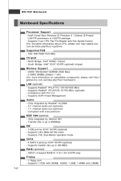
... - Chip integrated by Realtek® ALC888 - 5.1 channel audio-out (optional) - 7.1 channel audio-out (optional) - Supports PIO, Bus Master operation mode SATA - 4 SATA II ports by ICH7/ ICH7R (optional) - South Bridge: Intel® ICH7/ ICH7R (optional) chipset... Specifications Processor Support - SATA1~4 support RAID 0/ 1/ 0+1 (for ICH7R only) Floppy - 1 floppy port - Supports 1 FDD with Fan Speed Control. (For the latest information about CPU, please visit http://global.msi. Supports 4 pin CPU Fan Pin-Header with 360KB, 720KB, 1.2MB, 1.44MB and 2.88MB 1-2 Supports transfer rate ...
... - Chip integrated by Realtek® ALC888 - 5.1 channel audio-out (optional) - 7.1 channel audio-out (optional) - Supports PIO, Bus Master operation mode SATA - 4 SATA II ports by ICH7/ ICH7R (optional) - South Bridge: Intel® ICH7/ ICH7R (optional) chipset... Specifications Processor Support - SATA1~4 support RAID 0/ 1/ 0+1 (for ICH7R only) Floppy - 1 floppy port - Supports 1 FDD with Fan Speed Control. (For the latest information about CPU, please visit http://global.msi. Supports 4 pin CPU Fan Pin-Header with 360KB, 720KB, 1.2MB, 1.44MB and 2.88MB 1-2 Supports transfer rate ...
User Guide
Page 17
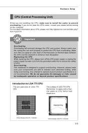
...of thermal paste (or thermal tape) between the CPU and the heatsink to operate beyond product specifications. For the latest information about CPU, please visit http://global.msi.com.tw/index.php? Replaceing the CPU While replacing the CPU, always turn off the ATX power supply or..., while doing overclocking. Hardware Setup CPU (Central Processing Unit) W hen you are installing the CPU, make sure your dealer before turning on it for better heat dispersion. Always make sure the cooling fan can work properly to support overclocking. Alignment Key Alignment Key Yellow...
...of thermal paste (or thermal tape) between the CPU and the heatsink to operate beyond product specifications. For the latest information about CPU, please visit http://global.msi.com.tw/index.php? Replaceing the CPU While replacing the CPU, always turn off the ATX power supply or..., while doing overclocking. Hardware Setup CPU (Central Processing Unit) W hen you are installing the CPU, make sure your dealer before turning on it for better heat dispersion. Always make sure the cooling fan can work properly to support overclocking. Alignment Key Alignment Key Yellow...
User Guide
Page 28
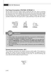
... has a System Hardware Monitor chipset on the screen. You can adjust fan speed in H/W Monitor menu of the CPU fan control. MS-7507 Mainboard Fan Power Connectors: CPUFAN1, SYSFAN1~2 The fan power connectors support system cooling fan with +12V. Chassis Intrusion Connector: JCI1 This connector connects to the connectors, always note that...
... has a System Hardware Monitor chipset on the screen. You can adjust fan speed in H/W Monitor menu of the CPU fan control. MS-7507 Mainboard Fan Power Connectors: CPUFAN1, SYSFAN1~2 The fan power connectors support system cooling fan with +12V. Chassis Intrusion Connector: JCI1 This connector connects to the connectors, always note that...
User Guide
Page 45
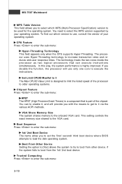
... means to get to load the disk operating system. You need to enter the sub-menu: Hyper-Threading Technology This field appears only when the CPU supports Hyper-Threading. If you disable the f unction, the processor will provide you to set the first/ second/ third boot device where BIOS attempts to it...
... means to get to load the disk operating system. You need to enter the sub-menu: Hyper-Threading Technology This field appears only when the CPU supports Hyper-Threading. If you disable the f unction, the processor will provide you to set the first/ second/ third boot device where BIOS attempts to it...
User Guide
Page 49
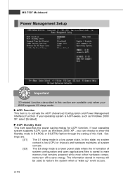
In this state, no system context is lost (CPU or chipset) and hardware maintains all system context. [S3] The S3 sleep mode is a lower power state where the in formation of this section are : [... the setting of system configuration and open applications/files is to save energy. If your operating system is a low power state. If your operating system supports ACPI, such as W indows 2000/ XP, select [Enabled]. MS-7507 Mainboard Power Management Setup Important S3-related functions described in this field. Settings are available...
In this state, no system context is lost (CPU or chipset) and hardware maintains all system context. [S3] The S3 sleep mode is a lower power state where the in formation of this section are : [... the setting of system configuration and open applications/files is to save energy. If your operating system is a low power state. If your operating system supports ACPI, such as W indows 2000/ XP, select [Enabled]. MS-7507 Mainboard Power Management Setup Important S3-related functions described in this field. Settings are available...
User Guide
Page 54
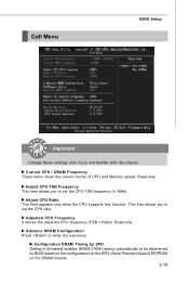
...the SPD (Serial Presence Detect) EEPROM on the DRAM module. 3-19 Read-only. Adjusted CPU Frequency It shows the adjusted CPU frequency (FSB x Ratio). This item allows you to set the CPU ratio. Configuration DRAM Timing by SPD Setting to [Enabled] enables DRAM CAS# Latency automatically... to enter the sub-menu. Adjust CPU FSB Frequency This item allows you are familiar with the chipset. Adjust CPU Ratio This field appears only when the CPU supports this function. Read-only. Cell Menu BIOS Setup Important Change these settings ...
...the SPD (Serial Presence Detect) EEPROM on the DRAM module. 3-19 Read-only. Adjusted CPU Frequency It shows the adjusted CPU frequency (FSB x Ratio). This item allows you to set the CPU ratio. Configuration DRAM Timing by SPD Setting to [Enabled] enables DRAM CAS# Latency automatically... to enter the sub-menu. Adjust CPU FSB Frequency This item allows you are familiar with the chipset. Adjust CPU Ratio This field appears only when the CPU supports this function. Read-only. Cell Menu BIOS Setup Important Change these settings ...


