User Guide
Page 4
... any interference received, including interference that may cause harmful interference to radio communications. This equipment generates, uses and can be used in a particular installation. Micro-Star International MS-7507 This device complies with the limits for a Class B digital device, pursuant to Part 15 of the FCC Rules. If this device must accept any...
... any interference received, including interference that may cause harmful interference to radio communications. This equipment generates, uses and can be used in a particular installation. Micro-Star International MS-7507 This device complies with the limits for a Class B digital device, pursuant to Part 15 of the FCC Rules. If this device must accept any...
User Guide
Page 10
Getting Started Chapter 1 Getting Started Thank you for optimal system efficiency. The 945GCM7 Series mainboards are based on Intel® 945GC & ICH7/ICH7R chipsets for choosing the 945GCM7 Series (MS-7507 v1.X) Micro-ATX mainboard. Designed to fit the advanced Intel® Core 2 Duo/Pentium/Celeron LGA775 processor, the 945GCM7 Series deliver a high performance and professional desktop platform solution. 1-1
Getting Started Chapter 1 Getting Started Thank you for optimal system efficiency. The 945GCM7 Series mainboards are based on Intel® 945GC & ICH7/ICH7R chipsets for choosing the 945GCM7 Series (MS-7507 v1.X) Micro-ATX mainboard. Designed to fit the advanced Intel® Core 2 Duo/Pentium/Celeron LGA775 processor, the 945GCM7 Series deliver a high performance and professional desktop platform solution. 1-1
User Guide
Page 11
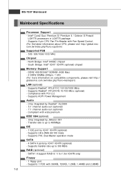
.... (For the latest information about CPU, please visit http://global.msi. t w / index. Supports 4 pin CPU Fan Pin-Header with 360KB, 720KB, 1.2MB, 1.44MB and 2.88MB 1-2 c om . Chip integrated by Realtek® ALC888 - 5.1 channel audio-out (optional) - 7.1 channel audio-out (optional) - MS-7507 Mainboard Mainboard Specifications Processor Support - Supports transfer rate up to 300...
.... (For the latest information about CPU, please visit http://global.msi. t w / index. Supports 4 pin CPU Fan Pin-Header with 360KB, 720KB, 1.2MB, 1.44MB and 2.88MB 1-2 c om . Chip integrated by Realtek® ALC888 - 5.1 channel audio-out (optional) - 7.1 channel audio-out (optional) - MS-7507 Mainboard Mainboard Specifications Processor Support - Supports transfer rate up to 300...
User Guide
Page 13
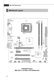
MS-7507 Mainboard Mainboard Layout Top : mouse Bottom:keyboard CPUFAN1 Parallel port Bottom: COM port VGA port ATX1 JPW1 T: 1394 port(optional) B: USB ports Top: LAN Jack ... DIMM2 SATA4 DIMM1 RTM 876-665 BATT + Intel ICH7/ ICH7R(optional) JMicron 381 (optional) JFP2 SATA3 SATA1 SATA2 FDD 1 J1394_1(optional) JBAT1 JFP1 JUSB1 JUSB2 945GCM7 Series (MS-7507 v1.X) Micro-ATX Mainboard 1-4
MS-7507 Mainboard Mainboard Layout Top : mouse Bottom:keyboard CPUFAN1 Parallel port Bottom: COM port VGA port ATX1 JPW1 T: 1394 port(optional) B: USB ports Top: LAN Jack ... DIMM2 SATA4 DIMM1 RTM 876-665 BATT + Intel ICH7/ ICH7R(optional) JMicron 381 (optional) JFP2 SATA3 SATA1 SATA2 FDD 1 J1394_1(optional) JBAT1 JFP1 JUSB1 JUSB2 945GCM7 Series (MS-7507 v1.X) Micro-ATX Mainboard 1-4
User Guide
Page 18
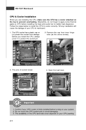
... pins of the CPU land side cover depends on it to protect the socket pin. 2. Remove the cap from damage. The availability of socket reveal. 4. MS-7507 Mainboard CPU & Cooler Installation W hen you install the CPU, always cover it to protect the contact from lever hinge side (as the arrow shows). 3.
... pins of the CPU land side cover depends on it to protect the socket pin. 2. Remove the cap from damage. The availability of socket reveal. 4. MS-7507 Mainboard CPU & Cooler Installation W hen you install the CPU, always cover it to protect the contact from lever hinge side (as the arrow shows). 3.
User Guide
Page 20
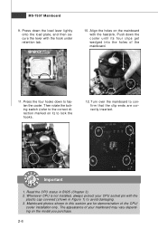
MS-7507 Mainboard 9. Turn over the mainboard to avoid damaging. 3. Whenever CPU is not installed, always protect your mainboard may vary depending on it) to fasten the ...
MS-7507 Mainboard 9. Turn over the mainboard to avoid damaging. 3. Whenever CPU is not installed, always protect your mainboard may vary depending on it) to fasten the ...
User Guide
Page 22
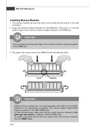
... clip at each side of the same type and density in the DDR2 DIMM slots. - Insert the memory module vertically into the DIM M1 first. 2-8 MS-7507 Mainboard Installing Memory Modules 1.
... clip at each side of the same type and density in the DDR2 DIMM slots. - Insert the memory module vertically into the DIM M1 first. 2-8 MS-7507 Mainboard Installing Memory Modules 1.
User Guide
Page 24
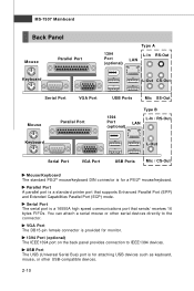
MS-7507 Mainboard Back Panel Mouse Keyboard Parallel Port 1394 Port (optional) Type A L-In RS-Out LAN L-Out CS-Out Serial Port VGA Port Mouse Parallel Port ...
MS-7507 Mainboard Back Panel Mouse Keyboard Parallel Port 1394 Port (optional) Type A L-In RS-Out LAN L-Out CS-Out Serial Port VGA Port Mouse Parallel Port ...
User Guide
Page 26
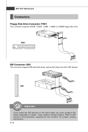
FDD1 IDE Connector: IDE1 This connector supports IDE hard disk drives, optical disk drives and other IDE devices. IDE1 Important If you install two IDE devices on the same cable, you must configure the drives separately to IDE device's documentation supplied by setting jumpers. Refer to master / slave mode by the vendors for jumper setting instructions. 2-12 MS-7507 Mainboard Connectors Floppy Disk Drive Connector: FDD1 This connector supports 360KB, 720KB, 1.2MB, 1.44MB or 2.88MB floppy disk drive.
FDD1 IDE Connector: IDE1 This connector supports IDE hard disk drives, optical disk drives and other IDE devices. IDE1 Important If you install two IDE devices on the same cable, you must configure the drives separately to IDE device's documentation supplied by setting jumpers. Refer to master / slave mode by the vendors for jumper setting instructions. 2-12 MS-7507 Mainboard Connectors Floppy Disk Drive Connector: FDD1 This connector supports 360KB, 720KB, 1.2MB, 1.44MB or 2.88MB floppy disk drive.
User Guide
Page 28
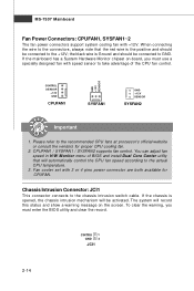
.... Fan cooler set with +12V. Please refer to the +12V; If the chassis is Ground and should be connected to the chassis intrusion switch cable. MS-7507 Mainboard Fan Power Connectors: CPUFAN1, SYSFAN1~2 The fan power connectors support system cooling fan with 3 or 4 pins power connector are both available for proper CPU...
.... Fan cooler set with +12V. Please refer to the +12V; If the chassis is Ground and should be connected to the chassis intrusion switch cable. MS-7507 Mainboard Fan Power Connectors: CPUFAN1, SYSFAN1~2 The fan power connectors support system cooling fan with 3 or 4 pins power connector are both available for proper CPU...
User Guide
Page 30
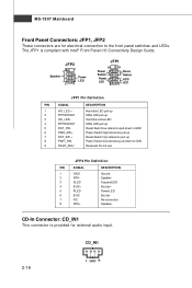
Switch - Do not use. MS-7507 Mainboard Front Panel Connectors: JFP1, JFP2 These connectors are for external audio input. The JFP1 is provided for electrical connection to GND Reserved. JFP2 Pin ...
Switch - Do not use. MS-7507 Mainboard Front Panel Connectors: JFP1, JFP2 These connectors are for external audio input. The JFP1 is provided for electrical connection to GND Reserved. JFP2 Pin ...
User Guide
Page 32
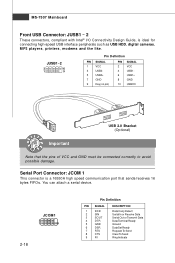
... for connecting high-speed USB interface peripherals such as USB HDD, digital cameras, MP3 players, printers, modems and the like. You can attach a serial device. MS-7507 Mainboard Front USB Connector: JUSB1 ~ 2 These connectors, compliant with Intel® I/O Connectivity Design Guide, is a 16550A high speed communication port that the pins of VCC...
... for connecting high-speed USB interface peripherals such as USB HDD, digital cameras, MP3 players, printers, modems and the like. You can attach a serial device. MS-7507 Mainboard Front USB Connector: JUSB1 ~ 2 These connectors, compliant with Intel® I/O Connectivity Design Guide, is a 16550A high speed communication port that the pins of VCC...
User Guide
Page 34
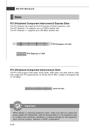
... expansion cards, make sure that comply with PCI specifications. Meanwhile, read the documentation for the expansion card, such as jumpers, switches or BIOS configuration. 2-20 MS-7507 Mainboard Slots PCI (Peripheral Component Interconnect) Express Slots The PCI Express slot supports the PCI Express interface expansion card. PCI Express x16 slot PCI Express...
... expansion cards, make sure that comply with PCI specifications. Meanwhile, read the documentation for the expansion card, such as jumpers, switches or BIOS configuration. 2-20 MS-7507 Mainboard Slots PCI (Peripheral Component Interconnect) Express Slots The PCI Express slot supports the PCI Express interface expansion card. PCI Express x16 slot PCI Express...
User Guide
Page 37
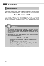
... digit refers to the model number. 6th digit refers to the chipset as I = Intel, N = nVidia, and V = VIA. 7th - 8th digit refers to the customer as MS = all standard customers. Press DEL to enter SETUP If the message disappears before you respond and you still wish to enter Setup, restart the system...
... digit refers to the model number. 6th digit refers to the chipset as I = Intel, N = nVidia, and V = VIA. 7th - 8th digit refers to the customer as MS = all standard customers. Press DEL to enter SETUP If the message disappears before you respond and you still wish to enter Setup, restart the system...
User Guide
Page 39
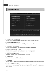
... Fail-Safe Defaults Use this menu to specify your settings for frequency/voltage control and overclocking. H/W Monitor This entry shows your system supports PnP/PCI. MS-7507 Mainboard The Main Menu Standard CMOS Features Use this menu to specify your settings for integrated peripherals. Integrated Peripherals Use this menu for basic system...
... Fail-Safe Defaults Use this menu to specify your settings for frequency/voltage control and overclocking. H/W Monitor This entry shows your system supports PnP/PCI. MS-7507 Mainboard The Main Menu Standard CMOS Features Use this menu to specify your settings for integrated peripherals. Integrated Peripherals Use this menu for basic system...
User Guide
Page 41
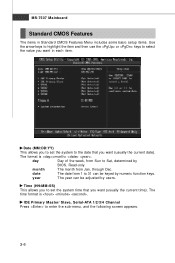
... 1 to 31 can be keyed by numeric function keys. Time (HH:MM :SS) This allows you to set the system to Sat, determined by users. MS-7507 Mainboard Standard CMOS Features The items in each item. IDE Primary Master/ Slave, Serial-ATA 1/2/3/4 Channel Press to select the value you want (usually the...
... 1 to 31 can be keyed by numeric function keys. Time (HH:MM :SS) This allows you to set the system to Sat, determined by users. MS-7507 Mainboard Standard CMOS Features The items in each item. IDE Primary Master/ Slave, Serial-ATA 1/2/3/4 Channel Press to select the value you want (usually the...
User Guide
Page 43
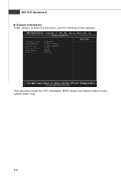
MS-7507 Mainboard System Information Press to enter the sub-menu, and the following screen appears. This sub-menu shows the CPU information, BIOS version and memory status of your system (read only). 3-8
MS-7507 Mainboard System Information Press to enter the sub-menu, and the following screen appears. This sub-menu shows the CPU information, BIOS version and memory status of your system (read only). 3-8
User Guide
Page 45
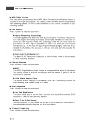
... (Multi-Processor Specification) version to be used for the operating system. VGA Share Memory Size The system shares memory to load the disk operating system. MS-7507 Mainboard MPS Table Version This field allows you to select which version to use only one core to execute the instructions. Boot Sequence Press to...
... (Multi-Processor Specification) version to be used for the operating system. VGA Share Memory Size The system shares memory to load the disk operating system. MS-7507 Mainboard MPS Table Version This field allows you to select which version to use only one core to execute the instructions. Boot Sequence Press to...
User Guide
Page 47
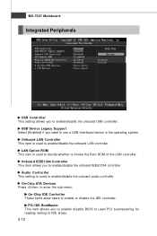
MS-7507 Mainboard Integrated Peripherals USB Controller This setting allows you to enable/disable the onboard IEEE1394 controller. Onboard LAN Controller This item is used PCI busmastering ...
MS-7507 Mainboard Integrated Peripherals USB Controller This setting allows you to enable/disable the onboard IEEE1394 controller. Onboard LAN Controller This item is used PCI busmastering ...
User Guide
Page 49
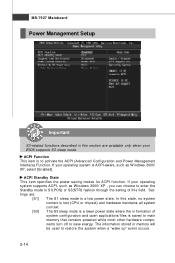
... is saved to main memory that remains powered while most other hardware components turn off to restore the system when a "wake up" event occurs. 3-14 MS-7507 Mainboard Power Management Setup Important S3-related functions described in this section are : [S1] The S1 sleep mode is a low power state.
... is saved to main memory that remains powered while most other hardware components turn off to restore the system when a "wake up" event occurs. 3-14 MS-7507 Mainboard Power Management Setup Important S3-related functions described in this section are : [S1] The S1 sleep mode is a low power state.


