User Guide
Page 8
Getting Started 1-1 Mainboard Specifications 1-2 Mainboard Layout 1-4 Packing Checklist 1-5 Chapter 2. CONTENTS Copyright Notice ...ii Trademarks ...ii Revision History ...ii Technical Support ...ii Safety Instructions ...iii FCC-B Radio Frequency Interference Statement iv W ...
Getting Started 1-1 Mainboard Specifications 1-2 Mainboard Layout 1-4 Packing Checklist 1-5 Chapter 2. CONTENTS Copyright Notice ...ii Trademarks ...ii Revision History ...ii Technical Support ...ii Safety Instructions ...iii FCC-B Radio Frequency Interference Statement iv W ...
User Guide
Page 10
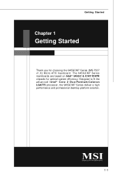
Designed to fit the advanced Intel® Core 2 Duo/Pentium/Celeron LGA775 processor, the 945GCM7 Series deliver a high performance and professional desktop platform solution. 1-1 The 945GCM7 Series mainboards are based on Intel® 945GC & ICH7/ICH7R chipsets for choosing the 945GCM7 Series (MS-7507 v1.X) Micro-ATX mainboard. Getting Started Chapter 1 Getting Started Thank you for optimal system efficiency.
Designed to fit the advanced Intel® Core 2 Duo/Pentium/Celeron LGA775 processor, the 945GCM7 Series deliver a high performance and professional desktop platform solution. 1-1 The 945GCM7 Series mainboards are based on Intel® 945GC & ICH7/ICH7R chipsets for choosing the 945GCM7 Series (MS-7507 v1.X) Micro-ATX mainboard. Getting Started Chapter 1 Getting Started Thank you for optimal system efficiency.
User Guide
Page 11
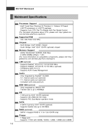
...7.1 channel audio-out (optional) - Supports 1 FDD with Fan Speed Control. (For the latest information about CPU, please visit http://global.msi. Supports ACPI Power Management Audio - Transfer rate is up to 400Mbps IDE - 1 IDE port by ICH7/ ICH7R (optional) - Supports ...800/1066/1333 MHz Chipset - Supports Realtek® RTL8111C 10/100/1000 Mb/s - Compliance with vista premium IEEE 1394 (optional) - MS-7507 Mainboard Mainboard Specifications Processor Support - Intel® Core2 Duo/ Pemtium D/ Pemtium 4 / Celeron D Presott LGA775 processors in LGA775 package. - c om . ...
...7.1 channel audio-out (optional) - Supports 1 FDD with Fan Speed Control. (For the latest information about CPU, please visit http://global.msi. Supports ACPI Power Management Audio - Transfer rate is up to 400Mbps IDE - 1 IDE port by ICH7/ ICH7R (optional) - Supports ...800/1066/1333 MHz Chipset - Supports Realtek® RTL8111C 10/100/1000 Mb/s - Compliance with vista premium IEEE 1394 (optional) - MS-7507 Mainboard Mainboard Specifications Processor Support - Intel® Core2 Duo/ Pemtium D/ Pemtium 4 / Celeron D Presott LGA775 processors in LGA775 package. - c om . ...
User Guide
Page 13
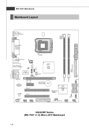
MS-7507 Mainboard Mainboard Layout Top : mouse Bottom:keyboard CPUFAN1 Parallel port Bottom: COM port VGA port ATX1 JPW1 T: 1394 port(optional) B: USB ports Top: LAN Jack Bottom: USB ... DIMM2 SATA4 DIMM1 RTM 876-665 BATT + Intel ICH7/ ICH7R(optional) JMicron 381 (optional) JFP2 SATA3 SATA1 SATA2 FDD 1 J1394_1(optional) JBAT1 JFP1 JUSB1 JUSB2 945GCM7 Series (MS-7507 v1.X) Micro-ATX Mainboard 1-4
MS-7507 Mainboard Mainboard Layout Top : mouse Bottom:keyboard CPUFAN1 Parallel port Bottom: COM port VGA port ATX1 JPW1 T: 1394 port(optional) B: USB ports Top: LAN Jack Bottom: USB ... DIMM2 SATA4 DIMM1 RTM 876-665 BATT + Intel ICH7/ ICH7R(optional) JMicron 381 (optional) JFP2 SATA3 SATA1 SATA2 FDD 1 J1394_1(optional) JBAT1 JFP1 JUSB1 JUSB2 945GCM7 Series (MS-7507 v1.X) Micro-ATX Mainboard 1-4
User Guide
Page 17
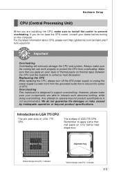
...product specifications. Remember to apply some thermal paste on the computer. Replaceing the CPU While replacing the CPU, always turn off the ATX power supply or unplug the power supply's power cord from overheating. Hardware Setup CPU (Central Processing Unit) W hen you apply an... the CPU and the heatsink to enhance heat dissipation. For the latest information about CPU, please visit http://global.msi.com.tw/index.php? Overclocking This mainboard is the Pin 1 indicator 2-3 However, please make sure the cooling fan can work properly to support overclocking. Alignment...
...product specifications. Remember to apply some thermal paste on the computer. Replaceing the CPU While replacing the CPU, always turn off the ATX power supply or unplug the power supply's power cord from overheating. Hardware Setup CPU (Central Processing Unit) W hen you apply an... the CPU and the heatsink to enhance heat dissipation. For the latest information about CPU, please visit http://global.msi.com.tw/index.php? Overclocking This mainboard is the Pin 1 indicator 2-3 However, please make sure the cooling fan can work properly to support overclocking. Alignment...
User Guide
Page 18
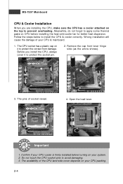
W rong installation will cause the damage of your CPU packing. 2-4 Important 1. The pins of the CPU land side cover depends on your CPU & mainboard. 1. Confirm if your system. 2. Open the load lever. Do not touch the CPU socket pins to protect the socket pin. 2. Remove the cap ... cap on it to avoid damaging. 3. Meanwhile, do not forget to protect the contact from lever hinge side (as the arrow shows). 3. MS-7507 Mainboard CPU & Cooler Installation W hen you install the CPU, always cover it to apply some thermal paste on CPU before turning on your CPU cooler is...
W rong installation will cause the damage of your CPU packing. 2-4 Important 1. The pins of the CPU land side cover depends on your CPU & mainboard. 1. Confirm if your system. 2. Open the load lever. Do not touch the CPU socket pins to protect the socket pin. 2. Remove the cap ... cap on it to avoid damaging. 3. Meanwhile, do not forget to protect the contact from lever hinge side (as the arrow shows). 3. MS-7507 Mainboard CPU & Cooler Installation W hen you install the CPU, always cover it to apply some thermal paste on CPU before turning on your CPU cooler is...
User Guide
Page 20
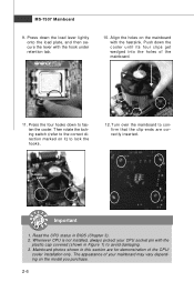
... confirm that the clip-ends are for demonstration of the CPU/ cooler installation only. Mainboard photos shown in this section are correctly inserted. Press the four hooks down the cooler until its four clips get wedged into the holes of ... switch (refer to fasten the cooler. Whenever CPU is not installed, always protect your mainboard may vary depending on the model you purchase. 2-6 The appearance of the mainboard. 11. Push down to the correct direction marked on the mainboard with the heatsink. locking switch Important 1. Press down the load lever lightly onto the...
... confirm that the clip-ends are for demonstration of the CPU/ cooler installation only. Mainboard photos shown in this section are correctly inserted. Press the four hooks down the cooler until its four clips get wedged into the holes of ... switch (refer to fasten the cooler. Whenever CPU is not installed, always protect your mainboard may vary depending on the model you purchase. 2-6 The appearance of the mainboard. 11. Push down to the correct direction marked on the mainboard with the heatsink. locking switch Important 1. Press down the load lever lightly onto the...
User Guide
Page 22
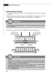
... the golden finger on the center and will automatically close. Insert the memory module vertically into the DIM M1 first. 2-8 Volt Notch Important - MS-7507 Mainboard Installing Memory Modules 1. The memory module has only one notch on the memory module is not backwards compatible. The plastic clip at each side of...
... the golden finger on the center and will automatically close. Insert the memory module vertically into the DIM M1 first. 2-8 Volt Notch Important - MS-7507 Mainboard Installing Memory Modules 1. The memory module has only one notch on the memory module is not backwards compatible. The plastic clip at each side of...
User Guide
Page 23
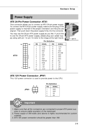
...push down the power supply firmly into the connector. Hardware Setup Power Supply ATX 24-Pin Power Connector: ATX1 This connector allows you like to use the 20-pin ATX power supply as you to ensure stable operation of the mainboard. 2. JPW1 42 31 Pin Definition PIN SIGNAL 1 GND 2 GND 3... 12V 4 12V pin 13 pin 12 Important 1. Power supply of the power supply is inserted in the proper orientation and the pins are connected to proper ATX power supplies to connect an ATX 24-pin power...
...push down the power supply firmly into the connector. Hardware Setup Power Supply ATX 24-Pin Power Connector: ATX1 This connector allows you like to use the 20-pin ATX power supply as you to ensure stable operation of the mainboard. 2. JPW1 42 31 Pin Definition PIN SIGNAL 1 GND 2 GND 3... 12V 4 12V pin 13 pin 12 Important 1. Power supply of the power supply is inserted in the proper orientation and the pins are connected to proper ATX power supplies to connect an ATX 24-pin power...
User Guide
Page 24
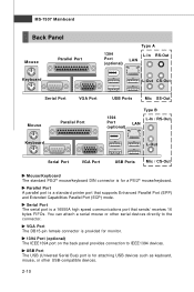
... panel provides connection to the connector. VGA Port The DB15-pin female connector is a standard printer port that sends/ receives 16 bytes FIFOs. MS-7507 Mainboard Back Panel Mouse Keyboard Parallel Port 1394 Port (optional) Type A L-In RS-Out LAN L-Out CS-Out Serial Port VGA Port Mouse Parallel Port USB...
... panel provides connection to the connector. VGA Port The DB15-pin female connector is a standard printer port that sends/ receives 16 bytes FIFOs. MS-7507 Mainboard Back Panel Mouse Keyboard Parallel Port 1394 Port (optional) Type A L-In RS-Out LAN L-Out CS-Out Serial Port VGA Port Mouse Parallel Port USB...
User Guide
Page 26
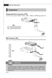
IDE1 Important If you install two IDE devices on the same cable, you must configure the drives separately to IDE device's documentation supplied by setting jumpers. FDD1 IDE Connector: IDE1 This connector supports IDE hard disk drives, optical disk drives and other IDE devices. Refer to master / slave mode by the vendors for jumper setting instructions. 2-12 MS-7507 Mainboard Connectors Floppy Disk Drive Connector: FDD1 This connector supports 360KB, 720KB, 1.2MB, 1.44MB or 2.88MB floppy disk drive.
IDE1 Important If you install two IDE devices on the same cable, you must configure the drives separately to IDE device's documentation supplied by setting jumpers. FDD1 IDE Connector: IDE1 This connector supports IDE hard disk drives, optical disk drives and other IDE devices. Refer to master / slave mode by the vendors for jumper setting instructions. 2-12 MS-7507 Mainboard Connectors Floppy Disk Drive Connector: FDD1 This connector supports 360KB, 720KB, 1.2MB, 1.44MB or 2.88MB floppy disk drive.
User Guide
Page 28
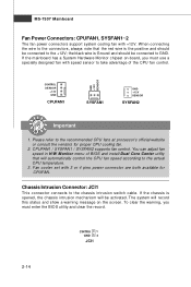
... This connector connects to the actual CPU temperature. 3. To clear the warning, you must enter the BIOS utility and clear the record. If the mainboard has a System Hardware Monitor chipset on the screen. GND +1 2V S E NS OR CONTROL SE NS OR +1 2V GND CPUFAN1 SYSFAN1 GND ...with 3 or 4 pins power connector are both available for proper CPU cooling fan. 2. CPUFAN1 / SYSFAN1 / SYSFAN2 supports fan control. MS-7507 Mainboard Fan Power Connectors: CPUFAN1, SYSFAN1~2 The fan power connectors support system cooling fan with +12V. the black wire is the positive and should be connected...
... This connector connects to the actual CPU temperature. 3. To clear the warning, you must enter the BIOS utility and clear the record. If the mainboard has a System Hardware Monitor chipset on the screen. GND +1 2V S E NS OR CONTROL SE NS OR +1 2V GND CPUFAN1 SYSFAN1 GND ...with 3 or 4 pins power connector are both available for proper CPU cooling fan. 2. CPUFAN1 / SYSFAN1 / SYSFAN2 supports fan control. MS-7507 Mainboard Fan Power Connectors: CPUFAN1, SYSFAN1~2 The fan power connectors support system cooling fan with +12V. the black wire is the positive and should be connected...
User Guide
Page 30
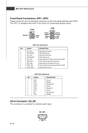
... compliant with Intel® Front Panel I/O Connectivity Design Guide. The JFP1 is provided for electrical connection to GND Reserved. Switch - Do not use. MS-7507 Mainboard Front Panel Connectors: JFP1, JFP2 These connectors are for external audio input.
... compliant with Intel® Front Panel I/O Connectivity Design Guide. The JFP1 is provided for electrical connection to GND Reserved. Switch - Do not use. MS-7507 Mainboard Front Panel Connectors: JFP1, JFP2 These connectors are for external audio input.
User Guide
Page 32
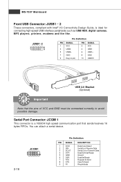
...+ 7 GND 9 Key (no pin) PIN SIGNAL 2 VCC 4 USB1- 6 USB1+ 8 GND 10 USBOC USB 2.0 Bracket (Optional) Important Note that sends/receives 16 bytes FIFOs. MS-7507 Mainboard Front USB Connector: JUSB1 ~ 2 These connectors, compliant with Intel® I/O Connectivity Design Guide, is a 16550A high speed communication port that the pins of VCC and...
...+ 7 GND 9 Key (no pin) PIN SIGNAL 2 VCC 4 USB1- 6 USB1+ 8 GND 10 USBOC USB 2.0 Bracket (Optional) Important Note that sends/receives 16 bytes FIFOs. MS-7507 Mainboard Front USB Connector: JUSB1 ~ 2 These connectors, compliant with Intel® I/O Connectivity Design Guide, is a 16550A high speed communication port that the pins of VCC and...
User Guide
Page 33
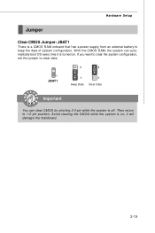
Avoid clearing the CMOS while the system is on . it is turned on ; Hardware Setup Jumper Clear CMOS Jumper: JBAT1 There is a CMOS RAM onboard that has a power supply from an external battery to 1-2 pin position. If you want to clear the system configuration, set the jumper to clear data. 3 3 1 JBAT1 1 1 Keep Data Clear Data Important You can automatically boot OS every time it will damage the mainboard. 2-19 W ith the CMOS RAM, the system can clear CMOS by shorting 2-3 pin while the system is off. Then return to keep the data of system configuration.
Avoid clearing the CMOS while the system is on . it is turned on ; Hardware Setup Jumper Clear CMOS Jumper: JBAT1 There is a CMOS RAM onboard that has a power supply from an external battery to 1-2 pin position. If you want to clear the system configuration, set the jumper to clear data. 3 3 1 JBAT1 1 1 Keep Data Clear Data Important You can automatically boot OS every time it will damage the mainboard. 2-19 W ith the CMOS RAM, the system can clear CMOS by shorting 2-3 pin while the system is off. Then return to keep the data of system configuration.
User Guide
Page 34
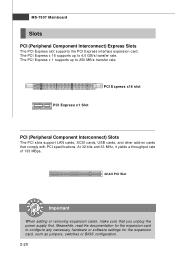
..., make sure that comply with PCI specifications. Meanwhile, read the documentation for the expansion card, such as jumpers, switches or BIOS configuration. 2-20 MS-7507 Mainboard Slots PCI (Peripheral Component Interconnect) Express Slots The PCI Express slot supports the PCI Express interface expansion card. The PCI Express x 1 supports up to configure...
..., make sure that comply with PCI specifications. Meanwhile, read the documentation for the expansion card, such as jumpers, switches or BIOS configuration. 2-20 MS-7507 Mainboard Slots PCI (Peripheral Component Interconnect) Express Slots The PCI Express slot supports the PCI Express interface expansion card. The PCI Express x 1 supports up to configure...
User Guide
Page 37
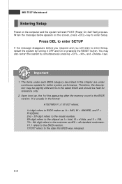
... continuous update for reference only. 2. Upon boot-up, the 1st line appearing after the memory count is usually in this BIOS was released. 3-2 MS-7507 Mainboard Entering Setup Power on the screen, press key to the date this chapter are under each BIOS category described in the format: A7507IMS V1.0 101007...
... continuous update for reference only. 2. Upon boot-up, the 1st line appearing after the memory count is usually in this BIOS was released. 3-2 MS-7507 Mainboard Entering Setup Power on the screen, press key to the date this chapter are under each BIOS category described in the format: A7507IMS V1.0 101007...
User Guide
Page 39
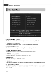
... Setup Use this menu to setup the items of AMI® special enhanced features. H/W Monitor This entry shows your system supports PnP/PCI. MS-7507 Mainboard The Main Menu Standard CMOS Features Use this menu for power management. Load Fail-Safe Defaults Use this menu to specify your settings for frequency...
... Setup Use this menu to setup the items of AMI® special enhanced features. H/W Monitor This entry shows your system supports PnP/PCI. MS-7507 Mainboard The Main Menu Standard CMOS Features Use this menu for power management. Load Fail-Safe Defaults Use this menu to specify your settings for frequency...
User Guide
Page 40
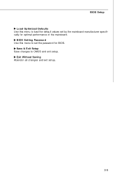
Save & Exit Setup Save changes to load the default values set the password for optimal performance of the mainboard. BIOS Setup Load Optimized Defaults Use this menu to set by the mainboard manufacturer specifically for BIOS. Exit Without Saving Abandon all changes and exit setup. 3-5 BIOS Setting Password Use this menu to CMOS and exit setup.
Save & Exit Setup Save changes to load the default values set the password for optimal performance of the mainboard. BIOS Setup Load Optimized Defaults Use this menu to set by the mainboard manufacturer specifically for BIOS. Exit Without Saving Abandon all changes and exit setup. 3-5 BIOS Setting Password Use this menu to CMOS and exit setup.
User Guide
Page 41
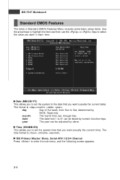
...). The format is . through Dec. IDE Primary Master/ Slave, Serial-ATA 1/2/3/4 Channel Press to Sat, determined by users. date The date from Jan. MS-7507 Mainboard Standard CMOS Features The items in each item. Read-only. The time format is . Date (MM:DD:YY) This allows you to set the system...
...). The format is . through Dec. IDE Primary Master/ Slave, Serial-ATA 1/2/3/4 Channel Press to Sat, determined by users. date The date from Jan. MS-7507 Mainboard Standard CMOS Features The items in each item. Read-only. The time format is . Date (MM:DD:YY) This allows you to set the system...


