User Guide
Page 8
... 4/ Celeron D LGA 775 processors (For the latest information about CPU, please visit http://global.msi.com.tw/index.php?func=cpuform) Supported FSB l 800 / 533 MHz Chipset l North Bridge: Intel® 945GC chipset l South Bridge: Intel® ICH7 chipset Memory Support l DDR2 400/ 533/ 667 SDRAM (4GB Max) l 2...DIMMs (240pin/ 1.8V) (For more information on compatible components, please visit http://global.msi.com.tw/index.php?func=testreport) LAN l Supports 10/100 Mb/s Fast Ethernet by Realtek RTL 8101E l Or Supports 10/100/1000 Mb/s Fast Ethermet by Realtek RTL 8111B Audio l Chip integrated by ...
... 4/ Celeron D LGA 775 processors (For the latest information about CPU, please visit http://global.msi.com.tw/index.php?func=cpuform) Supported FSB l 800 / 533 MHz Chipset l North Bridge: Intel® 945GC chipset l South Bridge: Intel® ICH7 chipset Memory Support l DDR2 400/ 533/ 667 SDRAM (4GB Max) l 2...DIMMs (240pin/ 1.8V) (For more information on compatible components, please visit http://global.msi.com.tw/index.php?func=testreport) LAN l Supports 10/100 Mb/s Fast Ethernet by Realtek RTL 8101E l Or Supports 10/100/1000 Mb/s Fast Ethermet by Realtek RTL 8111B Audio l Chip integrated by ...
User Guide
Page 11
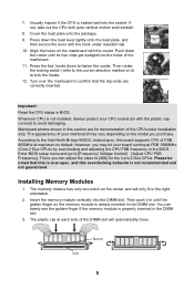
... North Bridge 945GC chipset spec, this overclocking behavior is over-spec, and this board supports CPU of your mainboard may let your CPU socket pin with the hook under retention tab. 10. Important: Read the CPU status in until its four clips get wedged into the holes of the mainboard. 11... load lever lightly onto the load plate, and then secure the lever with the plastic cap covered to [Frequency/ Voltage Control]à[Adjust CPU FSB Frequency]. Press the four hooks down to the correct direction marked on the center and will automatically close. Then rotate the locking switch...
... North Bridge 945GC chipset spec, this overclocking behavior is over-spec, and this board supports CPU of your mainboard may let your CPU socket pin with the hook under retention tab. 10. Important: Read the CPU status in until its four clips get wedged into the holes of the mainboard. 11... load lever lightly onto the load plate, and then secure the lever with the plastic cap covered to [Frequency/ Voltage Control]à[Adjust CPU FSB Frequency]. Press the four hooks down to the correct direction marked on the center and will automatically close. Then rotate the locking switch...
User Guide
Page 12
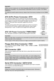
... 20-pin ATX power supply,...20-pin ATX power supply as you to one Serial ATA device. Floppy Disk Drive Connector: FDD1 This connector supports 360KB,...the connectors are aligned. IDE Connector: IDE1 This connector supports IDE hard disk drives, optical disk drives and other ...highly recommended for jumper setting instructions. To connect the ATX 24-pin power supply, make sure the plug ... orientation and the pins are connected to proper ATX power supplies to ensure stable operation of the... 5VSB +12V +12V +3.3V ATX 12V Power Connector: PWRCONN1 +12V +12V This 12V power connector is used to...
... 20-pin ATX power supply,...20-pin ATX power supply as you to one Serial ATA device. Floppy Disk Drive Connector: FDD1 This connector supports 360KB,...the connectors are aligned. IDE Connector: IDE1 This connector supports IDE hard disk drives, optical disk drives and other ...highly recommended for jumper setting instructions. To connect the ATX 24-pin power supply, make sure the plug ... orientation and the pins are connected to proper ATX power supplies to ensure stable operation of the... 5VSB +12V +12V +3.3V ATX 12V Power Connector: PWRCONN1 +12V +12V This 12V power connector is used to...
User Guide
Page 13
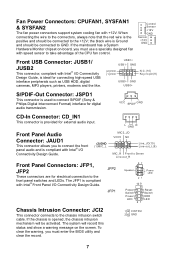
... -- + -+ Power Reset Switch Switch Power HDD LED LED 21 Chassis Intrusion Connector: JCI2 This connector connects to take advantage of the CPU fan control. Control Sensor +12V GND Sensor +12V GND Front USB Connector: JUSB1/ JUSB2 This connector, compliant with Intel® I/O ... designed fan with Intel® Front Panel I/O Connectivity Design Guide. Fan Power Connectors: CPUFAN1, SYSFAN1 & SYSFAN2 The fan power connectors support system cooling fan with Intel® I/O Connectivity Design Guide. (2)GND (1)MIC_L MIC2_JD VCC5 NC Line_JD(10) Line-out_L(9) MIC_R Front to...
... -- + -+ Power Reset Switch Switch Power HDD LED LED 21 Chassis Intrusion Connector: JCI2 This connector connects to take advantage of the CPU fan control. Control Sensor +12V GND Sensor +12V GND Front USB Connector: JUSB1/ JUSB2 This connector, compliant with Intel® I/O ... designed fan with Intel® Front Panel I/O Connectivity Design Guide. Fan Power Connectors: CPUFAN1, SYSFAN1 & SYSFAN2 The fan power connectors support system cooling fan with Intel® I/O Connectivity Design Guide. (2)GND (1)MIC_L MIC2_JD VCC5 NC Line_JD(10) Line-out_L(9) MIC_R Front to...
User Guide
Page 15
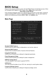
...Main Page Standard CMOS Features Use this menu to specify your settings for overall system status. PNP/PCI Configurations This entry appears if your CPU, fan, warning for power management. Power Management Setup Use this menu to specify your settings for frequency/voltage control. 9 You may also...turning it OFF and On or pressing the RESET button. Frequency/Voltage Control Use this menu to setup the items of your system supports PnP/PCI. Advanced BIOS Features Use this menu to specify your settings for integrated peripherals. When the message below appears on the ...
...Main Page Standard CMOS Features Use this menu to specify your settings for overall system status. PNP/PCI Configurations This entry appears if your CPU, fan, warning for power management. Power Management Setup Use this menu to specify your settings for frequency/voltage control. 9 You may also...turning it OFF and On or pressing the RESET button. Frequency/Voltage Control Use this menu to setup the items of your system supports PnP/PCI. Advanced BIOS Features Use this menu to specify your settings for integrated peripherals. When the message below appears on the ...


