

User Guide
Page 2
... this device must accept any , must be required to cause harmful interference, in accordance with Part 15 of the FCC rules. Micro-Star International MS-7133 This device complies with the instruction manual, may not cause harmful interference, and (2) this equipment in a residential area is operated in order to comply with...
... this device must accept any , must be required to cause harmful interference, in accordance with Part 15 of the FCC rules. Micro-Star International MS-7133 This device complies with the instruction manual, may not cause harmful interference, and (2) this equipment in a residential area is operated in order to comply with...

User Guide
Page 8
Getting Started Chapter 1. Getting Started Getting Started Thank you for optimal system efficiency. Designed to fit the advanced Intel® Pentium 4/Celeron-D Prescott (LGA775)processor, the 915PM4/915GM4/ 915GVM4/915GLM4/915PLM4 mainboard delivers a high performance and professional desktop platform solution. 1-1 The 915PM4/915GM 4/915GVM4/915GLM4/915PLM4 mainboard is based on Intel® 915P/G/GV/GL/PL and Intel® ICH6 chipset for choosing the 915PM4/915GM 4/915GVM4/ 915GLM 4/915PLM 4 (MS-7133) v1.X M-ATX mainboard.
Getting Started Chapter 1. Getting Started Getting Started Thank you for optimal system efficiency. Designed to fit the advanced Intel® Pentium 4/Celeron-D Prescott (LGA775)processor, the 915PM4/915GM4/ 915GVM4/915GLM4/915PLM4 mainboard delivers a high performance and professional desktop platform solution. 1-1 The 915PM4/915GM 4/915GVM4/915GLM4/915PLM4 mainboard is based on Intel® 915P/G/GV/GL/PL and Intel® ICH6 chipset for choosing the 915PM4/915GM 4/915GVM4/ 915GLM 4/915PLM 4 (MS-7133) v1.X M-ATX mainboard.
User Guide
Page 9
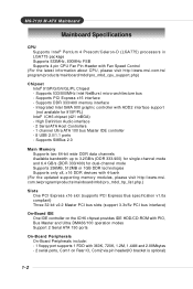
M S-7133 M -ATX M ainboard Mainboard Specifications CPU † Supports Intel® Pentium 4 Prescott/Celeron-D (LGA775) processors in LGA775 package † Supports 533MHz, 800MHz FSB † Supports 4 pin CPU Fan Pin-Header with 4-bank (For the updated supporting memory modules, please visit http://www.msi. Supports ...† Supports only x8, x16 DDR devices with Fan Speed Control (For the latest information about CPU, please visit http://www.msi.com.tw/ prog ram/produc ts / mainboard/mbd/ pro_mbd _c pu_s upport. com.tw/program/products/mainboard/mbd/pro_mbd_trp_list.php.) Slots...
M S-7133 M -ATX M ainboard Mainboard Specifications CPU † Supports Intel® Pentium 4 Prescott/Celeron-D (LGA775) processors in LGA775 package † Supports 533MHz, 800MHz FSB † Supports 4 pin CPU Fan Pin-Header with 4-bank (For the updated supporting memory modules, please visit http://www.msi. Supports ...† Supports only x8, x16 DDR devices with Fan Speed Control (For the latest information about CPU, please visit http://www.msi.com.tw/ prog ram/produc ts / mainboard/mbd/ pro_mbd _c pu_s upport. com.tw/program/products/mainboard/mbd/pro_mbd_trp_list.php.) Slots...

User Guide
Page 16
... until you are installing the CPU, make sure the CPU has a heat sink/ cooler fan attached on the top to protect the contac t f rom damage. M S-7133 M -ATX M ainboard CPU, Heatsink & Fan Installation W hen you are going to install the CPU & cooling fan correctly. Meanwhile, do not have the heat sink/cooler...
... until you are installing the CPU, make sure the CPU has a heat sink/ cooler fan attached on the top to protect the contac t f rom damage. M S-7133 M -ATX M ainboard CPU, Heatsink & Fan Installation W hen you are going to install the CPU & cooling fan correctly. Meanwhile, do not have the heat sink/cooler...
User Guide
Page 18
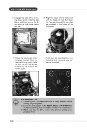
...pins are corrected inserted. Press the four hooks down lightly onto the load plate, and then secure the lever with the heatsink first. locking switch MSI Reminds You... 1. Align the holes on the mainboard with the hook under retention tab. 10. Turn over the mainboard to fasten the fan.... not turned up or pressed down the fan/heatsink until its four clips get wedged in BIOS (refer to lock the hooks again. 12. M S-7133 M -ATX M ainboard 9. Then rotate the locking switch (refer to the correct direction marked on your CPU heatsink/cooler is firmly installed before turning ...
...pins are corrected inserted. Press the four hooks down lightly onto the load plate, and then secure the lever with the heatsink first. locking switch MSI Reminds You... 1. Align the holes on the mainboard with the hook under retention tab. 10. Turn over the mainboard to fasten the fan.... not turned up or pressed down the fan/heatsink until its four clips get wedged in BIOS (refer to lock the hooks again. 12. M S-7133 M -ATX M ainboard 9. Then rotate the locking switch (refer to the correct direction marked on your CPU heatsink/cooler is firmly installed before turning ...

User Guide
Page 20
... any order to meet your own needs. You can barely see the golden finger if the module is deeply inserted in the socket. 3. Volt Notch MSI Reminds You... The plastic clip at least one notch on the memory module is properly inserted in the socket. 2-8 Then push it in until the... golden finger on the center of the DIMM slot will only fit in the right orientation. 2. M S-7133 M -ATX M ainboard DIMM Module Combination Install at each side of module. The module will automatically close.
... any order to meet your own needs. You can barely see the golden finger if the module is deeply inserted in the socket. 3. Volt Notch MSI Reminds You... The plastic clip at least one notch on the memory module is properly inserted in the socket. 2-8 Then push it in until the... golden finger on the center of the DIMM slot will only fit in the right orientation. 2. M S-7133 M -ATX M ainboard DIMM Module Combination Install at each side of module. The module will automatically close.

User Guide
Page 22
M S-7133 M -ATX M ainboard Back Panel The back panel provides the following connectors: M ou se IEEE1394 Parallel LAN L-In Surround Center/ Subwoofer Keyboard USB Ports COM port ...
M S-7133 M -ATX M ainboard Back Panel The back panel provides the following connectors: M ou se IEEE1394 Parallel LAN L-In Surround Center/ Subwoofer Keyboard USB Ports COM port ...
User Guide
Page 24
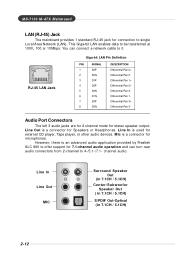
... by Realtek ALC 880 to offer support for 7.1-channel audio operation and can connect a network cable to 4-/5.1-/7.1- However, there is a connector for Speakers or Headphones. M S-7133 M -ATX M ainboard LAN (RJ-45) Jack The mainboard provides 1 standard RJ-45 jack for connection to be transferred at 1000, 100 or 10Mbps. Line In...
... by Realtek ALC 880 to offer support for 7.1-channel audio operation and can connect a network cable to 4-/5.1-/7.1- However, there is a connector for Speakers or Headphones. M S-7133 M -ATX M ainboard LAN (RJ-45) Jack The mainboard provides 1 standard RJ-45 jack for connection to be transferred at 1000, 100 or 10Mbps. Line In...

User Guide
Page 26
... CPU cooling fan. 2. If the mainboard has a System Hardware Monitor chipset on-board, you must use a specially designed fan with +12V. M S-7133 M -ATX M ainboard Connectors The mainboard provides connectors to connect to take note that supports 360K, 720K, 1.2M, 1.44M and 2.88M floppy disk ...connecting the wire to the connectors, always take advantage of the CPU fan control. GND +12V SENSOR Control CPUFAN1 GND +12V Sensor SYSFAN1 MSI Reminds You... 1. Floppy Disk Drive Connector: FDD1 The mainboard provides a standard floppy disk drive connector that the red wire is the positive...
... CPU cooling fan. 2. If the mainboard has a System Hardware Monitor chipset on-board, you must use a specially designed fan with +12V. M S-7133 M -ATX M ainboard Connectors The mainboard provides connectors to connect to take note that supports 360K, 720K, 1.2M, 1.44M and 2.88M floppy disk ...connecting the wire to the connectors, always take advantage of the CPU fan control. GND +12V SENSOR Control CPUFAN1 GND +12V Sensor SYSFAN1 MSI Reminds You... 1. Floppy Disk Drive Connector: FDD1 The mainboard provides a standard floppy disk drive connector that the red wire is the positive...

User Guide
Page 28
Each Serial ATA connector can connect to the hard disk d evi c es MSI Reminds You... SATA1 1 7 SATA2 1 7 SATA1/SATA2 Pin Definition PIN SIGNAL 1 GND 3 TXN 5 RXN 7 GND PIN SIGNAL 2 TXP 4 GND 6 RXP Serial ATA cable Connect to serial ... not fold the serial ATA cable in a 90-degree angle, which will cause the loss of 150MB/s and are fully compliant with Serial ATA 1.0 specifications. M S-7133 M -ATX M ainboard Serial ATA HDD Connectors: SATA1 & SATA2 The mainboard provides dual high-speed Serial ATA interface ports. The ports support 1st generation Serial ATA...
Each Serial ATA connector can connect to the hard disk d evi c es MSI Reminds You... SATA1 1 7 SATA2 1 7 SATA1/SATA2 Pin Definition PIN SIGNAL 1 GND 3 TXN 5 RXN 7 GND PIN SIGNAL 2 TXP 4 GND 6 RXP Serial ATA cable Connect to serial ... not fold the serial ATA cable in a 90-degree angle, which will cause the loss of 150MB/s and are fully compliant with Serial ATA 1.0 specifications. M S-7133 M -ATX M ainboard Serial ATA HDD Connectors: SATA1 & SATA2 The mainboard provides dual high-speed Serial ATA interface ports. The ports support 1st generation Serial ATA...
User Guide
Page 30
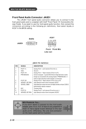
... line-out R) 6 SENSE1_RETIRN Jack detection return from front panel JACK1 7 SENSE_SEND Jack detection sense line from front panel JACK2 2-18 MSI Reminds You... signals BIOS that a High Definition Audio dongle is compliant with Intel® Front Panel I/O Connectivity Design Guide. If ... Jack detection return from the High Definition Audio CODEC jack detection resistor network 8 KEY Connector Key 9 PORT 2L Analog Port 2 - M S-7133 M -ATX M ainboard Front Panel Audio Connector: JAUD1 The JAUD1 front panel audio connector allows you to connect to the front panel audio and...
... line-out R) 6 SENSE1_RETIRN Jack detection return from front panel JACK1 7 SENSE_SEND Jack detection sense line from front panel JACK2 2-18 MSI Reminds You... signals BIOS that a High Definition Audio dongle is compliant with Intel® Front Panel I/O Connectivity Design Guide. If ... Jack detection return from the High Definition Audio CODEC jack detection resistor network 8 KEY Connector Key 9 PORT 2L Analog Port 2 - M S-7133 M -ATX M ainboard Front Panel Audio Connector: JAUD1 The JAUD1 front panel audio connector allows you to connect to the front panel audio and...
User Guide
Page 32
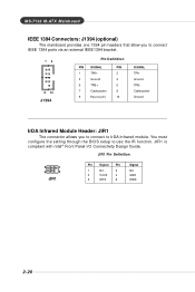
... the setting through the BIOS setup to IrDA Infrared module. JIR1 Pin Definition 5 1 6 2 JIR1 Pin Signal Pin 1 NC 2 3 VCC5 4 5 IRTX 6 Signal NC GND IRRX 2-20 M S-7133 M -ATX M ainboard IEEE 1394 Connectors: J1394 (optional) The mainboard provides one 1394 pin headers that allow you to connect IEEE 1394 ports via an external...
... the setting through the BIOS setup to IrDA Infrared module. JIR1 Pin Definition 5 1 6 2 JIR1 Pin Signal Pin 1 NC 2 3 VCC5 4 5 IRTX 6 Signal NC GND IRRX 2-20 M S-7133 M -ATX M ainboard IEEE 1394 Connectors: J1394 (optional) The mainboard provides one 1394 pin headers that allow you to connect IEEE 1394 ports via an external...

User Guide
Page 34
...a high performance I /O. Also, desktop platforms with PCI Express Architecture will be designed to meet your needs. PCI Express x16 slot 2-22 MSI Reminds You... 1. The PCI Express x16 slot also supports ADD2 interface card when it is available for graphics controllers. PCI Express x16 is ...presented on PCI Express x16 slot. 2. M S-7133 M -ATX M ainboard Slots The mainboard provides one PCI Express x16 slot (optional) and three 32-bit PCI bus slots. W hen adding or...
...a high performance I /O. Also, desktop platforms with PCI Express Architecture will be designed to meet your needs. PCI Express x16 slot 2-22 MSI Reminds You... 1. The PCI Express x16 slot also supports ADD2 interface card when it is available for graphics controllers. PCI Express x16 is ...presented on PCI Express x16 slot. 2. M S-7133 M -ATX M ainboard Slots The mainboard provides one PCI Express x16 slot (optional) and three 32-bit PCI bus slots. W hen adding or...

User Guide
Page 37
... BIOS setup utility by simultaneously pressing , , and keys. The POST messages might pass by turning it will not make changes to the settings in time. M S-7133 M -ATX M ainboard Entering Setup Power on the screen, press to boot from the selected device. W hen the message below appears on the system, it OFF...
... BIOS setup utility by simultaneously pressing , , and keys. The POST messages might pass by turning it will not make changes to the settings in time. M S-7133 M -ATX M ainboard Entering Setup Power on the screen, press to boot from the selected device. W hen the message below appears on the system, it OFF...
User Guide
Page 39
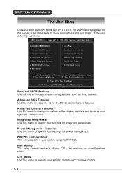
... the items of your settings for power management. Use arrow keys to move among the items and press to specify your system supports PnP/PCI. M S-7133 M -ATX M ainboard The Main Menu Once you enter AMIBIOS NEW SETUP UTILITY, the Main Menu will appear on the screen.
... the items of your settings for power management. Use arrow keys to move among the items and press to specify your system supports PnP/PCI. M S-7133 M -ATX M ainboard The Main Menu Once you enter AMIBIOS NEW SETUP UTILITY, the Main Menu will appear on the screen.
User Guide
Page 41
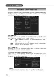
... each item: Device This item shows the information about the specified item. mon th The month from Sun to Sat, determined by BIOS. Read-only. 3-6 M S-7133 M -ATX M ainboard Standard CMOS Features The items in Standard CMOS Features Menu includes some basic setup items. Use the arrow keys to highlight the item...
... each item: Device This item shows the information about the specified item. mon th The month from Sun to Sat, determined by BIOS. Read-only. 3-6 M S-7133 M -ATX M ainboard Standard CMOS Features The items in Standard CMOS Features Menu includes some basic setup items. Use the arrow keys to highlight the item...
User Guide
Page 43
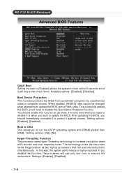
... processors that can execute instructions simultaneously. Hyper-Threading Function The processor uses Hyper-Threading technology to run the OS/2® operating system with a Flash utility. M S-7133 M -ATX M ainboard Advanced BIOS Features Quick Boot Setting the item to [Enabled] allows the system to boot within 5 seconds since it is highly improved. Settings...
... processors that can execute instructions simultaneously. Hyper-Threading Function The processor uses Hyper-Threading technology to run the OS/2® operating system with a Flash utility. M S-7133 M -ATX M ainboard Advanced BIOS Features Quick Boot Setting the item to [Enabled] allows the system to boot within 5 seconds since it is highly improved. Settings...

User Guide
Page 45
... Device" vary depending on the bootable devices you did not install a floppy drive, the setting "Floppy" will not show up. Settings are: [Yes], [No]. 3-10 MSI Reminds You... For example, if you have installed. Boot From Other Devices Setting the option to [Yes] allows the system to try to boot from... other devices if the system fails to load the operating system. M S-7133 M -ATX M ainboard Boot Sequence Press and the following sub-menu appears. 1st/2nd/3rd Boot Device These items allow you to set the sequence of...
... Device" vary depending on the bootable devices you did not install a floppy drive, the setting "Floppy" will not show up. Settings are: [Yes], [No]. 3-10 MSI Reminds You... For example, if you have installed. Boot From Other Devices Setting the option to [Yes] allows the system to try to boot from... other devices if the system fails to load the operating system. M S-7133 M -ATX M ainboard Boot Sequence Press and the following sub-menu appears. 1st/2nd/3rd Boot Device These items allow you to set the sequence of...

User Guide
Page 47
... want to enable/disable the onboard IEEE 1394 controller. Onboard LAN Controller The item enables or disables the onboard LAN controller. Setting options: [Enabled], [Disabled]. M S-7133 M -ATX M ainboard Integrated Peripherals USB Controller This setting is used to use any USB 1.1/2.0 device in the operating system that does not support or have...
... want to enable/disable the onboard IEEE 1394 controller. Onboard LAN Controller The item enables or disables the onboard LAN controller. Setting options: [Enabled], [Disabled]. M S-7133 M -ATX M ainboard Integrated Peripherals USB Controller This setting is used to use any USB 1.1/2.0 device in the operating system that does not support or have...

User Guide
Page 49
...) [SATA 1/3/2/4] [IDE1, SATA2/4] [SATA1/3, IDE1] [IDE1] 3-14 Refer to automatically determine the correct base I /O port address of the onboard parallel port. Setting options: [IRQ5], [IRQ7]. M S-7133 M -ATX M ainboard This field specifies the base I /O port address.
...) [SATA 1/3/2/4] [IDE1, SATA2/4] [SATA1/3, IDE1] [IDE1] 3-14 Refer to automatically determine the correct base I /O port address of the onboard parallel port. Setting options: [IRQ5], [IRQ7]. M S-7133 M -ATX M ainboard This field specifies the base I /O port address.