User Guide
Page 3
... for PCB 1.x Date Oct. 2002 Technical Support If a problem arises with your place of its contents. Netware® is a registered trademark of MICRO-STAR INTERNATIONAL. Revision History Revision V1.0 Revision History First release for FAQ, technical guide, BIOS updates, driver updates, and other information: http://www.msi.com.tw/ Contact our technical staff at: support@msi.com.tw iii Alternatively, please try...
... for PCB 1.x Date Oct. 2002 Technical Support If a problem arises with your place of its contents. Netware® is a registered trademark of MICRO-STAR INTERNATIONAL. Revision History Revision V1.0 Revision History First release for FAQ, technical guide, BIOS updates, driver updates, and other information: http://www.msi.com.tw/ Contact our technical staff at: support@msi.com.tw iii Alternatively, please try...
User Guide
Page 5
... Core Speed Derivation Procedure 2-3 CPU Installation Procedures for Socket 478 2-4 Installing the CPU Fan 2-5 Memory 2-7 Introduction to DDR SDRAM 2-7 Installing DDR Modules 2-8 DDR Module Combination 2-8 Power Supply 2-9 ATX 20-Pin Power Connector: CONN1 2-9 ATX 12V Power Connector: JPW1 2-9 Back Panel 2-10 Mouse Connector 2-10 Keyboard Connector 2-11 v CONTENTS FCC-B Radio Frequency Interference Statement ii Copyright Notice iii Revision History iii Technical Support iii Safety Instructions iv Chapter 1. Getting Started 1-1 Mainboard Specifications 1-2 Mainboard Layout...
... Core Speed Derivation Procedure 2-3 CPU Installation Procedures for Socket 478 2-4 Installing the CPU Fan 2-5 Memory 2-7 Introduction to DDR SDRAM 2-7 Installing DDR Modules 2-8 DDR Module Combination 2-8 Power Supply 2-9 ATX 20-Pin Power Connector: CONN1 2-9 ATX 12V Power Connector: JPW1 2-9 Back Panel 2-10 Mouse Connector 2-10 Keyboard Connector 2-11 v CONTENTS FCC-B Radio Frequency Interference Statement ii Copyright Notice iii Revision History iii Technical Support iii Safety Instructions iv Chapter 1. Getting Started 1-1 Mainboard Specifications 1-2 Mainboard Layout...

User Guide
Page 6
BIOS Setup 3-1 Entering Setup 3-2 Control Keys 3-2 Getting Help 3-3 The Main Menu 3-4 Standard CMOS Features 3-6 Advanced BIOS Features 3-8 vi Serial Port Connectors: COMA & JCOM2 (optional 2-12 RJ-45 LAN Jack (Optional 2-12 VGA Connector (optional 2-13 Audio Port Connectors 2-13 Parallel Port Connector 2-14 Connectors 2-15 Floppy Disk Drive Connectors: FDD1 2-15 Hard Disk Connectors: IDE1 & IDE2 2-16 Fan Power Connectors: CPUFAN1/SYSFAN1 2-17 CD-In Connector: CD_IN1 2-18 Aux Line-In Connector: AUX_IN1 2-18 IrDA Infrared Module Connector: IR1 2-19 Chassis Intrusion Switch ...
BIOS Setup 3-1 Entering Setup 3-2 Control Keys 3-2 Getting Help 3-3 The Main Menu 3-4 Standard CMOS Features 3-6 Advanced BIOS Features 3-8 vi Serial Port Connectors: COMA & JCOM2 (optional 2-12 RJ-45 LAN Jack (Optional 2-12 VGA Connector (optional 2-13 Audio Port Connectors 2-13 Parallel Port Connector 2-14 Connectors 2-15 Floppy Disk Drive Connectors: FDD1 2-15 Hard Disk Connectors: IDE1 & IDE2 2-16 Fan Power Connectors: CPUFAN1/SYSFAN1 2-17 CD-In Connector: CD_IN1 2-18 Aux Line-In Connector: AUX_IN1 2-18 IrDA Infrared Module Connector: IR1 2-19 Chassis Intrusion Switch ...
User Guide
Page 9
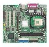
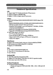
... higher speed P4 processor. h Can connect up to four IDE devices. h Intel® ICH4 chipset. (421 BGA) - h Support 533MHz or 400MHz FSB. Integrated 3D/2D graphic core (Core frequency= 200 MHz, 350 Mhz integrated 24-bit RAMDAC). - Main Memory h Support four memory banks using two 184-pin unbuffered DIMM. AC'97 Controller Integrated. - 6 ports Hi-Speed USB 2.0 controller, 480Mb/sec. - h Max memory size is 2GB without ECC (1GB/slot). KT834U5 GltrMa/2G-CLMAT/GXEMMa/PinEbMoa/GrdVM series M-ATX Mainboard Mainboard Specifications CPU h Support Intel...
... higher speed P4 processor. h Can connect up to four IDE devices. h Intel® ICH4 chipset. (421 BGA) - h Support 533MHz or 400MHz FSB. Integrated 3D/2D graphic core (Core frequency= 200 MHz, 350 Mhz integrated 24-bit RAMDAC). - Main Memory h Support four memory banks using two 184-pin unbuffered DIMM. AC'97 Controller Integrated. - 6 ports Hi-Speed USB 2.0 controller, 480Mb/sec. - h Max memory size is 2GB without ECC (1GB/slot). KT834U5 GltrMa/2G-CLMAT/GXEMMa/PinEbMoa/GrdVM series M-ATX Mainboard Mainboard Specifications CPU h Support Intel...

User Guide
Page 10
...Supports ACPI Power Management. h ACPI, SMBIOS 2.3, Green and Boot Block. Mounting h 6 mounting holes. Supports 10Mb/s and 100Mb/s auto-negotiation operation. - h 6 channels S/W audio codec (Realtek ALC 650 codec): compliant with Intel pin-definition. LAN (Optional) h PCI local bus single-chip Fast Ethernet Controller, RealTek RTL8101L. - Getting Started - 2 serial ports (COM A + JCOM2) - 1 parallel port supports SPP/EPP/ECP mode - 6 USB2.0 ports (Rear * 4 / Front * 2) - 1 Line-In/Line-Out/Mic-In port - 2 PS/2 connectors - 1 LAN RJ45 connector - 1 IrDA connector with AC97 2.1 Spec...
...Supports ACPI Power Management. h ACPI, SMBIOS 2.3, Green and Boot Block. Mounting h 6 mounting holes. Supports 10Mb/s and 100Mb/s auto-negotiation operation. - h 6 channels S/W audio codec (Realtek ALC 650 codec): compliant with Intel pin-definition. LAN (Optional) h PCI local bus single-chip Fast Ethernet Controller, RealTek RTL8101L. - Getting Started - 2 serial ports (COM A + JCOM2) - 1 parallel port supports SPP/EPP/ECP mode - 6 USB2.0 ports (Rear * 4 / Front * 2) - 1 Line-In/Line-Out/Mic-In port - 2 PS/2 connectors - 1 LAN RJ45 connector - 1 IrDA connector with AC97 2.1 Spec...
User Guide
Page 39
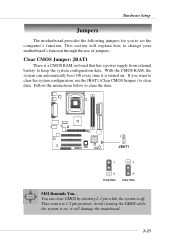
... can automatically boot OS every time it will explain how to 1-2 pin position. it is a CMOS RAM on board that has a power supply from external battery to set the computer's function. If you to keep the system configuration data. Follow the instructions below to clear data. Hardware Setup Jumpers The motherboard provides the following jumpers for you want to clear the system configuration, use of jumpers. Clear CMOS Jumper: JBAT1 There is turned on ;
... can automatically boot OS every time it will explain how to 1-2 pin position. it is a CMOS RAM on board that has a power supply from external battery to set the computer's function. If you to keep the system configuration data. Follow the instructions below to clear data. Hardware Setup Jumpers The motherboard provides the following jumpers for you want to clear the system configuration, use of jumpers. Clear CMOS Jumper: JBAT1 There is turned on ;
User Guide
Page 40
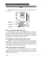
..., 32-bit channel for 845GE). AGP Slot PCI Slots CNRSlot AGP (Accelerated Graphics Port) Slot The AGP slot allows you to insert the expansion cards to insert the CNR expansion cards. CNR is done through software and controlled by the motherboard's chipset. 2-24 PCI (Peripheral Component Interconnect) Slots The PCI slots allow you to directly access main memory and provides three levels of 3D graphics. 845 GM/GLM/GEM/PEM/GVM series M-ATX Mainboard Slots The motherboard provides...
..., 32-bit channel for 845GE). AGP Slot PCI Slots CNRSlot AGP (Accelerated Graphics Port) Slot The AGP slot allows you to insert the expansion cards to insert the CNR expansion cards. CNR is done through software and controlled by the motherboard's chipset. 2-24 PCI (Peripheral Component Interconnect) Slots The PCI slots allow you to directly access main memory and provides three levels of 3D graphics. 845 GM/GLM/GEM/PEM/GVM series M-ATX Mainboard Slots The motherboard provides...
User Guide
Page 47
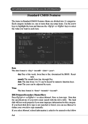
... keys. through Dec. Date The date format is . Readonly. The hard disk will not work properly if you want in Standard CMOS Features Menu are divided into 11 categories. If your drive must match with the drive table. If you can be entered to select Manual, None or Auto type. Time The time format is . 845 GM/GLM/GEM/PEM/GVM series M-ATX Mainboard Standard CMOS...
... keys. through Dec. Date The date format is . Readonly. The hard disk will not work properly if you want in Standard CMOS Features Menu are divided into 11 categories. If your drive must match with the drive table. If you can be entered to select Manual, None or Auto type. Time The time format is . 845 GM/GLM/GEM/PEM/GVM series M-ATX Mainboard Standard CMOS...

User Guide
Page 50
... the fourth HDD. MSI Reminds You... Swap Floppy Drive Setting to Enabled will swap floppy drives A: and B:. BIOS Setup CPU Hyper-Threading (for "1st/2nd/3rd Boot Device" vary depending on the bootable devices you did not install a floppy drive, the setting "Floppy" does not show up. HDD-1 The system will boot from the second HDD. ZIP The system will boot from ATAPI ZIP drive. Settings: Disabled, Enabled. 3-9 HDD-2 The system will boot from floppy drive. Boot Other Device Setting the option to Enabled allows the...
... the fourth HDD. MSI Reminds You... Swap Floppy Drive Setting to Enabled will swap floppy drives A: and B:. BIOS Setup CPU Hyper-Threading (for "1st/2nd/3rd Boot Device" vary depending on the bootable devices you did not install a floppy drive, the setting "Floppy" does not show up. HDD-1 The system will boot from the second HDD. ZIP The system will boot from ATAPI ZIP drive. Settings: Disabled, Enabled. 3-9 HDD-2 The system will boot from floppy drive. Boot Other Device Setting the option to Enabled allows the...

User Guide
Page 51
... the default value Fast is selected, the Gate A20 is implemented. A password prompt appears every time when the computer is powered on . Setting to set the rate (characters/second) at which the keys are described below: Option Setup System Description The password prompt appears only when end users try to use the arrow keys on . 845 GM/GLM/GEM/PEM/GVM series M-ATX Mainboard Boot Up...
... the default value Fast is selected, the Gate A20 is implemented. A password prompt appears every time when the computer is powered on . Setting to set the rate (characters/second) at which the keys are described below: Option Setup System Description The password prompt appears only when end users try to use the arrow keys on . 845 GM/GLM/GEM/PEM/GVM series M-ATX Mainboard Boot Up...
User Guide
Page 54
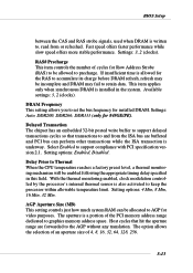
... temperature limit. With the thermal monitoring enabled, clock modulation controlled by the processor's internal thermal sensor is installed in this field. DRAM Frequency This setting allows you to precharge. Settings: Auto, DDR200, DDR266, DDR333 (only for installed DRAM. The option allows the selection of an aperture size of cycles for Row Address Strobe (RAS) to be allowed to set the bus frequency for 845GE/PE). Settings: 3, 2 (clocks). Host cycles that transactions to graphics memory...
... temperature limit. With the thermal monitoring enabled, clock modulation controlled by the processor's internal thermal sensor is installed in this field. DRAM Frequency This setting allows you to precharge. Settings: Auto, DDR200, DDR266, DDR333 (only for installed DRAM. The option allows the selection of an aperture size of cycles for Row Address Strobe (RAS) to be allowed to set the bus frequency for 845GE/PE). Settings: 3, 2 (clocks). Host cycles that transactions to graphics memory...

User Guide
Page 55
On-Chip VGA This setting allows you to use as the display(s) of the system. Settings: 1MB, 8MB Boot Display Use the field to select the type of system memory allocated for video memory. Setting options: Auto, CRT, TV, EFP. On-Chip VGA Frame Buffer Size The field specifies the size of device you want to enable or disable the on-chip VGA function.Setting: Enabled and Disabled. The option EFP refers to configure the settings about On-Chip VGA. 845 GM/GLM/GEM/PEM/GVM series M-ATX Mainboard On-Chip VGA Setting The following items allow you to the LCD display. 3-14
On-Chip VGA This setting allows you to use as the display(s) of the system. Settings: 1MB, 8MB Boot Display Use the field to select the type of system memory allocated for video memory. Setting options: Auto, CRT, TV, EFP. On-Chip VGA Frame Buffer Size The field specifies the size of device you want to enable or disable the on-chip VGA function.Setting: Enabled and Disabled. The option EFP refers to configure the settings about On-Chip VGA. 845 GM/GLM/GEM/PEM/GVM series M-ATX Mainboard On-Chip VGA Setting The following items allow you to the LCD display. 3-14
User Guide
Page 56
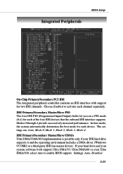
Choose Enabled to enable BIOS support. Settings: Auto, Disabled. 3-15 Modes 0 through 4 provide successively increased performance. If your hard drive and your IDE hard drive supports it and the operating environment includes a DMA driver (Windows 95 OSR2 or a third-party IDE bus master driver). IDE Primary/Secondary Master/Slave UDMA Ultra DMA/33/66/100 implementation is possible only if your system software both support Ultra DMA/33, Ultra DMA/66 or even...
Choose Enabled to enable BIOS support. Settings: Auto, Disabled. 3-15 Modes 0 through 4 provide successively increased performance. If your hard drive and your IDE hard drive supports it and the operating environment includes a DMA driver (Windows 95 OSR2 or a third-party IDE bus master driver). IDE Primary/Secondary Master/Slave UDMA Ultra DMA/33/66/100 implementation is possible only if your system software both support Ultra DMA/33, Ultra DMA/66 or even...
User Guide
Page 57
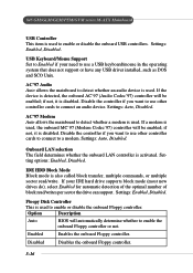
... Enabled Enables the onboard Floppy controller. Settings: Enabled, Disabled. Disable the controller if you want to use other controller cards to detect whether an audio device is used. If your need to enable or disable the onboard USB controllers. 845 GM/GLM/GEM/PEM/GVM series M-ATX Mainboard USB Controller This item is used to use a USB keyboard/mouse in the operating system that does not support or have any USB driver installed, such as DOS and SCO Unix. Setting options: Enabled, Disabled. USB Keyboard/Mouse Support Set to Enabled if your IDE hard drive supports block mode...
... Enabled Enables the onboard Floppy controller. Settings: Enabled, Disabled. Disable the controller if you want to use other controller cards to detect whether an audio device is used. If your need to enable or disable the onboard USB controllers. 845 GM/GLM/GEM/PEM/GVM series M-ATX Mainboard USB Controller This item is used to use a USB keyboard/mouse in the operating system that does not support or have any USB driver installed, such as DOS and SCO Unix. Setting options: Enabled, Disabled. USB Keyboard/Mouse Support Set to Enabled if your IDE hard drive supports block mode...
User Guide
Page 64
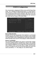
... experienced users should make any changes to "manual" choose specific resources by a "¾"). The settings are using a Plug and Play operating system such as Windows 95/98. The settings are: Auto (ESCD), Manual. 3-23 PCI, or Peripheral Component Interconnect, is strongly recommended that follows this field (a sub menu is preceded by going into each of the boot and Plug and Play compatible devices. Select Enabled to reset Extended System Configuration...
... experienced users should make any changes to "manual" choose specific resources by a "¾"). The settings are using a Plug and Play operating system such as Windows 95/98. The settings are: Auto (ESCD), Manual. 3-23 PCI, or Peripheral Component Interconnect, is strongly recommended that follows this field (a sub menu is preceded by going into each of the boot and Plug and Play compatible devices. Select Enabled to reset Extended System Configuration...
User Guide
Page 66
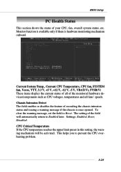
... is once opened. To clear the warning message, set the field to prevent the CPU overheating problem. 3-25 This helps you to Reset. Chassis Intrusion Detect The field enables or disables the feature of the monitored hardware devices/components such as CPU voltages, temperatures and all fans' speeds. Current System Temp., Current CPU Temperature, CPU fan, SYSTEM fan, Vcore, VTT, 3.3 V, +5 V, +12 V, -12 V, -5 V, VBAT(V), 5VSB(V) These items display the current status of...
... is once opened. To clear the warning message, set the field to prevent the CPU overheating problem. 3-25 This helps you to Reset. Chassis Intrusion Detect The field enables or disables the feature of the monitored hardware devices/components such as CPU voltages, temperatures and all fans' speeds. Current System Temp., Current CPU Temperature, CPU fan, SYSTEM fan, Vcore, VTT, 3.3 V, +5 V, +12 V, -12 V, -5 V, VBAT(V), 5VSB(V) These items display the current status of...

User Guide
Page 71
...-66 or ATA100 HDD, but says an error saying "Primary IDE Channel no 80 Conductor Cable Installed" A: This is printed circuit board. You can find MS-xxxx or the marketing name like Taisol CGK760092, Vantec CCK6035D & GlobalWin WBK38. A: PCB is not a problem. T-1 Troubleshooting Troubleshooting Troubleshooting Q: Where will I have got MSI Motherboard and when it says detecting drives, it . 2. Somewhere between the PCI slots you mean ? Q: How...
...-66 or ATA100 HDD, but says an error saying "Primary IDE Channel no 80 Conductor Cable Installed" A: This is printed circuit board. You can find MS-xxxx or the marketing name like Taisol CGK760092, Vantec CCK6035D & GlobalWin WBK38. A: PCB is not a problem. T-1 Troubleshooting Troubleshooting Troubleshooting Q: Where will I have got MSI Motherboard and when it says detecting drives, it . 2. Somewhere between the PCI slots you mean ? Q: How...

User Guide
Page 75
... fully support ACPI to allow users managing the system power flexibly. Glossary Glossary Glossary ACPI (Advanced Configuration & Power Interface) This power management specification enables the OS (operating system) to control the amount of the technology). AGP provides a direct channel (32-bit wide bus) between two devices. Bluetooth Bluetooth refers to a worldwide standard for the wireless exchange of input/output interface (such as keyboard, disk drives, etc.). It stores the G-1 Windows...
... fully support ACPI to allow users managing the system power flexibly. Glossary Glossary Glossary ACPI (Advanced Configuration & Power Interface) This power management specification enables the OS (operating system) to control the amount of the technology). AGP provides a direct channel (32-bit wide bus) between two devices. Bluetooth Bluetooth refers to a worldwide standard for the wireless exchange of input/output interface (such as keyboard, disk drives, etc.). It stores the G-1 Windows...
User Guide
Page 78
... microprocessor. The IDE interface is also called the primary cache. Internal Cache Short for transmitting data via infrared light waves. IRQ (Interrupt Request Line) IRQs are connected by setting a DIP switch. It allows 16 bits at a time to flow between the motherboard circuitry and an expansion slot card and its IRQ number by cables to access data and devices anywhere on the LAN, so that...
... microprocessor. The IDE interface is also called the primary cache. Internal Cache Short for transmitting data via infrared light waves. IRQ (Interrupt Request Line) IRQs are connected by setting a DIP switch. It allows 16 bits at a time to flow between the motherboard circuitry and an expansion slot card and its IRQ number by cables to access data and devices anywhere on the LAN, so that...
User Guide
Page 79
... a time. LED (Light Emitting Diode) A semiconductor device that supports PnP and a PnP expansion card are properly connected and operating. To implement this useful feature, both the BIOS that converts electrical energy into light. PnP (Plug and Play) A set of specifications that allows a PC to configure itself automatically to address a hard disk larger than the manufacturer-specified speed (for up to the computer bus or data paths. PCI (Peripheral...
... a time. LED (Light Emitting Diode) A semiconductor device that supports PnP and a PnP expansion card are properly connected and operating. To implement this useful feature, both the BIOS that converts electrical energy into light. PnP (Plug and Play) A set of specifications that allows a PC to configure itself automatically to address a hard disk larger than the manufacturer-specified speed (for up to the computer bus or data paths. PCI (Peripheral...


