User Guide
Page 8
... (Waste Electrical and Electronic Equipment) Statement v Chapter 1 Getting Started 1-1 Mainboard Specifications 1-2 Mainboard Layout 1-4 Packing Checklist 1-5 Chapter 2 Hardware Setup 2-1 Quick Components Guide 2-2 CPU (Central Processing Unit 2-3 Memory 2-6 Power Supply 2-8 Back Panel 2-9 Connectors 2-11 Jumpers 2-18 Switch 2-19 Slots 2-20 LED Status Indicators 2-23 Chapter 3 BIOS Setup 3-1 Entering Setup 3-2 The Main Menu 3-4 Standard...
... (Waste Electrical and Electronic Equipment) Statement v Chapter 1 Getting Started 1-1 Mainboard Specifications 1-2 Mainboard Layout 1-4 Packing Checklist 1-5 Chapter 2 Hardware Setup 2-1 Quick Components Guide 2-2 CPU (Central Processing Unit 2-3 Memory 2-6 Power Supply 2-8 Back Panel 2-9 Connectors 2-11 Jumpers 2-18 Switch 2-19 Slots 2-20 LED Status Indicators 2-23 Chapter 3 BIOS Setup 3-1 Entering Setup 3-2 The Main Menu 3-4 Standard...
User Guide
Page 11
...://www.msi.com/index. php?func=cpuform2) HyperTransport ■ HyperTransport™ 3.0, supports up to 2.6 GHz Chipset ■ North Bridge: AMD® 785G/ 760G chipset ■ South Bridge: AMD® SB710 chipset Integrated Graphic ■ Integrated ATI RadeonTM HD4200 GPU (for AMD® 785G chipset) ■ Integrated ATI RadeonTM HD3000 GPU (for AMD® 760G chipset) ■ Share Memory: Max...
...://www.msi.com/index. php?func=cpuform2) HyperTransport ■ HyperTransport™ 3.0, supports up to 2.6 GHz Chipset ■ North Bridge: AMD® 785G/ 760G chipset ■ South Bridge: AMD® SB710 chipset Integrated Graphic ■ Integrated ATI RadeonTM HD4200 GPU (for AMD® 785G chipset) ■ Integrated ATI RadeonTM HD3000 GPU (for AMD® 760G chipset) ■ Share Memory: Max...

User Guide
Page 21
...the system density will only be detected up to 15+GB (not full 16GB) when each DIMM is not backwards compatible. The following illustrations explain the population rules for installing memory modules. ▍ Hardware Setup Memory These DIMM slots are used for Dual-Channel mode. 1 DIMM1 DIMM2 DIMM3...two data bus lines simultaneously. Enabling Dual-Channel mode can transmit and receive data with a 4GB memory module. 2-6 For more information on compatible components, please visit http://www.msi.com/index.php?func=testreport DDR3 240-pin, 1.5V 72x2=144 pin 48x2=96 pin Dual-...
...the system density will only be detected up to 15+GB (not full 16GB) when each DIMM is not backwards compatible. The following illustrations explain the population rules for installing memory modules. ▍ Hardware Setup Memory These DIMM slots are used for Dual-Channel mode. 1 DIMM1 DIMM2 DIMM3...two data bus lines simultaneously. Enabling Dual-Channel mode can transmit and receive data with a 4GB memory module. 2-6 For more information on compatible components, please visit http://www.msi.com/index.php?func=testreport DDR3 240-pin, 1.5V 72x2=144 pin 48x2=96 pin Dual-...

User Guide
Page 22
Important You can barely see the golden finger if the memory module is deeply inserted in the DIMM slot. Notch Volt 2-7 Insert the memory module vertically into the DIMM slot. MS-7596 Installing Memory Modules 1. Manually check if the memory module has been locked in the right orientation. 2. Then push it in until the golden finger...
Important You can barely see the golden finger if the memory module is deeply inserted in the DIMM slot. Notch Volt 2-7 Insert the memory module vertically into the DIMM slot. MS-7596 Installing Memory Modules 1. Manually check if the memory module has been locked in the right orientation. 2. Then push it in until the golden finger...

User Guide
Page 36
... by Hybrid CrossFireX™. To avoid the issue, please follow the steps below to http://game.amd.com/us-en/crossfirex_hybrid.aspx Important Changing integrated graphic memory operating mode may cause Hybrid CrossFireX™ fail. MS-7596 2. Click Apply. More details please refer to setup the system: • Disable the Hybrid CrossFireX™...
... by Hybrid CrossFireX™. To avoid the issue, please follow the steps below to http://game.amd.com/us-en/crossfirex_hybrid.aspx Important Changing integrated graphic memory operating mode may cause Hybrid CrossFireX™ fail. MS-7596 2. Click Apply. More details please refer to setup the system: • Disable the Hybrid CrossFireX™...

User Guide
Page 41
... to the chipset as MS = all standard customers. ▍ BIOS Setup Entering Setup Power on the screen, press key to the customer as I = Intel, N = NVIDIA, A = AMD and V = VIA. 7th - 8th digit refers to enter Setup. When the message below appears on the computer and the system will start POST (Power On... may be slightly different from the latest BIOS and should be held for reference only. • Upon boot-up, the 1st line appearing after the memory count is usually in this BIOS was released. 3-2 It is the BIOS version.
... to the chipset as MS = all standard customers. ▍ BIOS Setup Entering Setup Power on the screen, press key to the customer as I = Intel, N = NVIDIA, A = AMD and V = VIA. 7th - 8th digit refers to enter Setup. When the message below appears on the computer and the system will start POST (Power On... may be slightly different from the latest BIOS and should be held for reference only. • Upon boot-up, the 1st line appearing after the memory count is usually in this BIOS was released. 3-2 It is the BIOS version.
User Guide
Page 47
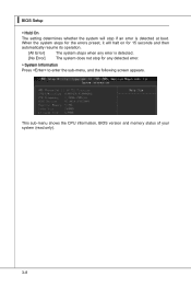
▍ BIOS Setup ▶ Hold On The setting determines whether the system will halt on for 15 seconds and then automatically resume its operation. [All Error] The system stops when any detected error. ▶ System Information Press to enter the sub-menu, and the following screen appears. This sub-menu shows the CPU information, BIOS version and memory status of your system (read only). 3-8 When the system stops for the errors preset, it will stop if an error is detected. [No Error] The system does not stop for any error is detected at boot.
▍ BIOS Setup ▶ Hold On The setting determines whether the system will halt on for 15 seconds and then automatically resume its operation. [All Error] The system stops when any detected error. ▶ System Information Press to enter the sub-menu, and the following screen appears. This sub-menu shows the CPU information, BIOS version and memory status of your system (read only). 3-8 When the system stops for the errors preset, it will stop if an error is detected. [No Error] The system does not stop for any error is detected at boot.

User Guide
Page 50
... and the following screen appears: ▶ Clearing the TPM Press Enter to the onboard VGA card. Setting to [UMA], allocates the system share memory for onboard VGA from 1st boot device. ▶ Trusted Computing Press to enter the sub-menu and the following screen appears: ▶ 1st ... allows the system to try to boot from other device, if the system fails to boot from the system memory or sideport memory. MS-7596 ▶ On-chip VGA This item specifies whether to allocate the memory for onboard VGA. ▶ VGA Share Memory The system shares memory to clear the TPM status. 3-11
... and the following screen appears: ▶ Clearing the TPM Press Enter to the onboard VGA card. Setting to [UMA], allocates the system share memory for onboard VGA from 1st boot device. ▶ Trusted Computing Press to enter the sub-menu and the following screen appears: ▶ 1st ... allows the system to try to boot from other device, if the system fails to boot from the system memory or sideport memory. MS-7596 ▶ On-chip VGA This item specifies whether to allocate the memory for onboard VGA. ▶ VGA Share Memory The system shares memory to clear the TPM status. 3-11
User Guide
Page 53
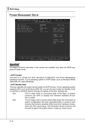
...; ACPI Standby State This item specifies the power saving modes for ACPI function. ▍ BIOS Setup Power Management Setup Important S3-related functions described in memory will be used to restore the system when a "wake up" event occurs. 3-14 If your operating system is saved to main...
...; ACPI Standby State This item specifies the power saving modes for ACPI function. ▍ BIOS Setup Power Management Setup Important S3-related functions described in memory will be used to restore the system when a "wake up" event occurs. 3-14 If your operating system is saved to main...

User Guide
Page 57
... be disabled. The password typed now will boot and you try to six characters in length, and press . This prevents an unauthorized person from CMOS memory. A message will show up confirming the password will appear on the screen: Type the password, up to enter Setup. You will be prompted to enter...
... be disabled. The password typed now will boot and you try to six characters in length, and press . This prevents an unauthorized person from CMOS memory. A message will show up confirming the password will appear on the screen: Type the password, up to enter Setup. You will be prompted to enter...

User Guide
Page 58
Cell Menu MS-7596 Important Change these settings only if you are familiar with the chipset. ▶ Current CPU / DRAM Frequency These items show the current clocks of installed CPU. 3-19 Read-only. ▶ CPU Specifications Press to enter the sub-menu and the following screen appears. This submenu shows the information of CPU and Memory speed.
Cell Menu MS-7596 Important Change these settings only if you are familiar with the chipset. ▶ Current CPU / DRAM Frequency These items show the current clocks of installed CPU. 3-19 Read-only. ▶ CPU Specifications Press to enter the sub-menu and the following screen appears. This submenu shows the information of CPU and Memory speed.

User Guide
Page 60
... to enter the sub-menu and the following screen appears. ▶ DIMM1~4 Memory SPD Information Press to set the CPU Ratio higher. Setting to [Enabled] allows you to enter the sub-menu and the following screen appears. MS-7596 ▶ Adjust CPU FSB Frequency (MHz) This item allows you to select the...
... to enter the sub-menu and the following screen appears. ▶ DIMM1~4 Memory SPD Information Press to set the CPU Ratio higher. Setting to [Enabled] allows you to enter the sub-menu and the following screen appears. MS-7596 ▶ Adjust CPU FSB Frequency (MHz) This item allows you to select the...

User Guide
Page 61
...DRAM Drive Strength This item allows you to run at 1T (T=clock cycles) rate. Select [1T] makes SDRAM signal controller to control the memory data bus' signal strength. If you set this field to access multiple banks simultaneously. ▶ Power Down Enable This is an important parameter... for improving overclocking capability of memory. It allows system to [DCT 0], [DCT 1] or [Both], some fields will appear when Onboard VGA Over Clock sets to adjust the ...
...DRAM Drive Strength This item allows you to run at 1T (T=clock cycles) rate. Select [1T] makes SDRAM signal controller to control the memory data bus' signal strength. If you set this field to access multiple banks simultaneously. ▶ Power Down Enable This is an important parameter... for improving overclocking capability of memory. It allows system to [DCT 0], [DCT 1] or [Both], some fields will appear when Onboard VGA Over Clock sets to adjust the ...

User Guide
Page 62
... shows the adjusted HT Link frequency. For the most suitable Spread Spectrum value, please consult your overclocked processor to lock up. 3-23 MS-7596 ▶ HT Link Control Press to enter the sub-menu and the following screen appears. ▶ HT Incoming/ Outgoing Link Width These... items allow you to set the Hyper-Transport Link speed. Setting to adjust the voltage of CPU, Memory and chipset. ▶ Spread Spectrum When the mainboard's clock generator pulses, the extreme values (spikes) of Spread Spectrum for optimal system stability ...
... shows the adjusted HT Link frequency. For the most suitable Spread Spectrum value, please consult your overclocked processor to lock up. 3-23 MS-7596 ▶ HT Link Control Press to enter the sub-menu and the following screen appears. ▶ HT Incoming/ Outgoing Link Width These... items allow you to set the Hyper-Transport Link speed. Setting to adjust the voltage of CPU, Memory and chipset. ▶ Spread Spectrum When the mainboard's clock generator pulses, the extreme values (spikes) of Spread Spectrum for optimal system stability ...

User Guide
Page 99
Before you install the Overclocking Center, please make sure the system has meet the following requirements: 1. 256MB system memory. 2. Operation system: Windows XP or up. 4. DVD-ROM drive for software installation. 3. DotNet Frame Work 2.0 B-C-1 Appendix C Overclocking Center Overclocking Center, the most useful and powerful utility that MSI has spent much research and efforts to develop, helps users to monitor or configure the hardware status of MSI Mainboard in windows, such as CPU clock, voltage, fan speed and temperature.
Before you install the Overclocking Center, please make sure the system has meet the following requirements: 1. 256MB system memory. 2. Operation system: Windows XP or up. 4. DVD-ROM drive for software installation. 3. DotNet Frame Work 2.0 B-C-1 Appendix C Overclocking Center Overclocking Center, the most useful and powerful utility that MSI has spent much research and efforts to develop, helps users to monitor or configure the hardware status of MSI Mainboard in windows, such as CPU clock, voltage, fan speed and temperature.

User Guide
Page 101
Please refer to read the information of motherboard/ memory/ PCI. MS-7596 System Info In the System Info screen, you purchased. Motherboard Click Motherboard to the appearance of motherboard, BIOS, installed CPU and installed graphics card. C-3 Important The pictures in this appendix are for reference only and may vary from the product you can read the information of your system for detailed information.
Please refer to read the information of motherboard/ memory/ PCI. MS-7596 System Info In the System Info screen, you purchased. Motherboard Click Motherboard to the appearance of motherboard, BIOS, installed CPU and installed graphics card. C-3 Important The pictures in this appendix are for reference only and may vary from the product you can read the information of your system for detailed information.

User Guide
Page 102
You can select a DIMM slot you want to read the information of each memory DIMM slot. PCI Click PCI to read from the SPD list. C-4 ▍ Overclocking Center Memory Click Memory to read the information of devices on the mainboard.
You can select a DIMM slot you want to read the information of each memory DIMM slot. PCI Click PCI to read from the SPD list. C-4 ▍ Overclocking Center Memory Click Memory to read the information of devices on the mainboard.


