
User Guide
Page 3
MS-7596 Safety Instructions ■ Always read the safety instructions carefully. ■ Keep this User's Manual for future reference. ■ Keep this equipment away from overheating. DO ...
MS-7596 Safety Instructions ■ Always read the safety instructions carefully. ■ Keep this User's Manual for future reference. ■ Keep this equipment away from overheating. DO ...

User Guide
Page 4
... encouraged to try to correct the interference by the party responsible for a Class B digital device, pursuant to Part 15 of the FCC Rules. Micro-Star International MS-7596 This device complies with the emission limits. VOIR LA NOTICE D'INSTALLATION AVANT DE RACCORDER AU RESEAU. power cord, if any, must accept any interference...
... encouraged to try to correct the interference by the party responsible for a Class B digital device, pursuant to Part 15 of the FCC Rules. Micro-Star International MS-7596 This device complies with the emission limits. VOIR LA NOTICE D'INSTALLATION AVANT DE RACCORDER AU RESEAU. power cord, if any, must accept any interference...

User Guide
Page 5
MS-7596 WEEE (Waste Electrical and Electronic Equipment) Statement ENGLISH To protect the global ...dans les points de collecte. You can return these products to take back requirements at the end of MSI-branded products that ... MSI hat europaweit verschiedene Sammel- Les fabricants de ces équipements seront obligés de récupé... which takes effect on August 13, 2005, products of "electrical and electronic equipment" cannot be discarded as an environmentalist, MSI must remind you that are sold into the EU. Au sujet de la directive européenne (EU) relative aux...
MS-7596 WEEE (Waste Electrical and Electronic Equipment) Statement ENGLISH To protect the global ...dans les points de collecte. You can return these products to take back requirements at the end of MSI-branded products that ... MSI hat europaweit verschiedene Sammel- Les fabricants de ces équipements seront obligés de récupé... which takes effect on August 13, 2005, products of "electrical and electronic equipment" cannot be discarded as an environmentalist, MSI must remind you that are sold into the EU. Au sujet de la directive européenne (EU) relative aux...

User Guide
Page 9
MS-7596 User Settings 3-27 Load Fail-Safe/ Optimized Defaults 3-28 Appendix A Realtek Audio A-1 Installing the Realtek HD Audio Driver A-2 Software Configuration A-4 Hardware Setup A-19 Appendix B SB710 RAID B-1 RAID Configuration B-2 Appendix C Overclocking Center C-1 Activating Overclocking Center C-2 System Info C-3 DOT C-5 ix
MS-7596 User Settings 3-27 Load Fail-Safe/ Optimized Defaults 3-28 Appendix A Realtek Audio A-1 Installing the Realtek HD Audio Driver A-2 Software Configuration A-4 Hardware Setup A-19 Appendix B SB710 RAID B-1 RAID Configuration B-2 Appendix C Overclocking Center C-1 Activating Overclocking Center C-2 System Info C-3 DOT C-5 ix

User Guide
Page 10
The 785GM-E51/ 760GM-E51 Series mainboards are based on AMD® 785G/ 760G & SB710 chipsets for choosing the 785GM-E51/ 760GM-E51 Series (MS-7596 v1.X) Micro ATX mainboard. Designed to fit the advanced AMD® 64 bits PhenomTM II processor, the 785GM-E51/ 760GME51 Series deliver a high performance and professional desktop platform solution. 1-1-1 Chapter 1 Getting Started Thank you for optimal system efficiency.
The 785GM-E51/ 760GM-E51 Series mainboards are based on AMD® 785G/ 760G & SB710 chipsets for choosing the 785GM-E51/ 760GM-E51 Series (MS-7596 v1.X) Micro ATX mainboard. Designed to fit the advanced AMD® 64 bits PhenomTM II processor, the 785GM-E51/ 760GME51 Series deliver a high performance and professional desktop platform solution. 1-1-1 Chapter 1 Getting Started Thank you for optimal system efficiency.

User Guide
Page 12
... Gen2 x16 slot ■ 1 PCI Express x1 slot ■ 2 PCI slots, support 3.3V/ 5V PCI bus Interface Form Factor ■ Micro-ATX (24.4cm X 24.4 cm) Mounting ■ 8 mounting holes MS-7596 If you need to purchase accessories and request the part numbers, you could search the product web page and find details...
... Gen2 x16 slot ■ 1 PCI Express x1 slot ■ 2 PCI slots, support 3.3V/ 5V PCI bus Interface Form Factor ■ Micro-ATX (24.4cm X 24.4 cm) Mounting ■ 8 mounting holes MS-7596 If you need to purchase accessories and request the part numbers, you could search the product web page and find details...

User Guide
Page 13
▍ Getting Started Mainboard Layout 785GM-E51/ 760GM-E51 Series (MS-7596 v1.X) Mainboard 1-4
▍ Getting Started Mainboard Layout 785GM-E51/ 760GM-E51 Series (MS-7596 v1.X) Mainboard 1-4

User Guide
Page 14
Packing Checklist MS-7596 MSI mainboard MSI Driver/Utility DVD SATA Cable (Optional) Power Cable USB Bracket (Optional) Standard Cable for IDE Devices Back IO Shield User's Guide * The pictures are for reference only and may vary from the packing contents of the product you could search the product web page and find details on our web address http://www.msi.com/index.php 1-5 If you need to purchase accessories and request the part numbers, you purchased.
Packing Checklist MS-7596 MSI mainboard MSI Driver/Utility DVD SATA Cable (Optional) Power Cable USB Bracket (Optional) Standard Cable for IDE Devices Back IO Shield User's Guide * The pictures are for reference only and may vary from the packing contents of the product you could search the product web page and find details on our web address http://www.msi.com/index.php 1-5 If you need to purchase accessories and request the part numbers, you purchased.

User Guide
Page 18
... However, please make sure to install the cooler to prevent overheating. Replacing the CPU While replacing the CPU, always turn off the ATX power supply or unplug the power supply's power cord from overheating. We do not have the CPU cooler, consult your components are ... that you do not guarantee the damages or risks caused by inadequate operation or beyond product specifications is designed to support overclocking. MS-7596 CPU (Central Processing Unit) When you are able to tolerate such abnormal setting, while doing overclocking. For the latest information about CPU...
... However, please make sure to install the cooler to prevent overheating. Replacing the CPU While replacing the CPU, always turn off the ATX power supply or unplug the power supply's power cord from overheating. We do not have the CPU cooler, consult your components are ... that you do not guarantee the damages or risks caused by inadequate operation or beyond product specifications is designed to support overclocking. MS-7596 CPU (Central Processing Unit) When you are able to tolerate such abnormal setting, while doing overclocking. For the latest information about CPU...

User Guide
Page 20
... CPU Fan cable to fasten the cooling set onto the retention mechanism. The appearance of the clip to keep an eye on the mainboard. MS-7596 5. Then press down the lever. 8. Hook one end of your fingers, because once the Safety Hook is necessary to hook first. 6.
... CPU Fan cable to fasten the cooling set onto the retention mechanism. The appearance of the clip to keep an eye on the mainboard. MS-7596 5. Then press down the lever. 8. Hook one end of your fingers, because once the Safety Hook is necessary to hook first. 6.

User Guide
Page 22
The plastic clip at the sides. Notch Volt 2-7 MS-7596 Installing Memory Modules 1. Then push it in the DIMM slot. Important You can barely see the golden finger if the memory module is properly seated. 3. ...
The plastic clip at the sides. Notch Volt 2-7 MS-7596 Installing Memory Modules 1. Then push it in the DIMM slot. Important You can barely see the golden finger if the memory module is properly seated. 3. ...
User Guide
Page 24
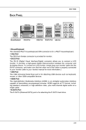
... of transmitting uncompressed streams. HDMI supports all -digital audio/video interface capable of the cable is for attaching the E-SATA hard drive. 2-9 Back Panel MS-7596 VGA Port Mouse/Keyboard DVI-D Port USB Port LAN USB Port USB Port HDMI Port E-SATA Port USB Port Line-In RS-Out Line-Out...
... of transmitting uncompressed streams. HDMI supports all -digital audio/video interface capable of the cable is for attaching the E-SATA hard drive. 2-9 Back Panel MS-7596 VGA Port Mouse/Keyboard DVI-D Port USB Port LAN USB Port USB Port HDMI Port E-SATA Port USB Port Line-In RS-Out Line-Out...
User Guide
Page 26
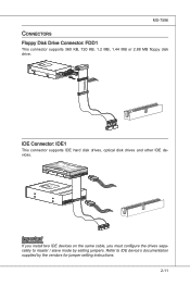
... If you install two IDE devices on the same cable, you must configure the drives separately to IDE device's documentation supplied by setting jumpers. MS-7596 Connectors Floppy Disk Drive Connector: FDD1 This connector supports 360 KB, 720 KB, 1.2 MB, 1.44 MB or 2.88 MB floppy disk drive. Refer to master...
... If you install two IDE devices on the same cable, you must configure the drives separately to IDE device's documentation supplied by setting jumpers. MS-7596 Connectors Floppy Disk Drive Connector: FDD1 This connector supports 360 KB, 720 KB, 1.2 MB, 1.44 MB or 2.88 MB floppy disk drive. Refer to master...
User Guide
Page 28
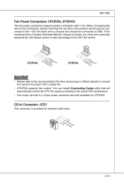
... supports fan control. CD-In Connector: JCD1 This connector is the positive and should be connected to take advantage of the CPU fan control. MS-7596 Fan Power Connectors: CPUFAN, SYSFAN The fan power connectors support system cooling fan with +12V.
... supports fan control. CD-In Connector: JCD1 This connector is the positive and should be connected to take advantage of the CPU fan control. MS-7596 Fan Power Connectors: CPUFAN, SYSFAN The fan power connectors support system cooling fan with +12V.

User Guide
Page 30
....U7BS.DG9B-.rNDoo+unPdin USB 2.0 Bracket (optional) Important Note that the pins of VCC and GND must be connected correctly to avoid possible damage. MS-7596 Front USB Connector: JUSB1 / JUSB2 / JUSB3 This connector, compliant with Intel® I/O Connectivity Design Guide, is compliant with Intel® Front Panel I/O Connectivity Design Guide...
....U7BS.DG9B-.rNDoo+unPdin USB 2.0 Bracket (optional) Important Note that the pins of VCC and GND must be connected correctly to avoid possible damage. MS-7596 Front USB Connector: JUSB1 / JUSB2 / JUSB3 This connector, compliant with Intel® I/O Connectivity Design Guide, is compliant with Intel® Front Panel I/O Connectivity Design Guide...

User Guide
Page 32
MS-7596 TPM Module connector: JTPM1 This connector connects to the TPM security platform manual for more details and usages. 2.34V.36S..3tS8aVe.n15Prd0iVaob1.NlwyP2I1o.eRopG4rwoPQ.rwGeionreurornudnd 1.L3P.L5CP.LCC7P.loLRC9cP.eLka1CsPd1e1ad.CtL3drPea.dLsdCrPsedasCr&edsFdsd&sraraedt&amsasdpteaa&intpa0dinap1tian2pin3 2-17 Please refer to a TPM (Trusted Platform Module) module (optional).
MS-7596 TPM Module connector: JTPM1 This connector connects to the TPM security platform manual for more details and usages. 2.34V.36S..3tS8aVe.n15Prd0iVaob1.NlwyP2I1o.eRopG4rwoPQ.rwGeionreurornudnd 1.L3P.L5CP.LCC7P.loLRC9cP.eLka1CsPd1e1ad.CtL3drPea.dLsdCrPsedasCr&edsFdsd&sraraedt&amsasdpteaa&intpa0dinap1tian2pin3 2-17 Please refer to a TPM (Trusted Platform Module) module (optional).

User Guide
Page 34
... of FSB Increase 20% speed of switch. Follow the instructions below to set the switch to increase the processor frequency by changing the switch. MS-7596 Switch This mainboard provides the following switch for you power off the system before setting the switch. • When overclocking cause system instability or crash...
... of FSB Increase 20% speed of switch. Follow the instructions below to set the switch to increase the processor frequency by changing the switch. MS-7596 Switch This mainboard provides the following switch for you power off the system before setting the switch. • When overclocking cause system instability or crash...

User Guide
Page 36
MS-7596 2. To avoid the issue, please follow the steps below to http://game.amd.com/us-en/crossfirex_hybrid.aspx Important Changing integrated graphic memory operating mode may cause Hybrid CrossFireX™ fail. Select "Enable CrossFire™". 5. More details please ...
MS-7596 2. To avoid the issue, please follow the steps below to http://game.amd.com/us-en/crossfirex_hybrid.aspx Important Changing integrated graphic memory operating mode may cause Hybrid CrossFireX™ fail. Select "Enable CrossFire™". 5. More details please ...

User Guide
Page 38
CPU is in 4 phase power mode. 2-23 Blue light Off LED1 LED2 LED3 LED4 Mode CPU is in 1 phase power mode. Follow the instructions below to read. LED Status Indicators MS-7596 CPU Phase LEDs: LED1, LED2, LED3, LED4 These LEDs indicate the current CPU power phase mode.
CPU is in 4 phase power mode. 2-23 Blue light Off LED1 LED2 LED3 LED4 Mode CPU is in 1 phase power mode. Follow the instructions below to read. LED Status Indicators MS-7596 CPU Phase LEDs: LED1, LED2, LED3, LED4 These LEDs indicate the current CPU power phase mode.
User Guide
Page 42
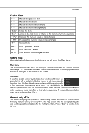
... item in the left of certain fields that means a sub-menu can be launched from this screen from field to field within a sub-menu. MS-7596 Control Keys Move to the previous item Move to the next item Move to the item in the right hand Select the item Jumps to...
... item in the left of certain fields that means a sub-menu can be launched from this screen from field to field within a sub-menu. MS-7596 Control Keys Move to the previous item Move to the next item Move to the item in the right hand Select the item Jumps to...