User Guide
Page 3
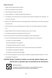
... flat surface before setting it . The equipment has been exposed to the power inlet. 7. CAUTION: Danger of explosion if battery is damaged. - Do not cover the openings. 6. Make sure the voltage of the power source and adjust properly 110/220V before inserting any of breakage. 12. Safety Instructions 1. The power cord or plug is incorrectly replaced. Liquid has penetrated...
... flat surface before setting it . The equipment has been exposed to the power inlet. 7. CAUTION: Danger of explosion if battery is damaged. - Do not cover the openings. 6. Make sure the voltage of the power source and adjust properly 110/220V before inserting any of breakage. 12. Safety Instructions 1. The power cord or plug is incorrectly replaced. Liquid has penetrated...
User Guide
Page 5
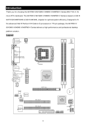
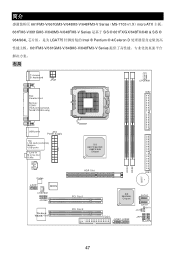
....X) micro ATX mainboard. Ou t B:Mic SiS 661FX/661GX/ 648FX/648 Chipset CD_IN1 DDR1 DDR2 BAT T + Codec JAUD1 BIOS CH SFAN 1 JCOM2 Winbond W 83 6 8 7 T H F AGP Slot IDE1 PCI Slot 1 PCI Slot 2 SiS 964/964L Chipset SATA2 SATA1 JCI1 JB AT1 FDD1 JUSB1 JUSB2 JF P1 JFP2 1 In M :L i ne - Layout T: mouse B: keyboard JPW1 C PUFAN 1 IDE2 AT X Power Supply T: L in 775 pin package, the 661FM3-V/ 661GM3-V/648M3-V/648FM3-V Series delivers a high performance...
....X) micro ATX mainboard. Ou t B:Mic SiS 661FX/661GX/ 648FX/648 Chipset CD_IN1 DDR1 DDR2 BAT T + Codec JAUD1 BIOS CH SFAN 1 JCOM2 Winbond W 83 6 8 7 T H F AGP Slot IDE1 PCI Slot 1 PCI Slot 2 SiS 964/964L Chipset SATA2 SATA1 JCI1 JB AT1 FDD1 JUSB1 JUSB2 JF P1 JFP2 1 In M :L i ne - Layout T: mouse B: keyboard JPW1 C PUFAN 1 IDE2 AT X Power Supply T: L in 775 pin package, the 661FM3-V/ 661GM3-V/648M3-V/648FM3-V Series delivers a high performance...

User Guide
Page 6
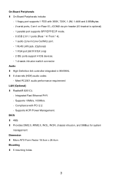
...) 2 High Definition Audio interface - 8 USB 2.0/1.1 ports - 2 channel Ultra ATA66/100/133 Bus Master IDE controller - 2 serial ATA Host Controllers (964 only) Main Memory l Supports 64-bit wide DDR l Available bandwidth up to 3.2GB/s (DDR 400) l Supports 128Mb, 256Mb or 512Mb DDR technologies (For the updated supporting memory modules, please visit http://www.msi.com.tw/program/products/mainboard/mbd/pro_mbd_trp_list.php ) Slots l One AGP Slot l Two PCI Slots (32-bit v2.3 Master PCI bus, supports 3.3/5v PCI bus interface) On-Board IDE l An IDE controller...
...) 2 High Definition Audio interface - 8 USB 2.0/1.1 ports - 2 channel Ultra ATA66/100/133 Bus Master IDE controller - 2 serial ATA Host Controllers (964 only) Main Memory l Supports 64-bit wide DDR l Available bandwidth up to 3.2GB/s (DDR 400) l Supports 128Mb, 256Mb or 512Mb DDR technologies (For the updated supporting memory modules, please visit http://www.msi.com.tw/program/products/mainboard/mbd/pro_mbd_trp_list.php ) Slots l One AGP Slot l Two PCI Slots (32-bit v2.3 Master PCI bus, supports 3.3/5v PCI bus interface) On-Board IDE l An IDE controller...
User Guide
Page 7
... l Micro-ATX Form Factor 19.5cm x 24.4cm Mounting l 6 mounting holes. 3 Supports ACPI Power Management. Integrated Fast Ethernet PHY. - Compliance with 360K, 720K, 1.2M, 1.44M and 2.88Mbytes. - 2 serial ports, Com1 on Rear IO, JCOM2 via pin header (IO bracket is optional) - 1 parallel port supports SPP/EPP/ECP mode. - 8 USB 2.0/1.1 ports (Rear * 4/ Front * 4). - 1 audio (Line-In/Line-Out/Mic) port. - 1 RJ45 LAN jack. (Optional) - 1 VGA port.(661FX/GX only) - 2 IDE ports support 4 IDE devices. - 1 chassis intrusion switch connector Audio l High Definition link controller...
... l Micro-ATX Form Factor 19.5cm x 24.4cm Mounting l 6 mounting holes. 3 Supports ACPI Power Management. Integrated Fast Ethernet PHY. - Compliance with 360K, 720K, 1.2M, 1.44M and 2.88Mbytes. - 2 serial ports, Com1 on Rear IO, JCOM2 via pin header (IO bracket is optional) - 1 parallel port supports SPP/EPP/ECP mode. - 8 USB 2.0/1.1 ports (Rear * 4/ Front * 4). - 1 audio (Line-In/Line-Out/Mic) port. - 1 RJ45 LAN jack. (Optional) - 1 VGA port.(661FX/GX only) - 2 IDE ports support 4 IDE devices. - 1 chassis intrusion switch connector Audio l High Definition link controller...
User Guide
Page 8
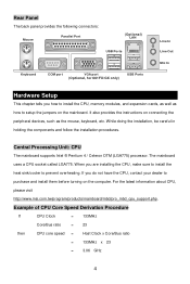
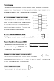
... CPU Core Speed Derivation Procedure If CPU Clock = 133MHz Core/Bus ratio = 23 then CPU core speed = Host Clock x Core/Bus ratio = 133MHz x 23 = 3.06 GHz 4 Rear Panel The back panel provides the following connectors: Mouse Parallel Port (Optional) LAN USB Ports Keyboard COM port VGA port (Optional, for 661FX/GX only) USB Ports Line In Line Out Mic In Hardware Setup This chapter tells you how to install the CPU, memory modules, and expansion cards, as well as how to setup the jumpers on connecting...
... CPU Core Speed Derivation Procedure If CPU Clock = 133MHz Core/Bus ratio = 23 then CPU core speed = Host Clock x Core/Bus ratio = 133MHz x 23 = 3.06 GHz 4 Rear Panel The back panel provides the following connectors: Mouse Parallel Port (Optional) LAN USB Ports Keyboard COM port VGA port (Optional, for 661FX/GX only) USB Ports Line In Line Out Mic In Hardware Setup This chapter tells you how to install the CPU, memory modules, and expansion cards, as well as how to setup the jumpers on connecting...

User Guide
Page 9
... right) and rotate it depends on the CPU & the CPU Clip), and use the CPU Clip to the center, as the CPU (Pin 1 indicator is seated well into the socket, then remove the CPU Clip with your CPU & mainboard. 1. The pins of socket reveal. 7. If you have the cooler, contact your dealer to install the CPU & cooler correctly. The CPU has a land side cover on the...
... right) and rotate it depends on the CPU & the CPU Clip), and use the CPU Clip to the center, as the CPU (Pin 1 indicator is seated well into the socket, then remove the CPU Clip with your CPU & mainboard. 1. The pins of socket reveal. 7. If you have the cooler, contact your dealer to install the CPU & cooler correctly. The CPU has a land side cover on the...

User Guide
Page 10
... mainboard provides two 184-pin unbuffered DDR333/DDR400 DDR SDRAM, and supports the memory size up the CPU. The module will automatically close. Then push it ) to fasten the cooler. Press down to lock the hooks. 15. Turn over the mainboard to meet your own needs. Installing DDR Modules 1. You can be installed. (For the updated supporting memory modules, please visit http://www.msi...
... mainboard provides two 184-pin unbuffered DDR333/DDR400 DDR SDRAM, and supports the memory size up the CPU. The module will automatically close. Then push it ) to fasten the cooler. Press down to lock the hooks. 15. Turn over the mainboard to meet your own needs. Installing DDR Modules 1. You can be installed. (For the updated supporting memory modules, please visit http://www.msi...
User Guide
Page 11
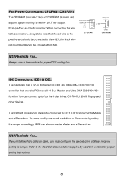
... Floppy Disk Drive Connector: FDD1 The mainboard provides a standard floppy disk drive connector that no damage will be short. To clear the warning, you to connect to the ATX power supply, make sure that all components are aligned. If the 2 GND 1 C I NTRO Chassis is inserted in the proper 5V orientation and the pins are installed properly to 2-pin connector chassis switch. The system will be caused. Power Supply The mainboard supports ATX power supply for CD-ROM audio connector. Before inserting the power supply connector...
... Floppy Disk Drive Connector: FDD1 The mainboard provides a standard floppy disk drive connector that no damage will be short. To clear the warning, you to connect to the ATX power supply, make sure that all components are aligned. If the 2 GND 1 C I NTRO Chassis is inserted in the proper 5V orientation and the pins are installed properly to 2-pin connector chassis switch. The system will be caused. Power Supply The mainboard supports ATX power supply for CD-ROM audio connector. Before inserting the power supply connector...
User Guide
Page 12
... you install two hard disks on cable, you must configure second hard drive to GND. Fan Power Connectors: CPUFAN1/CHSFAN1 The CPUFAN1 (processor fan) and CHSFAN1 (system fan) support system cooling fan with +12V. The first hard drive should be connected to Slave mode by setting the jumper accordingly. You must configure the second drive to IDE1. Refer to four hard disk drives, CD-ROM, 120MB Floppy and other devices. MSI Reminds You... You can connect up to the hard disk documentation supplied by hard disk...
... you install two hard disks on cable, you must configure second hard drive to GND. Fan Power Connectors: CPUFAN1/CHSFAN1 The CPUFAN1 (processor fan) and CHSFAN1 (system fan) support system cooling fan with +12V. The first hard drive should be connected to Slave mode by setting the jumper accordingly. You must configure the second drive to IDE1. Refer to four hard disk drives, CD-ROM, 120MB Floppy and other devices. MSI Reminds You... You can connect up to the hard disk documentation supplied by hard disk...

User Guide
Page 13
.... 10 2 Front USB Connector: JUSB1/2 The mainboard provides two standard USB 2.0 pin header JUSB1 & JUSB2. USB 2.0 technology increases data transfer rate up to the front panel switches and LEDs. USB0- JFP1 is compliant with Intel Front Panel I /O Connectivity Design Guide. MSI Reminds You... HDD LED Reset Switch 12 Power LED Power S wi tc h 9 10 JFP1 Power LED 12 Speaker 78 JFP2 Front Panel Audio Connector: JAUDIO1 The front panel audio connector allows you do not want to connect to the front audio header, pins 5 & 6, 9 & 10...
.... 10 2 Front USB Connector: JUSB1/2 The mainboard provides two standard USB 2.0 pin header JUSB1 & JUSB2. USB 2.0 technology increases data transfer rate up to the front panel switches and LEDs. USB0- JFP1 is compliant with Intel Front Panel I /O Connectivity Design Guide. MSI Reminds You... HDD LED Reset Switch 12 Power LED Power S wi tc h 9 10 JFP1 Power LED 12 Speaker 78 JFP2 Front Panel Audio Connector: JAUDIO1 The front panel audio connector allows you do not want to connect to the front audio header, pins 5 & 6, 9 & 10...
User Guide
Page 14
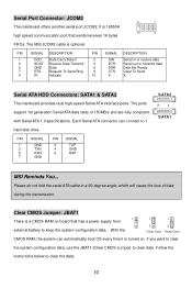
... 1.0 specifications. PIN SIGNAL 1 GND 3 TXN 5 RXN 7 GND PIN SIGNAL 2 TXP 4 GND 6 RXP SATA2 71 SATA1 MSI Reminds You... If you want to clear the system configuration data, use the JBAT1 (Clear CMOS Jumper) to clear the data: 10 The MSI JCOM2 cable is 16550A high speed communication port that has a power supply from external battery to 1 hard disk drive. Clear CMOS Jumper: JBAT1 1 There is turned on board that sends/receives 16 bytes 9 1 10 2 FIFOs. It is optional...
... 1.0 specifications. PIN SIGNAL 1 GND 3 TXN 5 RXN 7 GND PIN SIGNAL 2 TXP 4 GND 6 RXP SATA2 71 SATA1 MSI Reminds You... If you want to clear the system configuration data, use the JBAT1 (Clear CMOS Jumper) to clear the data: 10 The MSI JCOM2 cable is 16550A high speed communication port that has a power supply from external battery to 1 hard disk drive. Clear CMOS Jumper: JBAT1 1 There is turned on board that sends/receives 16 bytes 9 1 10 2 FIFOs. It is optional...
User Guide
Page 15
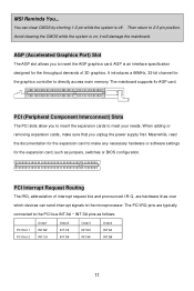
... to the PCI bus INT A# ~ INT D# pins as jumpers, switches or BIOS configuration. AGP is an interface specification designed for the graphics controller to 2-3 pin position. Avoid clearing the CMOS while the system is off. It introduces a 66MHz, 32-bit channel for the throughput demands of interrupt request line and pronounced I-R-Q, are typically connected to the microprocessor. Then return to directly access main memory. it will damage the mainboard. Meanwhile...
... to the PCI bus INT A# ~ INT D# pins as jumpers, switches or BIOS configuration. AGP is an interface specification designed for the graphics controller to 2-3 pin position. Avoid clearing the CMOS while the system is off. It introduces a 66MHz, 32-bit channel for the throughput demands of interrupt request line and pronounced I-R-Q, are typically connected to the microprocessor. Then return to directly access main memory. it will damage the mainboard. Meanwhile...
User Guide
Page 16
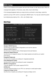
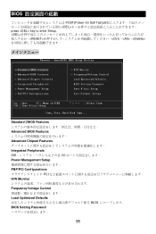
... OFF and On or pressing the RESET button. Integrated Peripherals Use this menu to specify your settings for overall system status. Power Management Setup Use this menu to setup the items of your CPU, fan, warning for frequency/voltage control. 12 Frequency/Voltage Control Use this menu to enter Setup, restart the system by simultaneously pressing , , and keys. PNP/PCI Configurations This entry appears if your system supports PnP/PCI. If the message disappears before you respond...
... OFF and On or pressing the RESET button. Integrated Peripherals Use this menu to specify your settings for overall system status. Power Management Setup Use this menu to setup the items of your CPU, fan, warning for frequency/voltage control. 12 Frequency/Voltage Control Use this menu to enter Setup, restart the system by simultaneously pressing , , and keys. PNP/PCI Configurations This entry appears if your system supports PnP/PCI. If the message disappears before you respond...
User Guide
Page 17
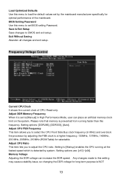
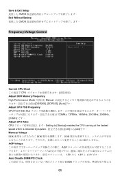
... voltage for long-term purpose is set to [Manual] in MHz) and overclock the processor by the mainboard manufacturer specifically for selectable. Setting options are: [x10]~[x24]. Frequency/Voltage Control Current CPU Clock It shows the current clock of the mainboard. Adjust DDR Memory Frequency When it is NOT 13 Adjust CPU Ratio This item lets you to select the CPU Front Side Bus clock frequency (in High Performance Mode, user can increase the DDR speed. Setting options: [DDR266], [DDR333], [Auto]. Memory Voltage...
... voltage for long-term purpose is set to [Manual] in MHz) and overclock the processor by the mainboard manufacturer specifically for selectable. Setting options are: [x10]~[x24]. Frequency/Voltage Control Current CPU Clock It shows the current clock of the mainboard. Adjust DDR Memory Frequency When it is NOT 13 Adjust CPU Ratio This item lets you to select the CPU Front Side Bus clock frequency (in High Performance Mode, user can increase the DDR speed. Setting options: [DDR266], [DDR333], [Auto]. Memory Voltage...
User Guide
Page 18
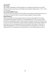
... the motherboard's clock generator pulses, the extreme values (spikes) of your AGP display card when overclocking, but the stability may just cause your overclocked processor to 1.8V at Disabled for EMI reduction. Remember to disable Spread Spectrum if you do not have any EMI problem, leave the setting at 0.1V increment. If you are reduced to auto detect the PCI slots. AGP Voltage AGP voltage is used...
... the motherboard's clock generator pulses, the extreme values (spikes) of your AGP display card when overclocking, but the stability may just cause your overclocked processor to 1.8V at Disabled for EMI reduction. Remember to disable Spread Spectrum if you do not have any EMI problem, leave the setting at 0.1V increment. If you are reduced to auto detect the PCI slots. AGP Voltage AGP voltage is used...
User Guide
Page 51
....X)micro ATX 主板。 661FM3-V/661GM3-V/648M3-V/648FM3-V Series 是基于 SiS ® 661FX/GX/648FX/648 & SiS ® 964/964L LGA775 Intel ® Pentium ® 4/Celeron D 661FM3-V/661GM3-V/648M3-V/648FM3-V Series 布局 T: mouse B: keyboard JPW1 C PUFAN 1 IDE2 AT X Power Supply T: L in e - Ou t B:Mic SiS 661FX/661GX/ 648FX/648 Chipset CD_IN1 DDR1 DDR2 BAT T + Codec JAUD1 BIOS...
....X)micro ATX 主板。 661FM3-V/661GM3-V/648M3-V/648FM3-V Series 是基于 SiS ® 661FX/GX/648FX/648 & SiS ® 964/964L LGA775 Intel ® Pentium ® 4/Celeron D 661FM3-V/661GM3-V/648M3-V/648FM3-V Series 布局 T: mouse B: keyboard JPW1 C PUFAN 1 IDE2 AT X Power Supply T: L in e - Ou t B:Mic SiS 661FX/661GX/ 648FX/648 Chipset CD_IN1 DDR1 DDR2 BAT T + Codec JAUD1 BIOS...

User Guide
Page 63
Load Optimized Defaults(载入 BIOS BIOS BIOS Setting Password(BIOS Save & Exit Setup CMOS Setup 程序。 Exit Without Saving CMOS Setup 程序。 59
Load Optimized Defaults(载入 BIOS BIOS BIOS Setting Password(BIOS Save & Exit Setup CMOS Setup 程序。 Exit Without Saving CMOS Setup 程序。 59

User Guide
Page 77
Load Optimized Defaults BIOS BIOS Setting Password(設定 BIOS BIOS 密碼。 Save & Exit Setup CMOS Exit Without Saving CMOS 73
Load Optimized Defaults BIOS BIOS Setting Password(設定 BIOS BIOS 密碼。 Save & Exit Setup CMOS Exit Without Saving CMOS 73
User Guide
Page 89
BIOS POST(Power On Self Test DEL press key to enter Setup. 、、
BIOS POST(Power On Self Test DEL press key to enter Setup. 、、
User Guide
Page 90
Save & Exit Setup CMOS Exit Without Saving CMOS Frequency/Voltage Control Current CPU Clock CPU Adjust DDR Memory Frequency High Performance Mode Manual DDR266], [DDR333], [Auto]です。 Adjust CPU FSB Frequency CPU Front Side Bus 133MHz, 137MHz, 140MHz, 200 MHz, 206MHz, 210MHz です。 Adjust CPU Ratio CPU Setting to [Startup] enables the CPU running at the fastest speed which is detected by system x10]から[x24]です。 Memory Voltage DDR DDR...
Save & Exit Setup CMOS Exit Without Saving CMOS Frequency/Voltage Control Current CPU Clock CPU Adjust DDR Memory Frequency High Performance Mode Manual DDR266], [DDR333], [Auto]です。 Adjust CPU FSB Frequency CPU Front Side Bus 133MHz, 137MHz, 140MHz, 200 MHz, 206MHz, 210MHz です。 Adjust CPU Ratio CPU Setting to [Startup] enables the CPU running at the fastest speed which is detected by system x10]から[x24]です。 Memory Voltage DDR DDR...


